Abstract
A novel dual-microphone speech enhancement technique is proposed in the present paper. The technique utilizes the coherence between the target and noise signals as a criterion for noise reduction and can be generally applied to arrays with closely-spaced microphones, where noise captured by the sensors is highly correlated. The proposed algorithm is simple to implement and requires no estimation of noise statistics. In addition, it offers the capability of coping with multiple interfering sources that might be located at different azimuths. The proposed algorithm was evaluated with normal hearing listeners using intelligibility listening tests and compared against a well-established beamforming algorithm. Results indicated large gains in speech intelligibility relative to the baseline (front microphone) algorithm in both single and multiple-noise source scenarios. The proposed algorithm was found to yield substantially higher intelligibility than that obtained by the beamforming algorithm, particularly when multiple noise sources or competing talker(s) were present. Objective quality evaluation of the proposed algorithm also indicated significant quality improvement over that obtained by the beamforming algorithm. The intelligibility and quality benefits observed with the proposed coherence-based algorithm make it a viable candidate for hearing aid and cochlear implant devices.
Keywords: Coherence function, coherent noise, microphone array, noise reduction
I. INTRODUCTION
ONE of the most common complaints made by hearing impaired listeners is reduced speech intelligibility in noisy environments. In realistic listening situations, speech is often contaminated by various types of background noise. Noise reduction algorithms for digital hearing aids have received growing interest in recent years. Although a lot of research has been performed in this area, a limited number of techniques have been used in commercial devices [1], [2]. One main reason for this limitation is that while many noise reduction techniques are performing well in the laboratory, they lose their effectiveness in everyday life listening conditions.
Generally, three types of noise fields are investigated in multi-microphones speech enhancement studies: (1) incoherent noise caused by the microphone circuitry, (2) coherent noise generated by a single well-defined directional noise source and characterized by high correlation between noise signals (3) diffuse noise, which is characterized by uncorrelated noise signals of equal power propagating in all directions simultaneously [3]. Performance of speech enhancement methods is strongly dependent on the characteristics of the environmental noise they are tested in. Hence, the performance of methods such as [4], [5] that work well in the diffuse field, starts to degrade when tested in coherent noise fields.
Traditionally, only one microphone is used in speech enhancement systems [6]. Recently, microphone array-based speech enhancement techniques have been widely accepted as a promising solution for noise suppression. Generally, by increasing the number of microphones in a speech enhancement system, placed in a noisy environment, further noise reduction is expected. But, the design of a microphone array for hearing aids faces serious difficulties in terms of size, weight and power consumption. Therefore, dual microphone speech enhancement systems can be considered as a trade-off. In the following, we present a brief overview of some of the dual-microphone speech enhancement techniques proposed in the literature.
Beamforming is one of the most well-known algorithms in this area. Fixed beamformers are designed to concentrate the array to the target sound source by combining the delayed and weighted versions of the input signal in each microphone. Two most common fixed beamformers presented in the literature are the delay-and-sum and superdirective beamformers [7]. Fixed beamformers utilize only information about the direction of the desired signal, however, adaptive beamformers also use the properties of captured signals by the array to further reject unwanted signals from other directions. An attractive realization of adaptive beamformers is the generalized sidelobe canceller (GSC) structure [8]. In [9]–[12] several variations of GSC have been investigated. The extension of GSC, suggested in [10] was called a two-stage adaptive beamformer. In studies carried out in [13], [14] an average speech reception threshold (SRT) (the signal-to-noise ratio at which 50% of the target speech is intelligible) improvement of 7-8 dB was achieved using this technique, with a single noise source at 90°, for both normal hearing listeners and cochlear implant (CI) patients. Although this extension of GSC outperforms the use of fixed directional microphones in scenarios with one simple jammer, in more complex scenarios its performance degrades significantly [2], [12]. Adaptive beamformers are very effective in suppressing coherent noise. The authors in [15] have shown that the noise reduction performance of GSC theoretically reaches infinity for coherent noises. In [16], an extension of beamforming with post-filtering, which gives beamformers the ability of suppressing noises that are uncorrelated has been investigated. Due to the small microphone spacing in hearing aids, noise signals captured by the microphones are highly correlated, and therefore GSC-based algorithms are preferred in these applications.
Over the past two decades, a few microphone array-based noise reduction algorithms have been applied to commercial CIs and hearing aids. In 1997, the Audallion BEAMformer™ was marketed by Cochlear Ltd. for the Nucleus 22-channel CI system. This beamformer uses two directional microphones, one at each ear, and based on the differences in amplitude and phase of the received signals, decides whether input signals come from front (desired range) or back (undesired range) hemisphere. This bilateral noise reduction system was tested in a mildly reverberant environment and showed an average SRT improvement of 2.5 dB over a fixed beamformer, but no improvement was reported in highly reverberant conditions [17]. In 2005, the beamformer suggested in [18] was implemented in the behind the ear (BTE) speech processor used in Cochlear's Nucleus Freedom CI system. This monaural adaptive beamformer is referred as BEAM™, and has been extensively evaluated in [2]. It has been shown in [2] that BEAM can yield substantial improvements in speech intelligibility for cochlear implant users, when a single interfering source is present. However, the presence of multiple noise sources reduces the overall performance of the BEAM considerably.
Another distinguished class of microphone array speech enhancement techniques are the coherence-based algorithms. The idea of using coherence function for speech enhancement was first proposed in [19]. The premise behind coherence-based techniques is that the speech signals in the two channels are correlated, while the noise signals are uncorrelated. Indeed, if the magnitude of the coherence function between the noisy signals at the two channels is one (or close to one), the speech signal is predominant and thus should be passed without attenuation, and if the magnitude is close to zero speech is absent, and thus the input signals should be suppressed. The main drawback of coherence-based methods is their weakness in suppressing coherent noise. In this case, noise signals at the two channels become highly correlated and will pass (with no attenuation) through the filter. In [20] the authors have suggested modifications to the coherence filter to address this issue. When dealing with correlated noise, this method estimates the cross-power spectral density (CSD) of noise signals in the two microphones and includes this parameter in the coherence filter. The fluctuations in the filter estimates introduce a high variance in the filter value, which in turn introduces musical noise in the output [21].
In this paper, we introduce a new coherence-based technique capable of dealing with coherent noise and applicable for hearing aids and cochlear implant devices. Similar to other studies in this area, we assume that the noise and target speech signals are spatially separated. The target speech signal originates from the front (0°), while noise source(s) can be placed at either the right or left hemispheres. In [22], we proposed a dual-microphone speech enhancement technique, which is based on the magnitude of coherence between input signals. The technique has the ability of suppressing coherent noise, emanating from a single interfering source. We tested the method with a single noise source at 90°, and obtained promising results in terms of speech intelligibility. This work generalizes that technique and is tested in more complex noise scenarios.
II. PROPOSED COHERENCE-BASED ALGORITHM
In this section, we start with a theoretical description of the coherence function and show how this function can be used as a criterion for noise reduction. Following that, the proposed coherence-based method is described in detail.
A. Definition of Coherence Function
The coherence takes values between zero and one and is an indicator of how well two signals correlate to each other at a particular frequency. Let us assume two microphones placed in a noisy environment in which the noise and target speech signals are spatially separated. In this case, the noisy speech signals, after delay compensation, can be defined as
| (1) |
where i denotes the microphone index, m is the the sample-index and xi(m) and ni(m) represent the (clean) speech and noise components in each microphone, respectively. After applying a short-time discrete Fourier transform (DFT) on both sides of (1), it can be expressed in the frequency domain as
| (2) |
where k is the frame index, ωl = 2πl/L and l = 0, 1, 2, ..., L − 1, where L is the frame length in samples. In the following equations we omit the subscript l for better clarity and call ω the angular frequency. In this paper, we consider the angular frequency in the range of [−π, π) rather than [0, 2π). The complex coherence function between the two input signals is defined as
| (3) |
where Φuv(ω, k) denotes the cross-power spectral density (CSD) defined as Φuv(ω, k) = E[U(ω, k)V*(ω, k)], and Φuu(ω, k) denotes power spectral density (PSD) defined as Φuu(ω, k) = E[|U(ω, k)|2]. The magnitude of the coherence function has been used in several studies as an objective metric to determine whether the target speech signal is present or absent at a specific frequency bin [19]–[21], [23]. The idea is that when the magnitude is close to one, the speech signal is present and dominant and when it is close to zero, the interfering signal is dominant. It should be noted that this assumption is typically valid for near-field sound sources in a diffuse noise field, where noise signals are not strongly correlated at the two channels. In general, decreasing the distance between two microphones increases the correlation of noise signals received by the microphones. In this case, even in a diffuse noise filed, noise signals become highly correlated especially at lower frequencies [24]. In a diffuse noise field, the coherence function is real-valued and can be analytically modeled by:
| (4) |
where sinc γ = (sin γ)/γ, fs is the sampling frequency, c ≃ 340 m/s the speed of sound and d the microphone spacing. Clearly, by decreasing inter-microphone distance, the correlation increases, i.e, Γu1u2 (ω) → 1.
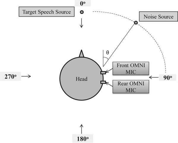
Before we start describing the proposed coherence-based method, we should point out that a coherent noise field is generated from a single well-defined directional sound source and in our case the omnidirectional microphones outputs are perfectly coherent except for a time delay. Fig. 1 depicts the configuration of two omnidirectional microphones with 20 mm inter-microphone distance on a dummy head. The target speech source is at 0° azimuth and a single noise source is placed at θ. Both sources are at a distance of 1.2 m from the microphones. In this case, the coherence function of the two input signals is obtained by [24]:
| (5) |
where θ is the angle of incidence. It should be pointed out that for our hearing aid application at hand, where the distance between the two microphones is fairly small (~ 20 mm), the aforementioned class of coherence-based algorithms [19]–[21], [23] are not suitable for suppressing coherent noise.
Fig. 1.
Placement of the two omnidirectional microphones and sound sources.
B. Proposed Method Based on Coherence Function
We first show that the coherence function between noisy signals in the two microphones can be computed from those of clean speech and noise signals. Assuming that the noise and speech components are uncorrelated, the CSD of the input signals, can be written as
| (6) |
After dividing both sides of the last equation by and omitting the ω and k indices for sake of clarity, we obtain:
| (7) |
Using the fact that the PSD of input signal in each channel is equal to sum of the PSDs of speech and noise signals on that channel, we can rewrite the last equation as follows:
| (8) |
Now let SNRi be the true local signal-to-noise ratio at the i-th channel, i.e.,
| (9) |
Substituting the above expression in (8), the following equation is obtained
| (10) |
Assuming the small microphone spacing in our application, we can suppose that the local SNR values at the two channels are nearly identical, such that SNR1 ≃ SNR2. Therefore, the last equation can be modified as follows
| (11) |
where SN̂R is a an approximation to both SNR1 and SNR2. Clearly, at higher SNR values the coherence of the noisy signals is affected primarily by the coherence of the speech signals, while at lower SNR values it is affected by the coherence of the noise signals. Based on the configuration shown in Fig. 1 and after applying (5) the last equation can be rewritten as follows:
| (12) |
where τ = fs (d/c). To verify the validity of the above equation, Fig. 2 shows a comparison between the coherence function of the noisy signals computed by (3) (true coherence), and the prediction (approximation) obtained using (12). For this comparison, we assume that we know the true SNR at the front microphone. Coherence values are shown in Fig. 2 for a sentence (produced by a male speaker) corrupted by speech-weighted noise. As it is evident from the figure, the predicted coherence values (magnitude and phase) follow the true coherence values quite well. To quantify the errors in the approximation of the magnitude of the coherence function, we used the reconstruction SNR measure [25], commonly employed in waveform coder applications to assess how close is the reconstructed waveform (following quantization) from the true input waveform. The reconstruction SNR measure, denoted as SNR∊, assesses the normalized distance between the true and predicted magnitudes of the coherence and is defined as follows:
| (13) |
Higher values of the SNR∊ measure indicate higher accuracy of the approximation (prediction). To quantify the errors in the prediction of the phase of true coherence, we used a phase distortion measure [26], defined, at frequency ω, as follows:
| (14) |
where is the phase operator and the expected value is taken over all frames. Small values of DM indicate better approximation. Table I shows results of the above measures averaged over 10 sentences. For this evaluation, speech-weighted noise was used at 75°. As can be seen, Eq. (12) provides a good estimate (prediction) of the true coherence values, at least for the low frequencies (f < 4 kHz).
Fig. 2.
Comparison between the true coherence of the noisy signals and its predicted values, based on (12), of the magnitude (left) and phase (right) at 1000 Hz. The noise source is located at 75° azimuth and SNR = 0 dB (speech-weighted noise).
TABLE I.
Quantification of the predictions of the magnitude and phase coherence function based on the measures defined in (13) and (14). Results are averaged for 10 sentences and mean and standard deviations of the measures are given (mean (SD)).
| Frequency | Input SNR | Magnitude Measure SNRε (dB) | Phase Measure DM (Radians) |
|---|---|---|---|
| 500Hz | 0 dB | 33.99 (2.84) | 0.01 (0.00) |
| 1kHz | 0 dB | 23.29 (1.55) | 0.04 (0.01) |
| 2kHz | 0 dB | 17.29 (1.47) | 0.07 (0.01) |
| 4kHz | 0 dB | 10.27 (1.19) | 0.35 (0.03) |
| 500Hz | 5 dB | 33.13 (1.98) | 0.01 (0.00) |
| 1kHz | 5 dB | 22.71 (1.84) | 0.04 (0.01) |
| 2kHz | 5 dB | 15.83 (1.10) | 0.07 (0.01) |
| 4kHz | 5 dB | 8.16 (1.02) | 0.42 (0.03) |
Next, we introduce the proposed suppression filter (gain function). We start by describing scenarios in which the noise source is located in the listener's right hemisphere (i.e. θ ≤ 180). The overall filter consists of two different filters, each designed to operate within a defined range of θ values. One filter is used for suppressing the interfering signals coming from the vicinity of 90°, and the other for dealing with situations, where 90° < θ ≤ 180°. It should be noted here that we do not make any assumptions about the position of the noise source being in the right hemisphere and we tackle the problem in its general form.
1) θ = 90°: Using (5), the coherence of the noise signals in this case is real-valued and equal to 1, since cos 90° = 0. Therefore, based on (12), the coherence function of the noisy signals has an imaginary part only when the speech signal is present. This fact suggests the use of a suppression function, which at low SNR levels (where the coherence of the noisy signals is affected primarily by the coherence of the noise - see (11)) attenuates frequency components whose real part of the coherence function is close to 1, while allowing for the remaining frequency components (dominated presumably by the target speech) to pass. It should be pointed that in low frequencies, even when speech is present, the imaginary part of the coherence function is very close to zero, since sin (ωτ) is very small. Based on this discussion, we propose the following filter for suppressing the noise signals emanating from around 90°
| (15) |
where is the real part operator and P(ω) is defined in two frequency bands as
| (16) |
where αlow and αhigh are two positive integer constants such that αlow > αhigh > 1. Assuming a sampling rate of 16 kHz, the threshold (π/8) in the last equation corresponds to 1 kHz, below which much of the energy in the speech spectrum is concentrated (see [27]). Within this range of frequencies, ω τ attains a value close to zero and therefore cos (ωτ) is close to one. Assuming high SNR in (12), we have . In this scenario, there exists the risk of speech attenuation in the lower frequencies since G1(ω, k) ≈ 0 , but by raising to the power of αlow in (15), the risk can be reduced. In fact, with the above setting of P(ω), the filter attenuates the lower frequency components, only when the real part of the coherence function is extremely close to one.
2) 90° < θ ≤ 180°: The following equation can easily be derived from (12):
| (17) |
where is the imaginary part operator. It is clear from the above equation that when SN̂R → 0 (−∞ dB), . When the noise source is located between 90° and 180°, sin (ω τ cos θ) is always negative. This conclusion is based on the assumptions that the angular frequency lies in the positive frequency range (ω < π), d is about or less than 20 mm, fs is at least 16 kHz, and therefore τ is a constant (less than 1). Hence, at frequency components where the noise is dominant, the likelihood that the imaginary part of the coherence function is less than zero increases. For example, let us assume θ = 180°. Letting in the last equation leads to SN̂R < 1 (0 dB), suggesting that the noise dominates the target signal. This example reveals that when the noise source is at 180° and the SNR is lower than 1, the imaginary part of the coherence function between the input signals is negative. When θ = 90°, in order to satisfy the condition , we require that SN̂R < 0 , which is not possible since both PSDs of speech and noise signals are always positive.
By designing a filter, which attenuates the frequency components having the imaginary part less than zero, we can suppress a significant amount of noise. However, zero is a strict threshold and we may obtain a very aggressive filter. Instead, non-zero thresholds are used in two frequency bands as follows
| (18) |
where βlow and βhigh are two negative constants such that βlow > βhigh > −1. Consequently, the filter is defined as
| (19) |
where μ is a small positive spectral flooring constant close to zero. By decreasing the value of μ we can increase the level of noise reduction at the expense of imposing extra speech distortion to the output. By setting μ = 0, we may introduce spurious peaks in the spectrum of the enhanced signals and subsequently musical noise in the output. For that reason, a small positive constant was chosen for μ. In (18), the threshold for lower frequencies is set closer to zero in comparison to the threshold for higher frequencies, since sin(ω τ cos θ) has a very small value at the lower frequencies. In this way, we prevent G2 from becoming aggressive in the lower frequencies.
3) Final Filter: Following the above discussion, the final filter proposed in this work is defined as follows:
| (20) |
From the definition of G2 in (19) and the discussion given earlier about the thresholds for SN̂R when 90° < θ ≤ 180°, it can be concluded that G2 takes value 1, when the noise is located at about 90°. Furthermore, when the noise source is not at 90°, the real part of the coherence function can not be very close to 1, since the coherence function of noise signals has an imaginary part. Therefore, in this condition G1 ≈ 1. We can thus say that the two filters G1 and G2 operate to some extent independent of one another, yet cover all possible angles. For instance, when the filter G1 is active (i.e., θ ≈ 90°), G2 ≈ 1 and therefore does not influence the overall (composite) suppression imparted by G(ω, k) in (20). Similarly, when the filter G2 is active (i.e., 90° < θ ≤ 180°), G1 ≈ 1 and therefore does not influence the overall suppression.
One major advantage of our algorithm is that, in contrast to many other methods proposed in the area of speech enhancement, it does not require estimation of the noise statistics to compute the gain function. In general, noise estimation is a challenging task particularly in adverse environments with low SNR and highly non-stationary noise sources. Inaccurate noise estimation can have a significant effect on the performance of speech enhancement algorithms. Noise underestimation leads to unnatural residual noise in the output, while noise overestimation can produce speech distortions [28]. As we will see in the next section, our proposed method performs well at low SNR with highly non-stationary background noise (e.g, multi-talker babble), since the filter does not rely on noise statistics or estimates.
In the above discussion, we assumed that the noise source is always on the right side of the listener. We can easily expand the theory to situations in which the source is on the left side. In this case, the filter G1 is used to suppress the noise signals coming from around 270°, since similar to signals coming from 90° the coherence of noise signals has no imaginary part (i.e., purely real). Furthermore, using the symmetric properties of cos, the explanation given for 90° < θ ≤ 180° can be applied to 180° < θ < 270° as well. Hence, G2 is also capable of suppressing interfering signals originating from this range of azimuth angles. So far, we have considered (and assumed) that only one noise source is present in the environment. However, we can easily generalize the above discussion to scenarios where more noise sources are present in different azimuths. In the next section, we show that the proposed method performs well in those situations as well.
C. Implementation
In this subsection, we provide the implementation details of the proposed coherence-based method. The signals picked up by the two microphones are first processed in 20 ms frames with a Hanning window and a 75% overlap between successive frames. After computing the short-time Fourier transform of the two signals, the PSDs and CSD are computed based on the following two first order recursive equations
| (21) |
| (22) |
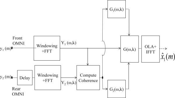
where (·)* denotes the complex conjugate operator and is a forgetting factor, set between 0 and 1. A more thorough discussion on optimal settings of this parameter can be found in [21]. These estimates of power spectral densities are used in (3), to compute the coherence function. We should mention that there exist other methods for computing the coherence function such as [29], [30]. The suppression function defined in (20) is applied to Y1(ω, k), corresponding to the Fourier transform of the input signal captured by the front microphone. To reconstruct the enhanced signal in the time-domain, we apply an inverse FFT and synthesize the signal using the overlap-add (OLA) method. Fig. 3 summarizes this procedure in a block diagram. The complete list of parameters used in this work is given in Table II. Although we have optimized the parameter values for our testing, we found that it is not necessary to change these values when changing the system configuration.
Fig. 3.
Block diagram of the proposed two-microphone speech enhancement technique.
TABLE II.
Parameter values used in the implementation of the coherence algorithm.
III. EXPERIMENTAL RESULTS
This section is devoted to the evaluation of the proposed technique. To assess the performance of the method, results of both listening tests and objective quality measurements are provided.
A. Test Materials and Subjects
Sentences taken from the IEEE database corpus [31] (designed for assessment of intelligibility) were used. These sentences (approximately 7-12 words) are phonetically balanced with relatively low word-context predictability. The root-mean-square amplitude of sentences in the database was equalized to the same root-mean-square value, which was approximately 65 dBA. The sentences were originally recorded at a sampling rate of 25 kHz and downsampled to 16 kHz. These recordings are available from [6]. Three types of noise (speech-weighted, multi-talker babble and factory) were used as maskers. The speech-weighted noise used, was adjusted to match the average long-term spectrum of the speech materials. The babble and factory noises were taken from the NOISEX database [32].
Ten normal hearing listeners, all native speakers of American English, participated in the listening tests. Their age ranged from 18 to 31 years (mean of 23 years). The listening tests were conducted in a double-walled sound-proof booth via Sennheiser HD 485 headphones at a comfortable level. All subjects were paid for their participation.
B. Methods and Noise Scenarios
The noisy stimuli captured at the two microphones were generated by convolving the target and noise sources with a set of HRTFs measured inside a mildly reverberant room ( T60 ≃ 220 ms) with dimensions 4.3 × 3.8 × 2.3 m3 (length × width × height). The HRTFs were measured using identical microphones to those used in modern hearing aids. The noisy sentence stimuli were processed using the following conditions: (1) the front omnidirectional microphone, (2) an adaptive beamformer algorithm and (3) the proposed coherence-based algorithm. The performance obtained with the use of the omnidirectional microphone alone will be used as a baseline to assess relative improvements in performance when no processing is taking place. In the following paragraph, we describe the adaptive beamformer algorithm used in this work.
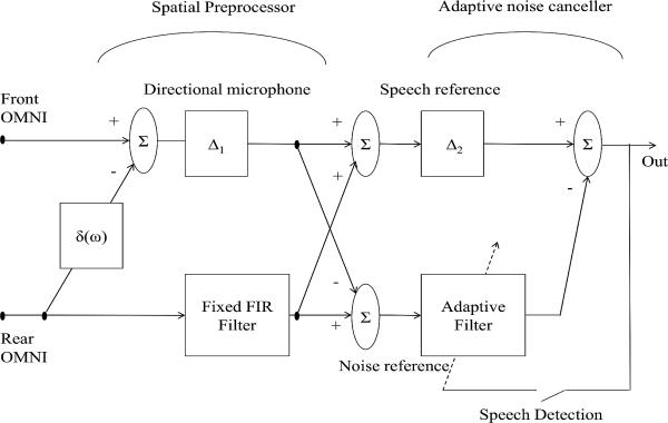
The two-stage adaptive beamformer is an extension of the GSC technique introduced in [10]. In that paper, a 5 dB improvement in SRT was reported between a hardware directional microphone and this beamformer. This technique includes two stages (spatial preprocessor and adaptive noise canceler), where each stage consists of an adaptive filter. The first filter was adapted only during speech-and-noise periods and was used to track the direction of the target signal. The second filter, similar to the adaptive filter used in conventional GSC, was updated with the normalized least-mean-square algorithm [33] to minimize the power of the output error. The authors in [11] modified the algorithm by replacing the first adaptive filter with a fixed FIR filter. In fact, this FIR filter offers a trade-off solution between the first adaptive filter in [9] and the fixed beamformer of the GSC [34]. The filter coefficients are determined and optimized for each hearing aid, assuming the target signal comes from 0° in an anechoic environment, in a way that the energy of the noise reference signal is minimized. Clearly, this is not a straightforward procedure, so we replaced the filter with a two-tap FIR filter, whose coefficients were optimized based on our experimental observations. Fig. 4 shows the block diagram of this technique. As it is apparent from the figure, before feeding the input signals into the first stage, a software directional microphone is created by using a fixed beamformer technique. The software microphone parameter is δ(ω) = a e−jωΔ0, and in this work we set a and Δ0 so as to give the microphone a cardioid directional pattern in anechoic conditions (null at 180°). Based on the configuration of the microphones, this can be done by providing one sample delay to the input signal of the rear microphone. A thorough discussion on creating a software directional microphone by two omnidirectional microphones can be found in [35]. In our implementation the adaptive filter has 64 taps, Δ1 and Δ2 are additional delays set to half of the size of the filters.
Fig. 4.
Block diagram of the two-microphone adaptive beamformer used for comparative purposes.
The test was carried out in seven different noise scenarios. In four of them, a single noise source generating speech-weighted noise was placed at either 75° ,90°, 120° or 180°. In the two noise scenarios, we consider two noise sources, one at 90°/180° and one at 75°/120°. The noise source at the lower azimuth angle generated speech-weighted noise and the other source generated multi-talker babble. The last scenario consists of three noise sources at 60°/90°/120°, with speech-weighted, babble and factory noises at the three sources respectively. The use of multi-talker babble as a point noise source is admittedly not realistic, but it has been used extensively in the speech enhancement literature focused on hearing-aid applications [2], [12]. Multi-talker babble is used in our study to assess the algorithm's performance in highly non-stationary environments.
C. Intelligibility Evaluation
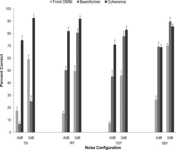
For the listening test, two IEEE lists (20 sentences) were used for each condition. In the single-noise source scenarios, algorithms were tested at two SNR levels (-5 dB and 0 dB). We did not test the methods at SNRs above 0 dB as we were constrained by ceiling effects (e.g., performance near 100% correct). However, informal listening tests showed that our method does not distort the speech signals at high SNR levels. Testing involved a total of 24 different listening conditions (3 algorithms × 2 SNR levels × 4 noise scenarios). The mean intelligibility scores of single noise scenarios, obtained as the percentage of total number of words identified correctly, are shown in Fig. 5. A substantial improvement in intelligibility was obtained with the proposed coherence-based algorithm relative to the baseline (front microphone) in all conditions. The beamformer implemented in this work has a null at 180°, and therefore shows expected performance improvement as the noise source gets closer to this azimuth angle. However, in other conditions the scores of coherence-based method are always higher than those of the beamformer.
Fig. 5.
Mean percent word recognition scores for ten normal-hearing listeners tested on IEEE sentences in single-noise source scenarios. Error bars indicate standard deviations.
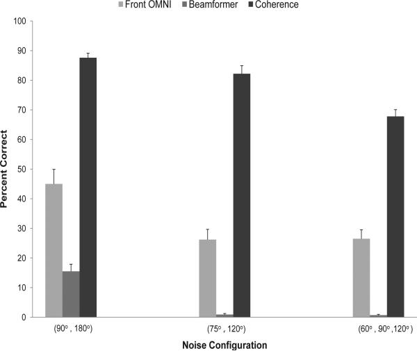
In the multiple-noise sources scenarios, algorithms were tested only at 0 dB. In total, 9 different listening conditions (3 algorithms × 1 SNR level × 3 noise scenarios) were tested. The mean intelligibility scores of these scenarios are shown in Fig. 6. As it is clear from the figure, the coherence-based technique performed favorably in these scenarios. In contrast, the results of the beamformer were inferior. This low performance is due to the fact that we have replaced the optimum fixed FIR filter proposed in [11] by a two-tap fixed filter that was manually optimized. However, the decrease in the scores of this beamformer technique in multiple-noise sources scenarios relative to those of single-noise scenarios is not surprising and has been reported in [2], [12], [36], [37] as well. In [37], a 2.5 dB and 5 dB decrease in speech-intelligibility weighted SNR (as defined in [38]) was reported after processing with an adaptive beamformer when multiple noise sources were present, and T60 was equal to 210 ms and 610 ms, respectively.
Fig. 6.
Mean percent word recognition scores for ten normal-hearing listeners tested on IEEE sentences in multiple-noise sources scenarios (SNR = 0 dB). Error bars indicate standard deviations.
In this study, we tested our method inside a mildly reverberant environment (T60 = 220 ms). Generally, in more reverberant conditions, the noise signals captured by the sensors will be less correlated. In such scenarios, the environmental noise can be modeled by a diffuse noise field rather than a coherent noise field. Considering a small microphone spacing, we can still assume that the noise signals captured by the two microphones are highly correlated for a wide range of frequencies. The impact of microphone spacing on the coherence function of noisy signals in a diffuse noise filed was reported in [24]. In reverberant conditions, our method will lose its ability to suppress the noise components that are not highly correlated. This problem can be resolved, however, by passing the output of our algorithm through a post-filter, such as a Wiener filter, and this warrants further investigation. Post-filtering techniques have been investigated in [16] for dealing with uncorrelated noise components that can not be easily suppressed by beamformers. A thorough review of post-filtering techniques that can be used with beamformers can be found in [39].
Another limitation of the proposed method, along with other methods, is that for θ < 90° the performance, in terms of noise suppression and intelligibility, starts to degrade as the masker gets closer to the target source. This is to be expected, since the proposed filer has no effect on the noise signals coming from an angle close to zero. In our experiments, we found that the method offers no benefit over the baseline condition (no processing) for θ < 45°. This limitation is also present in beamformers. In [11], for example, the improvement with the beamformer over that obtained with the front omindirectional microphone was less than 1 dB when the noise source was located at an angle less than 45°.
D. Speech Quality Evaluation
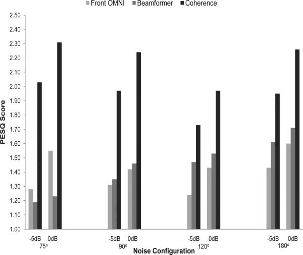
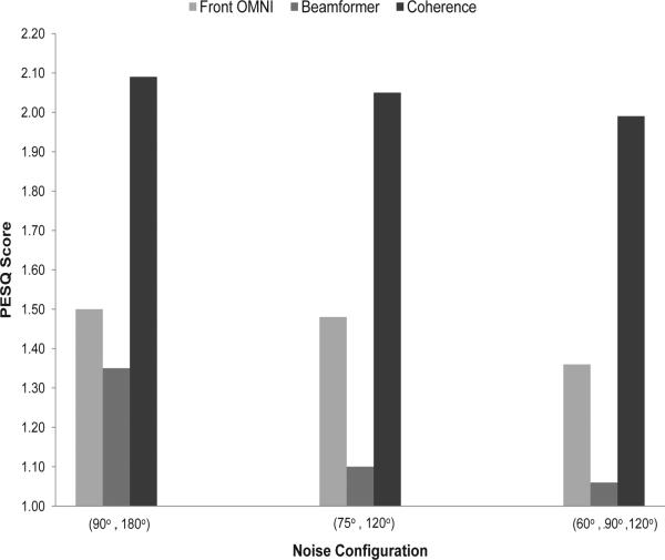
In this subsection we assess the performance of the various methods in terms of quality. This evaluation is done using an objective quality measure, and in particular, the Perceptual Evaluation of Speech Quality (PESQ) measure [40]. PESQ scores model mean opinion scores (MOS) and range from -0.5 (bad) to 4.5 (excellent). A high correlation between the results of subjective listening tests and PESQ scores was reported in [41] [42]. Figures 7 and 8 show the PESQ scores for the single and multiple interference scenarios, respectively. Clearly, the coherence-based method outperforms the beamformer in all noise configurations. The proposed method yielded an average improvement of 0.7 relative to the scores obtained using the front-microphone signals.
Fig. 7.
PESQ scores obtained in single-noise source scenarios.
Fig. 8.
PESQ scores obtained in multiple-noise sources scenarios (SNR = 0 dB).
As mentioned earlier, our technique does not require estimation of the noise statistics to compute the gain function. This gives the proposed method the advantage in coping with highly non-stationary noise including competing talkers. Further tests indicated that our algorithm was performing well even in competing-talker situations. In these tests, sentences produced by a different speaker (female speaker) were used as maskers. Table III shows the PESQ scores obtained by the proposed method and the beamformer in six different test conditions involving competing talkers. As can be seen, the proposed method outperformed the beamformer in all conditions. Performance obtained in the baseline OMNI condition was comparable, and in some cases, slightly better, than performance obtained with the beamformer. The reason the beamformer did not provide any benefit over the baseline (OMNI) condition is because it relies on VAD decisions. When speech is detected, adaptation is turned off (frozen) to prevent from suppressing the target speech signal. Hence, when the VAD detects speech presence (including that of the competing talker's), no suppression is applied to the input signals.
TABLE III.
PESQ scores obtained by the various methods in competing-talker conditions.
| Angle | SNR | OMNI | Beamformer | Coherence |
|---|---|---|---|---|
| 90° | -5 dB | 1.23 | 1.19 | 2.34 |
| 180° | -5 dB | 1.47 | 1.49 | 2.25 |
| (90°, 180°) | -5 dB | 1.17 | 1.20 | 1.82 |
| 90° | 0 dB | 1.62 | 1.31 | 2.62 |
| 180° | 0 dB | 1.84 | 1.60 | 2.54 |
| (90°, 180°) | 0 dB | 1.43 | 1.38 | 2.15 |
E. Spectrograms
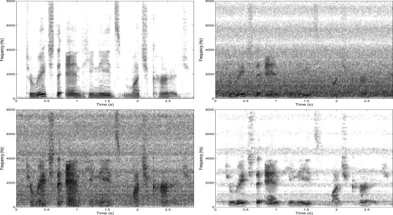
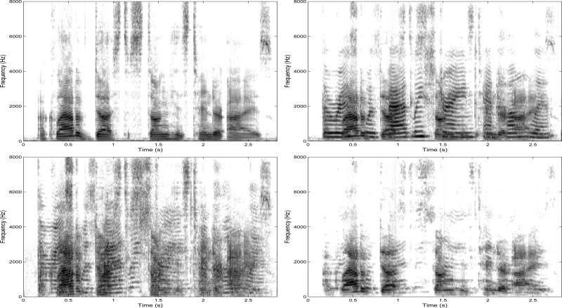
Speech spectrograms are a useful tool for observing the structure of the residual noise and speech distortion in the outputs of speech enhancement algorithms. Example spectrograms of clean and noisy speech and also those of the outputs of the beamformer and coherence-based methods are presented in Fig. 9 and Fig. 10 for speech embedded in speech-weighted noise and competing-talkers respectively. The figures shows that the background noise is suppressed to a greater degree with the proposed method than with the beamformer. This was done without introducing much distortion in the speech signal. The superiority of the proposed method over the beamformer is more apparent by comparing the spectrograms at low frequencies, where our method manages to recover the target speech signal components more accurately. These evaluations suggest that speech enhanced with our method will be more pleasant to human listeners than speech processed by the beamformer. This outcome is in agreement with the improvement in speech quality shown in Figures 7 and 8 and Table III.
Fig. 9.
Spectrograms of the clean speech signal (top left) and noisy signal (top right) captured by the front OMNI microphone. Speech is degraded by speech-weighted noise (SNR=0 dB) located at 90° azimuth. Bottom left panel shows enhanced signal by the beamformer and bottom right panel shows enhanced signal by the proposed coherence-based algorithm. The IEEE sentence was “To reach the end he needs much courage” uttered by a male speaker.
Fig. 10.
Spectrograms of the clean speech signal (top left) and noisy signal (top right) captured by the front OMNI microphone. Speech is degraded by interfering speech (SNR=0 dB) located at 120° azimuth. Bottom left panel shows enhanced signal by the beamformer and bottom right panel shows enhanced signal by the proposed coherence-based algorithm. The IEEE sentence was “A cloud of dust stung his tender eyes” uttered by a male speaker.
IV. CONCLUSIONS
The proposed dual-microphone algorithm utilizes the coherence function between the input signals and yields a filter, whose coefficients are computed based on the real and imaginary parts of the coherence function. The proposed algorithm makes no assumptions about the placement of the noise sources and addresses the problem in its general form. The suggested technique was tested in a dual microphone application (e.g., hearing aids) wherein a small microphone spacing exists. Intelligibility listening tests were carried out using normal-hearing listeners, who were presented with speech processed by the proposed algorithm and speech processed by a conventional beamforming algorithm. Results indicated large gains in speech intelligibly and speech quality in both single and multiple-noise source scenarios relative to the baseline (front microphone) condition in all target-noise configurations. The proposed algorithm was also found to yield substantially higher intelligibility and quality than that obtained by the beamformer, particularly in multiple noise-source scenarios and competing talkers. The simplicity of the implementation and intelligibility benefits make this method a potential candidate for future use in commercial hearing aids and cochlear implant devices.
ACKNOWLEDGMENT
The authors would like to thank Adam Hersbach (Cochlear Ltd., Melbourne, Australia) for providing access to the HRTFs used in the present study.
This work was supported by Grant No. R01 DC 010494 from the National Institute on Deafness and Other Communication Disorders (NIDCD) of the National Institutes of Health (NIH).
Biography
 Nima Yousefian received the B.S. degree in computer engineering from the University of Tehran, Iran in 2006, the M.S degree in computer engineering from Iran University of Science and Technology in 2009. Since 2009, he has been a Research Assistant at the University of Texas at Dallas (UTD), Richardson, TX, where he is pursuing the Ph.D. degree in electrical engineering.
Before joining UTD, he has worked as a Technical Engineer and a Software Developer in the automation industries. Now, he is working on the development of microphone array noise-reduction algorithms that can improve speech intelligibility. His general research interests include speech enhancement, speech recognition, and microphone array signal processing.
 Philipos C. Loizou (S'90-M'91-SM'04) received the B.S., M.S., and Ph.D. degrees in electrical engineering from Arizona State University, Tempe, in 1989, 1991, and 1995, respectively. From 1995 to 1996, he was a Postdoctoral Fellow in the Department of Speech and Hearing Science, Arizona State University, working on research related to cochlear implants. He was an Assistant Professor at the University of Arkansas, Little Rock, from 1996 to 1999. He is now a Professor and holder of the Cecil and Ida Green Chair in the Department of Electrical Engineering, University of Texas at Dallas. His research interests are in the areas of signal processing, speech processing, and cochlear implants. He is the author of the textbook Speech Enhancement: Theory and Practice (CRC Press, 2007) and co-author of the textbooks An Interactive Approach to Signals and Systems Laboratory (National Instruments, 2008) and Advances in Modern Blind Signal Separation Algorithms: Theory and Applications (Morgan & Claypool Publishers, 2010).
Dr. Loizou is a Fellow of the Acoustical Society of America. He is currently an Associate Editor of the IEEE Transactions on Biomedical Engineering and International Journal of Audiology. He was an Associate Editor of the IEEE Transactions on Speech and Audio Processing (1999-2002), IEEE Signal Processing Letters (2006-2009), and a member of the Speech Technical Committee (2008-2010) of the IEEE Signal Processing Society.
References
- 1.Hu Y, Loizou PC. A new sound coding strategy for suppressing noise in cochlear implants. J. Acoust Soc. Amer. 2008 Jul.124(1):498–509. doi: 10.1121/1.2924131. [DOI] [PMC free article] [PubMed] [Google Scholar]
- 2.Spriet A, Van Deun L, Eftaxiadis K, Laneau J, Moonen M, van Dijk B, Van Wieringen A, Wouters J. Speech understanding in background noise with the two-microphone adaptive beamformer BEAM in the nucleus freedom cochlear implant system. Ear Hear. 2007 Feb.28(1):62–72. doi: 10.1097/01.aud.0000252470.54246.54. [DOI] [PubMed] [Google Scholar]
- 3.Chen J, Phua K, Shue L, Sun H. Performance evaluation of adaptive dual microphone systems. Speech Commun. 2009 Dec.51(12):1180–1193. [Google Scholar]
- 4.McCowan IA, Bourlard H. Microphone array post-filter based on noise field coherence. IEEE Trans. Speech Audio Process. 2003 Nov.11(6):709–716. [Google Scholar]
- 5.Yousefian N, Rahmani M, Akbari A. Power level difference as a criterion for speech enhancement. Proc. Int. Conf. Acoust. Speech Signal (ICASSP’09); Taipei, Taiwan. Apr. 2009.pp. 4653–4656. [Google Scholar]
- 6.Loizou PC. Speech Enhancement: Theory and Practice. 1st ed. CRC Press, Taylor and Francis; 2007. [Google Scholar]
- 7.Bitzer J, Simmer K, Kammeyer K. Multimicrophone noise reduction techniques for hands-free speech recognition — a comparative study. Proc. Robust Methods for Speech Recognition in Adverse Conditions (ROBUST’99); Tampere, Finland. May 1999.pp. 171–174. [Google Scholar]
- 8.Griffiths L, Jim CW. An alternative approach to linearly constrained adaptive beamforming. IEEE Trans. Antennas Propag. 1982 Jan.130(1):27–34. [Google Scholar]
- 9.Van Compernolle D. Switching adaptive filters for enhancing noisy and reverberant speech from microphone array recordings. Proc. Int. Conf. Acoust. Speech Signal (ICASSP’90); Albuquerque, Mexico. Apr. 1990.pp. 833–836. [Google Scholar]
- 10.Berghe J, Wouters J. An adaptive noise canceller for hearing aids using two nearby microphones. J. Acoust Soc. Amer. 1998 Jun.103:3621–3626. doi: 10.1121/1.423066. [DOI] [PubMed] [Google Scholar]
- 11.Maj J, Wouters J, Moonen M. A two-stage adaptive beamformer for noise reduction in hearing aids. Proc. IEEE International Workshop on Acoustic Echo and Noise Control (IWAENC’01); Darmstadt, Germany. Sep. 2001. [Google Scholar]
- 12.Maj J, Royackers L, Wouters J, Moonen M. Comparison of adaptive noise reduction algorithms in dual microphone hearing aids. Speech Commun. 2006;48(8):957–970. [Google Scholar]
- 13.Maj J, Wouters J, Moonen M. Noise reduction results of an adaptive filtering technique for dual-microphone behind-the-ear hearing aids. Ear Hear. 2004;25:215–229. doi: 10.1097/01.aud.0000130794.28068.96. [DOI] [PubMed] [Google Scholar]
- 14.Wouters J, Berghe J, Maj J. Adaptive noise suppression for a dual-microphone hearing aid. Internat. J. Audiol. 2002;41(7):401–407. doi: 10.3109/14992020209090417. [DOI] [PubMed] [Google Scholar]
- 15.Bitzer J, Simmer K, Kammeyer K. Theoretical noise reduction limits of the generalized sidelobe canceller (GSC) for speech enhancement. Proc. Int. Conf. Acoust. Speech Signal (ICASSP’99); Phoenix, Arizona. Mar. 1999.pp. 2965–2968. [Google Scholar]
- 16.Marro C, Mahieux Y, Simmer K. Analysis of noise reduction and dereverberation techniques based on microphone arrays with postfiltering. IEEE Trans. Speech Audio Process. 1998 May;6(3):240–259. [Google Scholar]
- 17.Hamacher V, Doering W, Mauer G, Fleischmann H, Hennecke J. Evaluation of noise reduction systems for cochlear implant users in different acoustic environment. Am. J. Otol. 1997 Nov.18(6):46–49. [PubMed] [Google Scholar]
- 18.Wouters J, Vanden Berghe J. Speech recognition in noise for cochlear implantees with a two-microphone monaural adaptive noise reduction system. Ear Hear. 2001 Oct.22(5):420–430. doi: 10.1097/00003446-200110000-00006. [DOI] [PubMed] [Google Scholar]
- 19.Allen JB, Berkley DA, Blauert J. Multi-microphone signal processing technique to remove room reverberation from speech signals. J. Acoust Soc. Amer. 1977 Oct.62(4):912–915. [Google Scholar]
- 20.Le Bouquin-Jeannés R, Azirani AA, Faucon G. Enhancement of speech degraded by coherent and incoherent noise using a cross-spectral estimator. IEEE Trans. Speech Audio Process. 1997 Sep.5(5):484–487. [Google Scholar]
- 21.Guérin A, Le Bouquin-Jeannés R, Faucon G. A two-sensor noise reduction system: applications for hands-free car kit. EURASIP JASP. 2003 Mar.2003:1125–1134. [Google Scholar]
- 22.Yousefian N, Kokkinakis K, Loizou PC. A coherence-based algorithm for noise reduction in dual-microphone applications. Proc. Eur. Signal Processing Conf. (EUSIPCO’10); Alborg, Denmark. Aug. 2010.pp. 1904–1908. [Google Scholar]
- 23.Le Bouquin-Jeannés R, Faucon G. Using the coherence function for noise reduction. Inst. Electr. Eng. Proc.-I Commun., Speech, Vision. 1992 Jun.139(3):276–280. [Google Scholar]
- 24.Brandstein M, Ward D. Microphone Arrays: Signal Processing Techniques and Applications. Springer Verlag; Berlin, Germany: 2001. [Google Scholar]
- 25.Deller J, Proakis J, Hansen J. Discrete-time processing of speech signals. Prentice Hall: 1993. [Google Scholar]
- 26.Wilsky AS. Fourier series and estimation on the circle with applications to synchronous communication-Part I: Analysis. IEEE Trans. Inf. Theory. 1974 Nov.20(5):577–583. [Google Scholar]
- 27.Byrne D, Dillon H, Tran K, et al. An international comparison of long-term average speech spectra. J. Acoust Soc. Amer. 1994 Oct.96(4):2108–2120. [Google Scholar]
- 28.Martin R. Noise power spectral density estimation based on optimal smoothing and minimum statistics. IEEE Trans. Speech Audio Process. 2001 Jul.9(5):504–512. [Google Scholar]
- 29.Carter GC, Knapp CH, Nuttall AH. Estimation of the magnitude-squared coherence function via overlapped fast Fourier transform processing. IEEE Trans. Audio Electroacoust. 1973 Aug.21(4):337–344. [Google Scholar]
- 30.Benesty J, Chen J, Huang Y. Estimation of the coherence function with the MVDR approach. Proc. Int. Conf. Acoust. Speech Signal (ICASSP’06); Toulouse, France. May 2006.pp. 500–503. [Google Scholar]
- 31.IEEE recommended practice for speech quality measurements. IEEE Trans. Audio Electroacoust. 1969 Sep.19(3):225–246. [Google Scholar]
- 32.Varga A, Steeneken H. Assessment for automatic speech recognition: II. NOISEX-92: A database and an experiment to study the effect of additive noise on speech recognition systems. speech Commun. 1993 Jul.12(3):247–251. [Google Scholar]
- 33.Haykin S. Adaptive Filter Theory. Prentice Hall; New Jersey: 1996. [Google Scholar]
- 34.Maj JB. Ph.D. dissertation. Katholieke Universiteit Leuven; 2004. Adaptive noise reduction algorithms for speech intelligibility improvement in dual microphone hearing aids. [Google Scholar]
- 35.Kates J. Digital hearing aids. Plural Publishing; San Diego, California: 2008. [Google Scholar]
- 36.Kokkinakis K, Loizou PC. Multi-microphone adaptive noise reduction strategies for coordinated stimulation in bilateral cochlear implant devices. J. Acoust Soc. Amer. 2010 May;127(5):3136–3144. doi: 10.1121/1.3372727. [DOI] [PMC free article] [PubMed] [Google Scholar]
- 37.Van den Bogaert T, Doclo S, Wouters J, Moonen M. Speech enhancement with multichannel Wiener filter techniques in multimicrophone binaural hearing aids. J. Acoust Soc. Amer. 2009 Jan.125(1):360–371. doi: 10.1121/1.3023069. [DOI] [PubMed] [Google Scholar]
- 38.Greenberg J, Peterson P, Zurek P. Intelligibility-weighted measures of speech-to-interference ratio and speech system performance. J. Acoust Soc. Amer. 1993 Nov.94(5):3009–3010. doi: 10.1121/1.407334. [DOI] [PubMed] [Google Scholar]
- 39.Cohen I. Analysis of two-channel generalized sidelobe canceller (GSC) with post-filtering. IEEE Trans. Speech Audio Process. 2003 Nov.11(6):684–699. [Google Scholar]
- 40.Perceptual evaluation of speech quality (PESQ): An objective method for end-to-end speech quality assessment of narrowband telephone networks and speech codecs. ITU-T Recommendation P.862. 2000 [Google Scholar]
- 41.Rix A, Beerends J, Hollier M, Hekstra A. Perceptual evaluation of speech quality (PESQ) — A new method for speech quality assessment of telephone networks and codecs. Proc. Int. Conf. Acoust. Speech Signal (ICASSP’01); Salt Lake City, Utah. May 2001.pp. 749–752. [Google Scholar]
- 42.Hu Y, Loizou PC. Evaluation of objective quality measures for speech enhancement. IEEE Trans. Speech Audio Process. 2008 Jul.16(1):229–238. [Google Scholar]


