Abstract
MoS2nanofiber bundles have been prepared by hydrothermal method using ammonium molybdate with sulfur source in acidic medium and maintained at 180 °C for several hours. The obtained black crystalline products are characterized by powder X-ray diffraction (PXRD), Fourier transform infrared spectrometer (FTIR), X-ray photoelectron spectroscopy (XPS), scanning electron microscopy (SEM) and transmission electron microscopy (TEM). The PXRD pattern of the sample can be readily indexed as hexagonal 2H-MoS2. FTIR spectrum of the MoS2shows the band at 480 cm−1corresponds to the γas(Mo-S). SEM/TEM images of the samples exhibit that the MoS2nanofiber exist in bundles of 120–300 nm in diameter and 20–25 μm in length. The effects of temperature, duration and other experimental parameters on the morphology of the products are investigated.
Keywords: Hydrothermal, Nanofiber bundles, MoS2, Citric acid
Introduction
Nowadays, one-dimensional nanostructural materials (nanorods, nanowires, nanobelts and nanotubes) have attracted heightened attention because of their potential applications in nanodevices and functional materials [1]. Continuous effort has been devoted to the investigation on the crystalline phases of the layered transition metal dichalcogenides, because of their unusual crystal structure and unique physical and chemical properties [2]. In analogy to graphite, nanoparticles of many inorganic compounds such as MoS2, WS2 are not stable against folding, and can adopt nanotubular and fullerene-like structures [3]. As transition metal sulfides, MoS2 has been the subject of significant research for applications including nonaqueous lithium batteries, catalytic hydride sulfurization of petroleum and wear resistance. For each of these applications, the important processes occur either at the surface or at the exposed edges of the MoS2 layers [1]. MoS2 is a layered semiconductor (band gap = 1.2 eV, indirect) that resists oxidation even in moist air at temperatures up to 85 °C [4]. This attribute makes MoS2 an attractive semiconductor material for nanoscience applications. Recent studies have suggested that reducing the size of the MoS2 crystals can improve their lubrication properties in bearings, O-rings or other heavy—wear applications [5].
Inorganic syntheses using organic surfactants are successfully applied for the preparation of various nanostructural materials [6,7]. The subsequent template elimination without destruction of the mesoporous texture remains a difficult step [8]. Various methods of preparation includes chemical vapor deposition, sol–gel processing, spray pyrolysis, co-precipitation, sonochemical synthesis, metathesis reactions, two step electrochemical synthesis etc are having been in practice [9-12]. Tenne and co-workers [13,14] first reported the production of fullerene-like MoS2 nanotubes via the gas phase reaction between MoO3−x and H2S in a reducing atmosphere at elevated temperature (800–1000 °C). Rao and co-workers obtained MoS2 nanotubes by simple heating MoS3 in a stream of hydrogen under high temperature [15]. Zelenski et al. [16] synthesized fibers and tubules of MoS2 by the thermal decomposition of ammonium thiomolybdate precursors at 450 °C. MoS2 nanotubes [17] were made by subliming 2H–MoS2 powder in presence of H2S at 1300 °C. Recently MoS2 nanorods [18] were synthesized using α-MoO3 nanorods with a mixture of H2S · H2 (15 vol% of H2S) for 4 h at several temperatures. However, almost all the methods to obtain MoS2 nanotubes and nanorods utilize high temperature gas-solid reaction under reducing gas atmosphere. Yumei et al. [1,19] synthesized MoS2 nanorods and nanospheres by hydrothermal method using ammonium molybdate with Na2S in presence of NH2OH · HCl as oxidizing agent. Hydrothermal synthesis is becoming popular for environmental reason, since water is used as reaction solvent than organics. This method has been widely used to prepare nanostructures due to its simplicity, high efficiency and low cost.
In this article, as a part of our recent efforts on the investigation of 1-D materials [20], we report a simple low temperature hydrothermal method for preparation of MoS2 nanofiber bundles with morphology control. We examined the effect of precursors (ammonium molybdate, sodium sulphide and citric acid) concentration, duration and the temperature on the morphology of the product. Finally, we discuss appropriate conditions for producing MoS2 nanobundles.
Experimental section
Synthesis
The hydrothermal process was carried out like our previous report [21,22] to prepare MoS2 nanofiber bundles. In a typical synthesis of MoS2 nanofibers, sodium sulfide and H2S gas were used as sulfur sources in order to investigate the source effect on the morphology of the product.
In the first trail 1.235 g ammonium heptamolybdate tetrahydrate ((NH4)6Mo7O24 · 4H2O) was put into 25 mL distilled water under continuous stirring. After 10 min, 0.5 g citric acid monohydrate (C6H8O7 · H2O) was added to the above solution. To this solution mixture, 0.312 g sodium sulfide crystals were added. The initial greenish black color was changed to red after 1h stirring on a magnetic stirrer. In the subsequent trail, 0.5 g ammonium heptamolybdate tetrahydrate was put into 25 mL distilled water under continuous stirring. H2S gas is passed in to the warmed acidified with dilute HCl solution for about 5–8 min.
The sealed 25 mL Teflon lined autoclaves containing above solution mixture were placed for hydrothermal treatment at 180 °C for several hours. The autoclaves were cooled and the resulted black solid was retrieved from the solution by centrifugation, washed with distilled water followed by ethanol to remove the ions possibly remaining in the end product, and finally dried in air.
Characterization
Powder X-ray diffraction data were recorded on Philips X’pert PRO X-ray diffractometer with graphite monochromatized Cu Kα radiation (( = 1.541 Å). The Fourier transform infrared spectrum of the samples was collected using Nicollet FTIR spectrometer. Scanning electron micrograph images were taken with JEOL (JSM—840 A) scanning electron microscope. X-ray photoelectron spectroscopy was carried out on an ESCA-3 Mark II X-ray photoelectron spectrometer, (VG Scientific, UK) using Al Kα radiation (1486.6 eV) as the exciting source. The morphology of the samples was observed using (H-800EM Japan Hitachi) transmission electron microscope (TEM) equipped with EDS (Kevex Sigma TM Quasar, USA) to measure the elements contained in the samples.
Results and discussion
Figure 1a, b shows the PXRD patterns of the samples prepared using sodium sulfide and H2 as sulfur sources in acidic medium at 180 °C for 48 and 24 h, respectively. It shows only a broad, weak envelope beginning at 2θ = 30° and continuing out above 60°, the two maxima approximately located at the 100 and 110 positions of bulk 2H–MoS2[23]. The PXRD patterns resemble that of the single-layer MoS2 prepared by exfoliation method [24]. All the diffractions can be readily indexed as hexagonal 2H–MoS2 [space group P63/mmc (194)] with lattice constants a = 3.16116 Å and c = 12.2985 Å, identical to the reported data in the JCPDS cards (37–1492). At 180 °C only poor crystals were produced. The absence of the 002diffraction at 2θ = 14.4° suggests that absence of stacking, thus the sample should be an aggregate of single sheets of MoS2[1,8,18,23,25].
Figure 1.
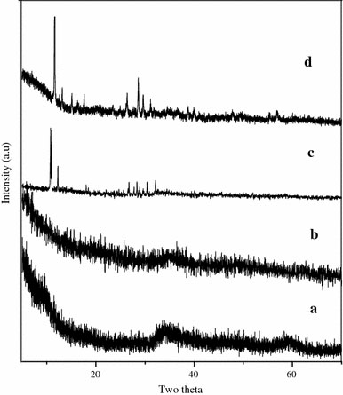
Powder XRD pattern of MoS2 nanofiber bundles prepared at (a) 180 °C for 48 h using Na2S as sulfur source with 0.5 g citric acid. (b) 180 °C for 24 h using H2S as sulfur source. (c) 180 °C for 48 h using Na2S as sulfur source without citric acid. (d) 180 °C for 48 h using Na2S as sulfur source with 1 g citric acid
Chemical analysis using EDS indicates the presence of Mo and S (elements of MoS2), and no other elements existed as observed in Fig. 2. Furthermore, the quantification of the peaks shows that the atomic ratio of S to Mo is 1.92, which is very close to the stoichiometric MoS2. From the IR spectrum (Fig. 3), it is observed that the band at 480 cm−1 corresponds to γas(Mo–S). The bands above 600 cm−1 correspond to Mo–O vibrations and they indicate that oxygen is present in similar types of coordination as in MoO3. We assign the band at 941 cm−1 to the γas(Mo–O) vibrations of terminal (–Mo=O) group and 693 cm−1 to γ(Mo–O) vibrations. The frequency of the vibration is shifted to the lower wavenumber compare to its standard value in crystalline MoO3, due to the presence of reduced Mo centers and sulfur as a ligand [26].
Figure 2.
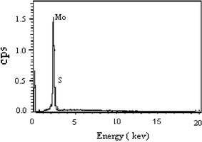
EDS pattern of MoS2 nanofiber bundles prepared at 180 °C for 48 h
Figure 3.
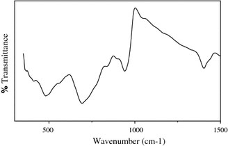
FTIR spectrum of MoS2 nanofiber bundles prepared at 180 °C for 48 h
X-ray photoelectron spectra of Mo(3d) and S(2p) core level regions of as-prepared nanoparticles are shown in Fig. 4a and b and the values are tabulated in Table 1. Mo(3d) peaks in as-prepared nanoparticles were deconvoluted into sets of spin-orbit doublet. Accordingly, the high intense Mo(3d5/2) peaks at 229.1 and low intense Mo(3d3/2) peak at 232.1 eV could be attributed to MoS2. Whereas lower binding energy shoulder peak at 226.25 eV is because of S(2s) [27].
Figure 4.
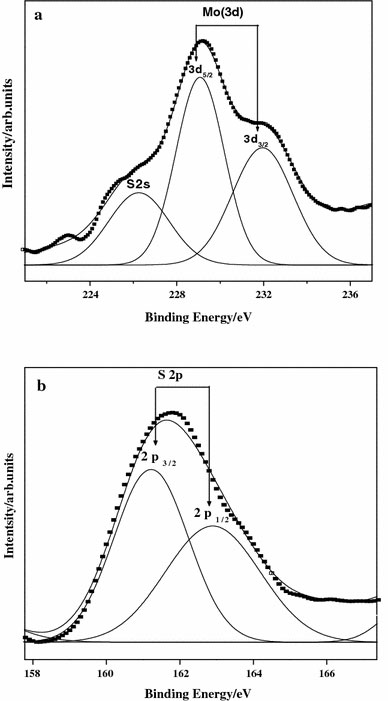
XPS pattern of MoS2 nanofiber bundles prepared at 180 °C for 48 h
Table 1.
XPS data of Mo(3d) and S(2p)
| Peak | Area | Binding energy (eV) | FWHM (eV) | Peak height (Intensity) |
|---|---|---|---|---|
| Mo3d3/2 |
481.32 |
232.1 |
2.7661 |
138.84 |
| Mo3d5/2 |
612.97 |
229.1 |
2.1874 |
223.59 |
| S2s |
295.81 |
226.25 |
2.7571 |
85.605 |
| S(2p3/2) |
113.89 |
161.25 |
2.0538 |
44.248 |
| S(2p1/2) | 110.89 | 162.94 | 2.8032 | 31.562 |
WHM = Full Width Half Maximum
Figure 4b shows S(2p) doublet peak (2p3/2 and 2p1/2) at 161.25 and 162.94 eV respectively in which 2p3/2 and 2p1/2 orbital peaks coincide with each other. It is to be noted that the peak positions of S(2p) and Mo(3d5/2) for MoS2 is in good agreement with he results on MoS2[28].
The chemical shifts of Mo(3d5/2) and S(2p) in MoS2 nanoparticle is +1.6 and −2.2 eV in comparison to elemental Mo and S [29]. The electronegativity of S being 2.5 is greater than that of Mo being 1.8. Therefore there occurs some partial electron transfer from molybdenum to sulfur. As a result, molybdenum becomes positively charged as shown by the increase in binding energy and sulfur becomes negatively charged as shown by the decrease in binding energy.
MoS2nanofiber of about 120–300 nm in diameter and 20–25 μm in length are identified from SEM images (Fig. 5). They are well aligned and occur in-group of bundles with very high aspect ratio. It can be seen that the nanofiber self assembled into bundles and the nanofiber in a bundles had the same growth direction. The morphology and structure of individual MoS2 nanorods have been characterized in further detail using TEM, which are shown in Fig. 6. It can be seen that the nanorods are straight and uniform along their entire length and thickness of about up to 300 nm. The ends of the nanorods are broken. Figure 6d is the high resolution TEM image of the MoS2 nanorods and this image shows solid nanorods are uniform in thickness.
Figure 5.
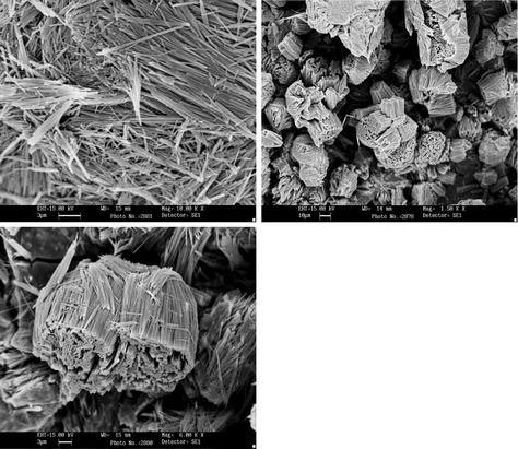
SEM images of MoS2 nanofiber bundles prepared at 180 °C for 48 h
Figure 6.
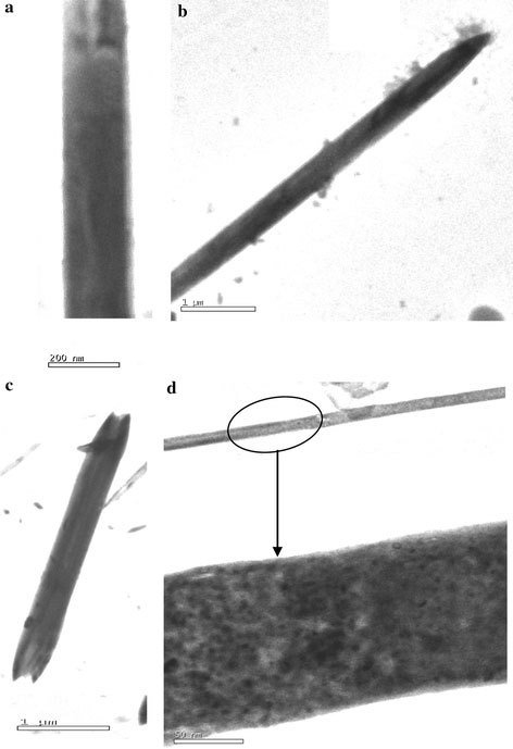
TEM images of MoS2 nanofiber bundles prepared at 180 °C for 48 h
The reduction of transition metal ions by surfactant is useful for the production of ultra fine particles of metal sulfides. Unfortunately, molybdic compound reduction chemistry is quite complex and the nature of the products strongly depends on the reaction conditions. For example, Afanasiev et al. show that the reduction of aqueous ammonium molybdate at different temperatures and conditions yields binary sulfides such as MoS5.6, MoS6, and MoS3 as well as binary oxides such as MoO3 and MoO2. In fact, the mechanism differs markedly in aqueous and in nonaqueous solutions. In order to disclose the transition process from (NH4)6Mo7O24 · 4H2O to MoS2, the role of citric acid [30-32] on phase of products was investigated. The possible reaction mechanism can be written as
 |
| (1) |
Step 1 is a sulfureted reaction, in which an intermediate phase (NH4)2MoS4 is produced [33], and step 2 is a reduction reaction under hydrothermal conditions. Thus by the addition of 1 g of citric acid or without citric acid, sulfureted reaction and reduction reaction do not react completely so that the products consist of much MoO3 phase as shown in the Fig. 1c, d. Therefore during the formation of MoS2 nanofiber bundles, citric acid plays a very prominent role. Figure 7a, b gives the SEM images of the product prepared with and without citric acid. We evaluate the effect of temperature and duration on the morphology of the products. But there was no interesting morphology of the product obtained.
Figure 7.
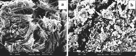
SEM images of MoS2 nanofiber bundles prepared at (a) 180 °C for 48 h with 1 g citric acid and (b) without citric acid
The morphology of the product prepared at 180 °C for 24 h (Fig. 8) using H2 resembles with the morphology of the product prepared at 180 °C for 48 h (Fig. 5) using sodium sulfide as sulfur source. Here, there is a regular arrangement of MoS2 fibers takes place to form bundles. The thickness of the fiber is found to be about 300 nm and length is about 12 μm. From the SEM images, we observed that the length of all fibers is found to be same with sharp ends having voids in each MoS2 bundles.
Figure 8.
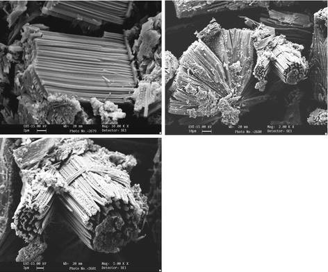
SEM images of MoS2 nanofiber bundles prepared at 180 °C for 24 h using H2S as sulfur source
The possible reaction mechanism can be written when H2S as sulfur source is
| (2) |
| (3) |
Step 3 is a reduction reaction, in which an intermediate phase MoCl4 is produced [19], and step 4 is a sulfureted reaction under hydrothermal conditions.
Figure 9a, b shows the SEM images of MoS2 prepared at 180 °C for 16 and 20 h. When the duration is increased to 48 h, nanorods (Fig. 9c) are obtained. The thickness of the nanorods is found to be in the range of 200–600 nm.
Figure 9.
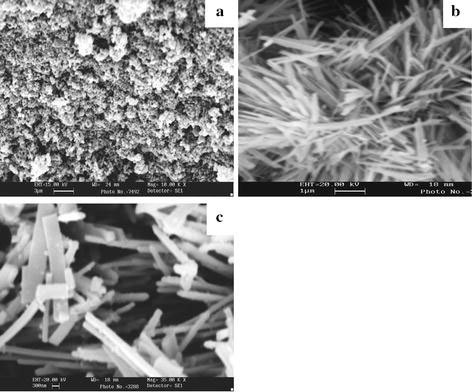
SEM images of MoS2 nanofiber bundles prepared at 180 °C h using H2S for (a) 16 h (b) 20 h and (c) 48 h
Conclusion
Nanofiber of MoS2bundles with 150–300 nm in diameters and 20–25 μm in length have been successfully synthesized by a simple low temperature hydrothermal method. PXRD pattern indicated the amorphous MoS2was made up of single layer and layer stacking had not taken place. The nanofiber self assembled into bundles and the nanofiber bundle had the same growth direction. SEM study reveals the formation of bundles of well-aligned MoS2nanofiber with very high aspect ratio. Since the MoS2nanomaterials are often very difficult to prepare and the search for more simple routine is quite valuable with regard to energy-saving and less pollution. It can be demonstrated that the optimum conditions for preparing MoS2nanofiber are at 180 °C for 48 h using citric acid and 180 °C for 24 h by passing H2S in presence of HCl. Under these conditions the morphology of the products resembles to one another.
Acknowledgments
The author G. T. Chandrappa thankful to the Department of Science and Technology, NSTI Phase-II, New Delhi, Government of India for financial support to carryout this research work. We also thank the Central Facility, Dept. of Physics and Dept. of Metallurgy, Indian Institute of Science, Bangalore for collecting XRD data and SEM images.
References
- Y. Tian, J. Zhao, W. Fu, Y. Liu, Y. Zhu, Z. Wang, Mater. Lett. 59, 3452 (2005)
- Wilson JA, Di Saluo FJ, Majaham S. Adv. 1972. p. 117. [DOI]
- C.N.R. Rao, Manish Nath. Dalton Tran. 1 (2003)
- Ross S, Sussman A. J. Phys. Chem. 1995. p. 889. [DOI]
- Stender CL, Greyson EC, Babayan Y, Odom TW. Adv. 2005. p. 2837. COI number [1:CAS:528:DC%2BD2MXhtlalu7rI] [DOI]
- Krumeich F, Muhr HJ, Neiderberger M, Bieri F, Schnder B, Nesper R. J. 1999. p. 8324. COI number [1:CAS:528:DyaK1MXlsFSktrk%3D] [DOI]
- Durupthy O, Jaber M, Steunou N, Maquet J, Chandrappa GT, Livage J. Chem. 2005. p. 6395. COI number [1:CAS:528:DC%2BD2MXht1SmtrrF] [DOI]
- Afanasiev P, Xia G-F, Berhault G, Jouguet B, Lacroix M. Chem. 1999. p. 3216. COI number [1:CAS:528:DyaK1MXmvVeqtLo%3D] [DOI]
- Close MR, Petersen JL, Kugler EL. Inorg. 1999. p. 1535. COI number [1:CAS:528:DyaK1MXhsFOms7c%3D] [DOI]
- Mdleleni MM, Hyeon T, Suslick KS. J. 1998. p. 6189. COI number [1:CAS:528:DyaK1cXjslehs7g%3D] [DOI]
- Bonneau PR, Jarvis RF, Kaner RB. Nature. 1991. p. 510. COI number [1:CAS:528:DyaK3MXhtVOlsLg%3D] [DOI]
- Li Q, Newberg JT, Walter EC, Hemminger JC, Penner RM. Nano Lett. 2004. p. 277. COI number [1:CAS:528:DC%2BD2cXjs1antw%3D%3D] [DOI]
- Tenne R, Margulus L, Genut M, Hodes G. Nature. 1992. p. 444. [DOI]
- Feldman Y, Frey GL, Homyonfer M, Lyakhovitskaya V, Margulis L, Cohen H, Hodes G, Hutchison JL, Tenne R. J. 1996. p. 5362. COI number [1:CAS:528:DyaK28XjtFWlsrg%3D] [DOI]
- Nath M, Govindaraju A, Rao CNR. Adv. 2001. p. 283. COI number [1:CAS:528:DC%2BD3MXitVCrsb8%3D] [DOI]
- Zelenski CM, Dorhout PK. J. 1998. p. 734. COI number [1:CAS:528:DyaK1cXms1OmtQ%3D%3D] [DOI]
- Hsu WK, Chang BH, Zhu YQ, Han WQ, Terrones HM, Grobert N, Cheetham AK, Kroto HW, Walton DRM. J. 2000. p. 10155. COI number [1:CAS:528:DC%2BD3cXmslGjtbk%3D] [DOI]
- Albiter MA, Huirache-Acuna R, Paraguay-Delgado F, Rico JL, Alonso-Nunez G. Nanotechnology. 2006. p. 3473. COI number [1:CAS:528:DC%2BD28XhtVaksL3N] [DOI] [PubMed]
- Tian Y, Zhao X, Shen L, Meng F, Tang L, Deng Y, Wang Z. Mater. 2006. p. 527. COI number [1:CAS:528:DC%2BD2MXht1OisL7N] [DOI]
- Nagappa B, Chandrappa GT, Livage Jacques. Pramana-J. 2005. p. 917. COI number [1:CAS:528:DC%2BD2MXhtleqsb7M] [DOI]
- Chandrappa GT, Steunou N, Cassaignon S, Bisvais C, Biswas PK, Livage J. J. 2003. p. 593. COI number [1:CAS:528:DC%2BD38XotFGisLw%3D] [DOI]
- Chandrappa GT, Livage J. Syn. 2006. p. 23. COI number [1:CAS:528:DC%2BD28XhsVKrurc%3D]
- Joensen P, Frindt RF, Morrison SR. Mater. 1986. p. 457. COI number [1:CAS:528:DyaL28XktFOjsLk%3D] [DOI]
- Peng Y, Meng Z, Zhong C, Lu J, Yu W, Yang Z, Qian Y. J. 2001. p. 170. COI number [1:CAS:528:DC%2BD3MXks1WktL4%3D] [DOI]
- Y. Tian, Y. He, Y. Zhu, Mater. Chem. Phys. 87, 87 (2004)
- Weber Th, Muijsers JC, Van Wolput JHMC, Verhagen CPJ, Niemantsverdriet JW. J. 1996. p. 14144. COI number [1:CAS:528:DyaK28XksV2lsLc%3D] [DOI]
- D. Briggs, M.P. Seah, Practical Surface Analysis by Auger and X-ray Photoelectron Spectroscopy (Wiley New York 1984), p. 503.
- Pouzet J, Hadouda H, Bernede JC, Le Ny R. Phys. Chem. Solids. 1996. p. 1363. COI number [1:CAS:528:DyaK28XltFGksL4%3D] [DOI]
- Wang W, Skeldon P, Thompson GE. Surf. 1997. p. 200. COI number [1:CAS:528:DyaK2sXktF2nsrY%3D] [DOI]
- Matzapetakis M, Raptopolou CP, Tsohos A, Papaefthymiou V, Moon N, Salifoglou A. J. 1998. p. 13266. COI number [1:CAS:528:DyaK1cXns1ymsbY%3D] [DOI]
- Tsay J-d, Fang T-t. J. 1999. p. 1409. COI number [1:CAS:528:DyaK1MXktVyrsro%3D] [DOI]
- Kakihana M, Nagumo T, Okamoto M, Kakihana H. J. 1987. p. 6128. COI number [1:CAS:528:DyaL2sXmt1OrtLc%3D] [DOI]
- Pan W, Leonowicz ME, Stiefel EI. Inorg. 1983. p. 612. [DOI]


