Abstract
Concentric tube robots are a novel continuum robot technology that is well suited to minimally invasive surgeries inside small body cavities such as the heart. These robots are constructed of concentrically combined pre-curved elastic tubes to form 3D curves. Each telescopic section of the robot is either of fixed or variable curvature. One advantage of this approach is that the component tube curvatures, lengths and stiffnesses can easily be fabricated to be procedure- and patient-specific. This paper proposes an optimization framework for solving the robot design problem. Given a 3D description of the constraining anatomy, the number of fixed and variable curvature robot sections and a tip workspace description, the algorithm solves for the robot design that possesses the desired workspace, remains inside the anatomical constraints and minimizes the curvature and length of all sections. The approach is illustrated in the context of beating-heart closure of atrial septal defects.
I. INTRODUCTION
CONCENTRIC tube robots possess cross sections comparable to needles and catheters, but are capable of substantial actively-controlled lateral motion and force application along their entire length. Since robot shape can be controlled, they enable navigation through the body along 3D curves. Furthermore, the lumen of the tubes can house additional tubes and wires for controlling articulated tip-mounted tools. An example is shown in Fig. 1.
Fig. 1.
Concentric tube robot comprised of four telescoping sections that can be rotated and translated with respect to each other.
In the last few years, substantial progress has been made in developing this technology [1]-[5]. Mechanics models have been derived for computing the kinematics [1],[2] and deformation due to external loading [3],[4]. Solution of the anatomically-constrained inverse kinematic problem has been considered in [6],[7]. Real-time implementations of position control [1] and stiffness control [5] have been demonstrated in the laboratory. Position control has also been employed in beating-heart intracardiac animal trials.
A topic that has received little attention is how to design concentric tube robots to meet the constraints imposed by a specific surgical task and anatomical environment. This is not surprising given the modeling complexity of these robots. In contrast to standard robots possessing rigid links and discrete joints, concentric tube robots are continuum robots. When their constituent pre-curved tubes are inserted inside each other, their common axis conforms to a mutual resultant curvature. By controlling relative translations and rotations of the tubes at their proximal ends, the shape and length of the robot can be varied. Thus, the tubes act as both links and flexure joints.
The resulting coupled kinematic and quasistatic force model is a 3D beam-bending problem that can be expressed as a two-point boundary value problem involving a differential equation with respect to arc length along the common centerline of the tubes [4]. The kinematic input variables (tube rotations and displacements at the proximal end) enter the problem as a subset of the boundary conditions. The remaining boundary conditions are comprised of point forces and torques applied to the distal ends of the tubes. Contact along the robot's length (e.g., with tissue) generates additional distributed and point loads.
Given this complexity, it is very difficult to predict the workspace and arm motions produced by a robot constructed from tubes of arbitrary pre-curvature and relative stiffness. A design methodology has been proposed in [1], however, that is based on achieving three desirable properties of a minimally invasive robotic instrument:
The ability to navigate narrow curved passages and, if penetrating tissue, exert minimal lateral forces,
The ability to manipulate distal links independent of proximal links, i.e., a decoupling of the robot's links, and
The ability to perform complex tissue manipulations at the surgical site using only the distal links.
The design methodology that provides these properties is encapsulated in four design rules.
(1) Telescoping dominant stiffness
The stiffnesses of the tubes are selected such that each telescoping section dominates all those sections extending from it. The result is that the shape and displacement of each telescoping section is kinematically decoupled from that of the proximal sections. This rule provides the second property.
(2) Fixed and Variable Curvature Sections
Each telescoping section is designed to have either fixed or variable curvature. A fixed curvature section relaxes to the shape of its pre-curvature when it is extended from the preceding section. In contrast, a variable curvature section can take on a continuous range of curvatures usually ranging between zero (straight) and a maximum value. A single tube is required to construct a constant curvature section while two tubes are needed to construct a variable curvature section. See [1] for a detailed description of how variable and constant curvature sections are constructed. This design rule is analogous to defining the types of joints (and thus link motions) of the robot.
(3) Piecewise Constant Initial Tube Curvatures
When using telescopic extension to navigate narrow curved passages or penetrate tissue, the only robot shape that does not produce lateral motion or forces is one of piecewise constant curvature. During telescopic extension, the order of extension must proceed from the proximal section to the distal one. It has been demonstrated that by pre-curving each tube such that its curvature is piecewise constant, the combined telescoping curvature is also approximately piecewise constant [1]. Design rules (2) and (3) provide the first property desired for minimally invasive instruments.
(4) Increasing Curvature from Base to Tip
Larger section curvatures produce greater displacements and rotations for a given section length. By employing larger curvatures for the distal sections, these sections can be designed to possess a significantly sized workspace at the robot tip without relying on motion of the proximal sections. This approach is in accord with the mechanics since the distal sections are comprised of the smaller-diameter inner tubes and thus experience less strain for a given curvature than the larger-diameter outer tubes [1]. This rule provides the third property.
In summary, tube diameters and initial curvatures are selected such that the robot behaves as a concatenation of kinematically-independent constant curvature and variable curvature sections. Each constant curvature section has two kinematic input variables,{l,θ} and contributes two degrees of freedom corresponding to the extension length and rotation of the section. Since variable curvature sections are constructed from two tubes, they possess three kinematic input variables {θ1,θ2,l} and contribute three degrees of freedom to the robot. The angles {θ1,θ2} control rotation and curvature of the section and l controls arc length (Fig. 1).
Using these design rules, the robot design problem is to select (i) the number of telescoping sections, (ii) the type of each section (fixed or variable curvature) and (iii) the curvature and maximum length of each section based on surgical-task workspace requirements and anatomical constraints.
The contribution of this paper is to solve for the section curvatures and lengths assuming that the number and type of sections is known. For fixed-curvature sections, the curvature value is a constant while for variable curvature sections, the maximum curvature value is determined. Given the desired curvatures, the robot can be easily fabricated [1].
This paper also introduces a novel decomposition of the design problem into a set of two optimization problems. The distal sections are first designed to achieve the desired surgical workspace and, subsequently, the proximal sections are designed to navigate and position the distal sections at the surgical site.
The paper is arranged as follows. Section II formalizes the design problems to be solved. In Section III, the design problems are posed as optimization problems and a numerical approach to their solution is proposed. Section IV applies the proposed approach to the design of a robot for intracardiac surgery. Conclusions are presented in Section V.
II. ROBOT DESIGN
Minimally invasive medical procedures involve the manipulation of tools, sensors and prosthetic devices inside the body while minimizing damage to surrounding tissue structures. In many cases, navigation to the surgical site involves steering the instrument along three-dimensional curves through body cavities (e.g., the vasculature). Once at the surgical site (e.g., the heart), it is often necessary to control the position and orientation of the instrument's distal tip to manipulate tools while holding relatively immobile the proximal inserted length.
This leads to a natural decomposition over the length of the robot into a proximal portion responsible for navigation and a distal portion for manipulation. Many surgeries in addition to cardiac surgery fit this decomposition. These include surgeries in the ventricles of the brain, the throat, the lungs and the kidneys.
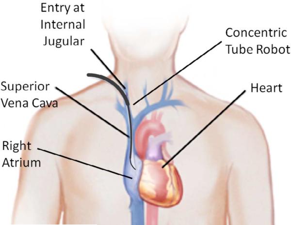
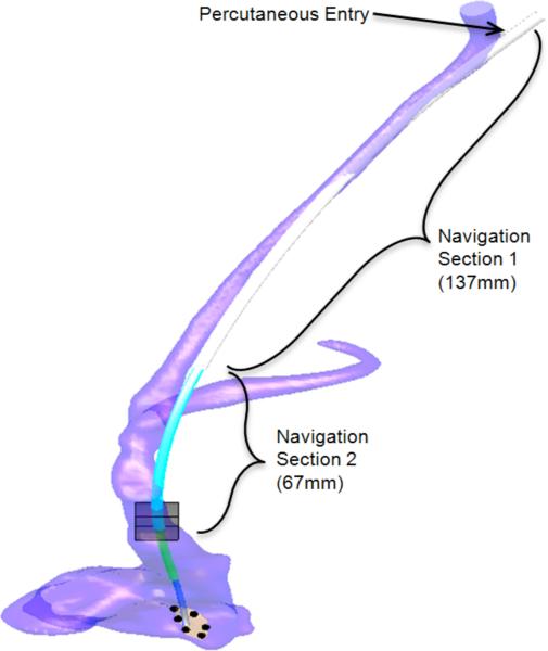
As a specific example, our group performs intracardiac beating-heart repairs with concentric tube robots using fluoroscopic and ultrasound imaging. The robot is introduced to the heart percutaneously via the internal jugular vein as shown in Fig. 2. As the robot is extended telescopically, its tip passes through the internal jugular vein, the right brachiocephalic vein, the superior vena cava and into the right atrium. By experience, we have learned that two constant-curvature sections are sufficient to pass through this sequence of veins into the right atrium. The actual curvature of the vessels suggests that many more robot sections should be necessary, however, it is possible to substantially straighten and laterally move (~1 cm) the vessels during robot insertion. Once the robot has entered the heart, these two proximal robot sections are held fixed while the surgery is performed using the distal sections.
Fig. 2.
Concentric tube robot entering the beating heart via the internal jugular vein.
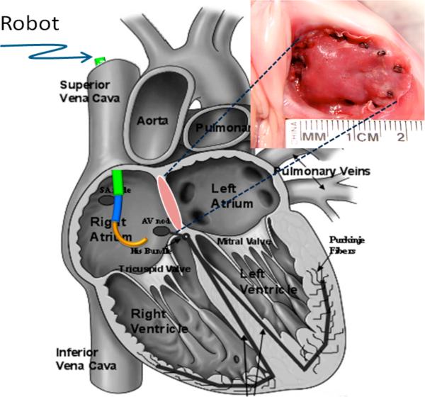
To perform repairs inside the right atrium, we have also demonstrated that two distal sections (one variable curvature and one fixed curvature) are sufficient in many cases. For example, patch closure of an atrial septal defect (ASD) is illustrated in Fig. 3. An atrial septal defect is a hole in the septum that separates the left and right atrium. This hole allows blood returning from the body to be recirculated to the body without being filtered and oxygenated by the lungs.
Fig. 3.
Robotic patch closure of an atrial septal defect. Image top right shows patch applied to porcine heart using tissue anchors.
Our group has developed a beating-heart closure procedure using manual instruments inserted through the cardiac wall in which a fabric patch is attached to the rim around the hole using tissue anchors [8]. In the robotic version of this procedure, the patch is delivered to the right atrium by catheter and is positioned over the septal hole. The robot is then used to insert the anchors around the perimeter of the patch approximately normal to the septal surface.
These task requirements define the manipulation workspace as the set of desired anchor positions and orientations. In contrast to the proximal robot sections in the vasculature, however, the robot sections inside the right atrium are not permitted to press on the atrial wall.
A. Navigation and Manipulation Design Decomposition
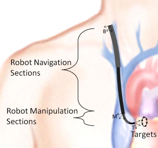
The robot design problem can be posed as a sequence of simpler problems by exploiting the decomposition that divides the robot into a proximal portion responsible for navigation to the surgical site and a distal portion responsible for surgical task performance. The decomposition is depicted in Fig. 4. As shown, the navigation portion of the robot extends between coordinate frames B and M. The manipulation portion of the robot extends from frame M to frame T. The manipulation design problem is solved first and is used to define the navigation design problem as described below.
Fig. 4.
Sketch of navigation and manipulation sections of robot. Coordinate frames on robot correspond to: B = location of percutaneous entry, M = “base” of manipulator and T = manipulator tip frame.
Manipulation Design Problem
Given (i) the desired task workspace, specified as a set of tip positions and orientations and (ii) a manipulator robot architecture (number of sections and type (variable or fixed curvature)), solve for the coordinate frame, M, as well as the curvatures and maximum lengths of the manipulator sections of the robot that minimize:
the curvatures of the manipulator sections, and
the total length of the robot
subject to the following constraints:
all locations in the prescribed workspace are reachable, and
the robot remains within the anatomical constraints of the body lumen.
Having solved for the coordinate frame, M, that positions the manipulation portion of the robot inside the body cavity; the navigation design problem is defined as follows.
Navigation Design Problem
Given (i) the desired entry location into the body, defined by coordinate frame B (Fig.4),(ii) the desired manipulator coordinate frame M and (iii) a navigation robot architecture (number of sections and type (variable or fixed curvature)), solve for the curvatures and lengths of the robot's navigation sections that are of:
minimum curvature, and
minmum total length of the robot
subject to the following constraints:
the navigation sections of the robot start and end at the origins of coordinate frames B and M, respectively, and are also tangent to the frames’ z axes, and
the robot respects the anatomical constraints of the body lumen through which it passes.
As described above, the constraints imposed by the cardiac anatomy differ for the manipulation and navigation sections of the robot. The manipulation portion should avoid contact with the cardiac wall. In contrast, the main constraint on the navigation portion is to avoid vessel puncture during telescopic insertion.
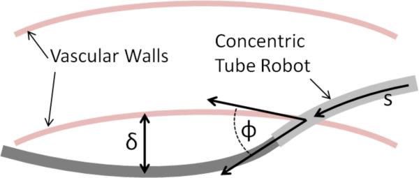
Prior to robot insertion, the vessel is lined with a flexible plastic cannula that protects against vessel abrasion. Consequently, puncture can be characterized, as shown in Fig. 5, by (i) avoiding lateral vessel deformation greater than about 1 cm, and (ii) wherever vessel deformation occurs, the angle between vessel surface tangent and robot axis must be less than ϕ ≈ 20 degrees. To avoid computation of tissue deformation, these criteria can be approximated by comparing the shape of the robot with the undeformed shape of the vessels.
Fig. 5.
Navigation constraints on tangent error ϕ and vessel deformation δ as a function of arc length s along the robot.
III. DESIGN ALGORITHMS
The navigation and manipulation design problems can both be posed as sets of nested, simpler optimization problems in which subsets of the design variables are held constant. The three constitutive optimization problems are (1) solving the anatomically-constrained inverse kinematics problem for a given robot design and base location, (2) solving the robot design problem for a given base location, and (3) solving for the optimal robot base location. Each of these is defined below and then applied to solving the manipulation and navigation design problems.
A. Anatomically-constrained Inverse Kinematics
This problem is to solve for the vector of robot tube rotations and translations, q, (kinematic variables) that position the robot tip at coordinate frame tip at coordinate frame B given that its base is located at frame A while attempting to remain inside anatomical boundaries defined by image . Using homogeneous coordinates to represent coordinate frames, frame B can be written as
| (1) |
Using a penalty method to represent the tip configuration and anatomical constraints, a cost function, c, for this problem can be defined as follows in which overbars indicate fixed parameters.
| (2) |
It is assumed here that the robot has m sections of curvature and maximum length . While not shown explicitly, the design description must designate whether each section is of variable or fixed curvature. For variable curvature sections, the curvature sections κi lies in the interval . The scalar constants k1,k2,k3 are weighting factors. The robot tip frame F(q, Ā) is defined as a function of the kinematic variables and base location.
The first two terms penalize robot tip position error and tip tangent error. Note that an additional tube can always be added to perform tip roll and so only tangent direction is included in the cost function. The third term employs the function Δ to compute the interference between the robot and the anatomy. Minimization of this cost function results in the kinematic variable vector q* that best solves the anatomically-constrained inverse kinematic problem.
| (3) |
B. Robot Design for a Fixed Base Location
This problem involves solving for a robot design that can reach a workspace defined by a set of n tip coordinate frames, Bj, j =1,...,n, while satisfying anatomical constraints.
Mechanics and material properties place limits on the curvature of concentric tube robots [1]. Thus, robot sections with smaller curvatures are preferred. In addition, robot length should be minimized in order to maximize robot stiffness. These lead to the following design cost function, d, that can be written as a function of the constrained inverse kinematic cost function, c.
| (4) |
Here, k4i and k5i are scalar weights on section curvature and length. The optimal design satisfies
| (5) |
C. Combined Base Location and Robot Design
This third problem differs only from the robot design problem in that the robot base coordinate frame A is now a free variable. Thus, its cost function, b, is defined in terms of d as
| (6) |
and its solution is given by
| (7) |
Using these problem definitions, the manipulation and navigation design problem of section II can be posed as follows.
Manipulation Design Problem
This is an example of combined base location and robot design and so can be described using (7),
| (8) |
Since for the robot must avoid deforming the atrial wall, the interference function, Δ, is defined as
| (9) |
Navigation Design Problem
This is an example of robot design for a fixed base location B, and a single workspace configuration, M, and so is given in terms of (5) as
| (10) |
Since the navigation portion can deform the vasculature so long as it does not puncture it, a different interference function from (9) is employed. Using the notation of Fig. 5, the following interference is defined.
| (11) |
Here, arc length, s, is defined as s = 0 at the base frame of the robot, B,and s = L at the distal frame, M.
IV. IMPLEMENTATION
A. Robot Mechanics Model
Current models for tube mechanics are comprised of differential equations with respect to robot arc length that have their boundary conditions split between the robot base and tip [1],[2]. While real-time position control has been demonstrated using this type of model for a specific robot design, computational efficiency was achieved by precomputing the model and fitting a functional approximation [1]. Pre-computation is not possible when iterating on the robot design itself.
Instead, an approximate model is employed here that treats the tubes as torsionally rigid. This model, described by algebraic equations, is much faster to compute [1]. The accuracy of this model for predicting robot shape is quite good for robots that are neither too long nor too curved. The robots in the following design examples fit these constraints.
What the torsionally-rigid model fails to predict accurately are the tube rotation angles in q due to torsional twisting. While q* is an output of the robot design algorithms, these values can be discarded and a more accurate kinematic model can be employed to verify the robot design as given by and to compute accurate values of q*.
B. Anatomical Model
Anatomical models of the vasculature and cardiac chambers were obtained by MRI for a 40 kg pig. Contrast agent was used together with respiratory and cardiac gating to obtain a sequence of 1 mm thick MRI slices. By applying threshold segmentation to each slice, two types of 3D model were created. The first was a 3D binary image of 1 mm resolution that was used to efficiently compute the navigation interference function given by (9). Given the robot modeled as a set of 3D points along its length, (9) was computed by using an interpolation function to map robot coordinates onto the coordinates of the 3D binary model.
The second 3D model generated was a polygonal surface representation. This model was used for visualization (Fig. 6-8) and for computation of the manipulation interference function (11). Function evaluation involved computing nearest neighbors in the polygonal surface model to the points in the robot model. Once the nearest neighbors are identified, the deformation distances, δ, and tangent error angles, ϕ, are straightforward to compute.
Fig. 6.
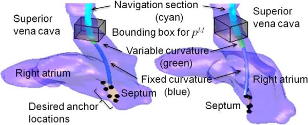
Manipulator design for randomly selected fixed base location inside bounding box. Distal navigation section is shown for visualization purposes.
Fig. 8.
Navigation design optimization. Design minimizes lateral tissue deformation and tangent error along length of sections.
C. Optimization Algorithm
A Generalized Pattern Search (GPS) method, as originally defined in [9], was used to minimize the cost functions given the parameter space. GPS methods are popular in engineering optimization because they do not require any differentiation, and hence are effective in optimizing nonsmooth problems [10]. GPS routines are available in the Matlab® Global Optimization Toolbox.
V. EXAMPLES
The robot design algorithms of section III were implemented for the ASD closure problem detailed in section II using the models and optimization algorithm defined in section IV. The workspace was defined as six points on the septum that correspond to the desired tissue anchor locations. The normal direction to the septum is also included in the workspace description. In practice, it has been found that the anchors deploy well within about 30 degrees of normal.
The coordinate frame, B, for percutaneous entry to the internal jugular vein was surgeon selected based on proximity to the surface in the neck region. To locate the boundary between the manipulation and navigation portions of the robot, a bounding box for pM was defined at the ostium of the superior vena cava as shown in Fig. 6. Recall that pM is the origin of coordinate frame, M, as depicted in Fig. 4. For the examples shown, the z-axis of frame M, given by , was fixed as tangent to the axis of the superior vena cava at its ostium.
A. Manipulator Design
The manipulator design problem defined by (8) and (9) solves for the optimal frame M* and optimal robot design as described by the curvatures and lengths of the m robot sections. For this example, two manipulation robot sections are specified with the proximal section being of variable curvature and the distal section of fixed curvature.
Example 1
A manipulator base location, pM, was randomly selected in the bounding box and the optimal robot design was computed for this fixed M using (4), (5) and (9). Iterative adjustment of the cost function weights resulted in the design shown in Fig. 6 from two orthogonal viewpoints.
The maximum radius of curvature for the proximal variable-curvature section is 18 mm while the distal fixed-curvature section has a radius of curvature of 58 mm. This is physically impractical design since the 18 mm radius of curvature is not feasible. Furthermore, while this design can reach the workspace tip locations, pT, the constraint on approaching normal to the septum cannot be met. The angle between the tip tangent and the septum averages 60 at the six points. This error is too large to ensure correct insertion of the tissue anchors.
Example 2
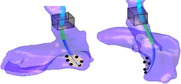
To improve the manipulator robot design obtained in Example 1, its base location, pM, was optimized within the bounding box shown in Fig. 6 using (6), (8), (9). Several iterations of cost function weight adjustment resulted in the design of Fig. 7 shown from two orthogonal viewpoints. The maximum radius of curvature for the proximal variable-curvature section is now 123 mm while the distal fixed-curvature section is 30 mm. These curvatures are within fabrication limits. In addition, the tip normal error at the septum is an acceptable 30 degrees. Maximum required extension lengths for both sections are 24 mm.
Fig. 7.
Manipulator design for optimized location of pM.
Example 3
Using the result of Example 2 to define coordinate frame M, the navigation section of the robot was designed using (4),(10),(11). Recall that the interference function of (11) allows the vasculature to be deformed by the robot during telescopic extension as long as puncture is avoided. Several iterations of cost function weight adjustment resulted in the design of Fig. 8 shown together with the manipulator design of Fig. 7.
The radius of curvature for the proximal navigation section is 286 mm and that of the distal section is 71 mm. These mechanically-feasible curvatures produce a maximum vascular deflection of δ = 9 mm and maximum tangent angle error of ϕ = 16 degrees as defined in Fig. 5.
VI. CONCLUSIONS
The tools described in this paper provide the means to design concentric tube robots for specific procedures and patients. While illustrated here for an application in intracardiac surgery, they can be applied to other parts of the body. They can also be generalized to consider multiple surgical tasks and multiple surgical locations by simply changing the description of the workspace and redefining what sections of the robot are used for manipulation and for navigation.
Acknowledgments
This work was supported by the National Institutes of Health under grants R01HL073647 and R01HL087797.
Contributor Information
Chris Bedell, Mechanical Engineering, Boston University, Boston, MA 02215 USA (bedellch@gmail.com)..
Jesse Lock, Biomedical Engineering, Boston University, Boston, MA 02215 USA (lockj@bu.edu)..
Andrew Gosline, Cardiovascular Surgery, Children's Hospital Boston, Harvard Medical School, Boston, MA 02115 ({Andrew.Gosline}@childrens.harvard.edu)..
Pierre E. Dupont, Cardiovascular Surgery, Children's Hospital Boston, Harvard Medical School, Boston, MA 02115 ({Pierre.Dupont}@childrens.harvard.edu)..
References
- 1.Dupont P, Lock J, Itkowitz B, Butler E. Design and Control of Concentric Tube Robots. IEEE Trans Robotics. 2010;26(2):209–225. doi: 10.1109/TRO.2009.2035740. [DOI] [PMC free article] [PubMed] [Google Scholar]
- 2.Rucker D, Webster R, III, Chirikjian G, Cowan N. Equilibrium Conformations of Concentric-tube Continuum Robots. Int J Robotics Research. 2010;29(10):1263–1280. doi: 10.1177/0278364910367543. [DOI] [PMC free article] [PubMed] [Google Scholar]
- 3.Rucker DC, Jones BA, Webster RJ., III A Geometrically Exact Model for Externally-loaded Concentric-tube Continuum Robots. IEEE Trans Robotics. 2010;26(5):769–780. doi: 10.1109/TRO.2010.2062570. [DOI] [PMC free article] [PubMed] [Google Scholar]
- 4.Lock J, Laing G, Mahvash M, Dupont P. Quasistatic Modeling of Concentric Tube Robots with External Loads. IEEE/RSJ Intelligent Robots and Systems (IROS) 2010:2325–2332. doi: 10.1109/IROS.2010.5651240. [DOI] [PMC free article] [PubMed] [Google Scholar]
- 5.Mahvash M, Dupont P. Stiffness Control of Continuum Surgical Manipulators. IEEE Trans. Robotics. 2011 doi: 10.1109/TRO.2011.2105410. in press. [DOI] [PMC free article] [PubMed] [Google Scholar]
- 6.Lyons L, Webster R, III, Alterovitz R. Motion Planning for Active Cannulas. IEEE/RSJ Int. Conference on Intelligent Robots and Systems, St. Louis. 2009:801–806. [Google Scholar]
- 7.Lyons L, Webster R, III, Alterovitz R. Planning Active Cannula Configurations through Tubular Anatomy. IEEE Int Conf Robotics and Automation, Anchorage. 2010:2082–2087. [Google Scholar]
- 8.Suematsu Y, Martinez JF, Wolf BK, Marx GR, Stoll JA, DuPont PE, Howe RD, Triedman JK, del Nido PJ. Three-dimensional echo-guided beating heart surgery without cardiopulmonary bypass: atrial septal defect closure in a swine model. J Thorac Cardiovasc Surg. 2005;30(5):1348–57. doi: 10.1016/j.jtcvs.2005.06.043. [DOI] [PubMed] [Google Scholar]
- 9.Torzcon V. On the Convergence of Pattern Search Algorithms. SIAM J Optimization. 1997;7(1):1–25. [Google Scholar]
- 10.Audet C, Dennis J., Jr Analysis of Generalized Pattern Searches. SIAM Journal on Optimization. 2003;13(3):889–903. [Google Scholar]


