Abstract
Three-dimensional ultrasound can be an effective imaging modality for image-guided interventions since it enables visualization of both the instruments and the tissue. For robotic applications, its realtime frame rates create the potential for image-based instrument tracking and servoing. These capabilities can enable improved instrument visualization, compensation for tissue motion as well as surgical task automation. Continuum robots, whose shape comprises a smooth curve along their length, are well suited for minimally invasive procedures. Existing techniques for ultrasound tracking, however, are limited to straight, laparoscopic-type instruments and thus are not applicable to continuum robot tracking. Toward the goal of developing tracking algorithms for continuum robots, this paper presents a method for detecting a robot comprised of a single constant curvature in a 3D ultrasound volume. Computational efficiency is achieved by decomposing the six-dimensional circle estimation problem into two sequential three-dimensional estimation problems. Simulation and experiment are used to evaluate the proposed method.
I. Introduction
Automated detection and tracking of robotic instruments is an important problem in minimally invasive surgery. Procedures throughout the body (e.g., in the heart, brain and kidneys) make substantial use of multiple imaging modalities to pre-operatively locate surgical targets and to intra-operatively guide surgical tools. By automatically detecting and tracking instruments in these images, it becomes possible to provide enhanced navigational cues to the clinician in the form of image overlays or virtual fixtures. It also becomes possible to employ image-based servoing to perform certain tasks of a procedure using medical robotics.
Current medical imaging techniques include CT, PET, MRI, fluoroscopy and ultrasound, etc, among which fluoroscopy and ultrasound are widely available realtime imaging systems. While there has been recent progress in the realtime use of MRI [1], [2] to guide robotic surgical procedures, such systems are currently not widely available. Concurrently, however, realtime three-dimensional (3D) ultrasonography has become available for clinical use and its availability is increasing owing to its advantages for interventional tasks [3], [4]. Compared with MRI or CT, ultrasound imaging has a number of advantages, including affordability, portability, patient and clinician safety owing to its use of nonionizing radiation and realtime 3D volumetric imaging of 20 frames per second. The main drawbacks of ultrasonography in contrast to MR and CT imaging are a lower spatial resolution and imaging artifacts.
With the increasing availability of realtime 3D ultrasound, a number of researchers have begun to develop imaging algorithms for enhanced instrument navigation during interventional procedures. For example, tracking algorithms have been developed for instruments consisting of a straight shaft for use in intracardiac surgery [5], [6], [7], liver biopsies [8], prostate brachytherapy [9] and ex-vivo phantom experiments [10].
In addition to tracking handheld instruments, realtime 3D ultrasound also enables the investigation of image-based servoing of minimally invasive surgical robots [11], [6]. In general, only the straight tool shaft was present in the image in these studies. The tracking algorithms were based predominantly on shaft shape and employed linear Principle Component Analysis (PCA) [12], Hough transforms [10] or radon transform line detection [6].
This body of work has assumed the use of laparoscopic-type instruments that consist of a straight shaft. Many surgical robots, however, are continuum robots that curve along their length. This includes robotic catheters [13], [14], robotic instrument sheaths [15], snake-like robots [16] as well as concentric tube robots [17], [18]. While robot curvature is often known in real time based on the kinematic model and sensors, algorithms for detecting and tracking straight robots cannot be easily adapted to robots that curve along their length.
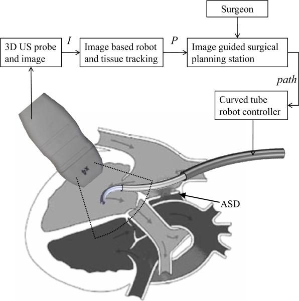
As an example, the schematic of Fig.1 depicts work by the authors in which a concentric tube robot enters the heart through the vasculature under ultrasound guidance to perform intracardiac repairs. The robot is comprised of a telescoping arrangement of tubes in which each section is of approximately constant curvature [18]. While, currently, the robot is controlled teleoperatively, a future goal is to perform some tasks using image-based servoing under clinician supervision as indicated by the block diagram in the figure.
Fig. 1.
Schematic block diagram of proposed 3D ultrasound image servoing of a concentric tube robot inside the heart.
The contribution of this paper is to present a detection algorithm for robots of known constant curvature. Detecting a single constant curvature is of practical value since, given the limited field of view in ultrasound imaging, it is often only the distal curved section of the robot that appears in the image. Furthermore, the detection algorithm proposed here represents the first step toward our long-term goal of detecting and tracking robots of varying curvature in real time.
The remainder of the paper is laid out as follows. Prior work related to tracking techniques in robotic surgery and ultrasound-based instrument tracking are reviewed in the next section. Section III presents the proposed algorithm for automatic detection of constant-curvature robots in 3D ultrasound images. In Sections IV and V, the proposed approach is evaluated using simulation and proof-of-concept experiments. Conclusions appear in the final section.
II. Related work
Multiple sensing modalities are available for tracking surgical instruments, such as optical tracking (OPT), electromagnetic tracking (EMT), image-based tracking [6], ultrasonic sensor tracking (UST) [19], mechanical tracking [20], [21], as well as some hybrid systems integrating two or more modalities [22], [23]. A recent summary of tracking technologies appears in [24].
Novotny et al [6] have classified the previous work for MIS instrument tracking into two categories, imageless external tracking systems and image-based tracking. Imageless external tracking systems generally only track the instrument modeled as a rigid body and neglect any flexing that occurs during tool manipulation inside the body. In addition, imageless tracking systems are not amenable to instrument servoing without employing additional sensing to obtain the relative spatial relationship between the robot tool and the tissue target.
Since image-based tracking systems can track both the target tissue and manipulator from the image simultaneously, they are well suited for automatic guidance of the surgical manipulator to targeted locations on the tissue. Most of the work in this category has focused on tracking needles, catheters or surgical grippers in 2D ultrasound images [25], and recently on tracking the shaft of instruments [10], [12], [6], [8] using 3D ultrasound.
Previous instrument detection techniques using 2D ultrasound images cannot be directly applied to the 3D curved robot detection problem. Furthermore, compared with 3D instrument shaft detection, concentric tube robot detection is different due to both the curvature of the robot and also due to practical limitations. In particular, it requires more parameters to fully represent the geometry of the curved tubular structure. In addition, it is difficult to employ fiducial markers, such as those proposed in [5], to a telescoping arrangement of tubes [18]. To the best of our knowledge, this paper is the first to address the curved robot detection problem using 3D ultrasound images.
Algorithms that have been previously employed for instrument detection from images include the Hough transform [26], the Radon transform [6] and the RANSAC (RANdom SAmple Consensus) algorithm [27]. These are all robust methods for detecting objects described by parameterized models, even in the presence of outliers. There are also variants of the standard Hough transform, such as the generalized Hough transform and the randomized Hough transform [28], among others.
Briefly, the principle of the Hough transform is to map the pixels in image space to parameter space, and then vote for the most likely parameter values by accumulating the evidence in an array, which is termed the accumulator array [29]. At least six parameters (equation (1)) are required to describe a curved robot in 3D space; even if it is simplified as a constant curvature tubular structure. A 6D accumulator array over the parameter space requires a large amount of memory and it is extremely computational intensive to identify the global maxima in 6D space due to the presence of local maxima.
To reduce the complexity of the optimization problem to be solved, we employ 3D volumetric preprocessing followed by a novel two-stage detection technique that reduces the original six-parameter problem into a sequence of two three-parameter problems: Since the constant-curvature arc lies in a plane, we first estimate a three-dimensional normal vector from the origin to the plane. We then project the points onto the plane to estimate the center of the arc and its radius in planar coordinates. This approach is extremely efficient in comparison to the 6D accumulator array formulation and is also flexible in its implementation.
III. Detection Algorithm
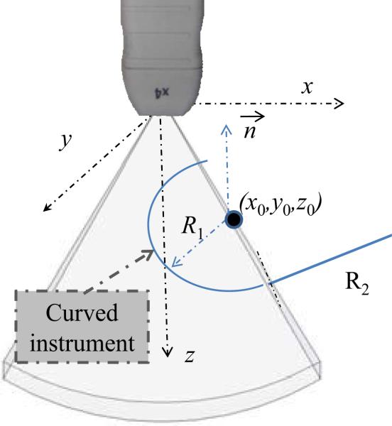
A gray-level ultrasonic volume image, V, is defined as an M × N × P matrix, where v(i, j, k) represents the intensity of the voxel at the ith row, jth column, and kth slice, which corresponds to the Cartesian coordinates of the ultrasound transducer system, as shown in Fig. 2. Here, x represents increasing azimuth, y represents increasing elevation and z indicates increasing distance from the transducer.
Fig. 2.
Ultrasound coordinate system and arc parameters.
As shown in Fig. 2, a circle in Cartesian coordinates of a gray-level ultrasonic volume can be parameterized with six variables, p = [x0, y0, z0, θ, ϕ, R], where X0 = (x0, y0, z0) defines the center of the circle, (θ, ϕ) are the angular parameters describing the unit normal to the circular plane, and R is the radius of the circle. A model for a circle c that employs parameters p can be written as the set of points X = (x, y, z) that lie on the intersection of a sphere and a plane as given by,
| (1) |
where β ∈ [0, π], γ ∈ [0, 2π].
As one of the key steps for curved robot tracking, the algorithm of this section addresses the problem of constant-curvature arc detection, i.e., identifying p from V, based on the partial arc imaged in the limited field-of-view ultrasound image. The following subsections address the three parts of the estimation process. First, image preprocessing is used to remove the effect of imaging artifacts. Subsequently, the estimation of p is performed in two parts. First, the non-unit-length normal vector to the plane of the arc is estimated. The final subsection describes the planar estimation of the center and radius of the arc.
A. Preprocessing
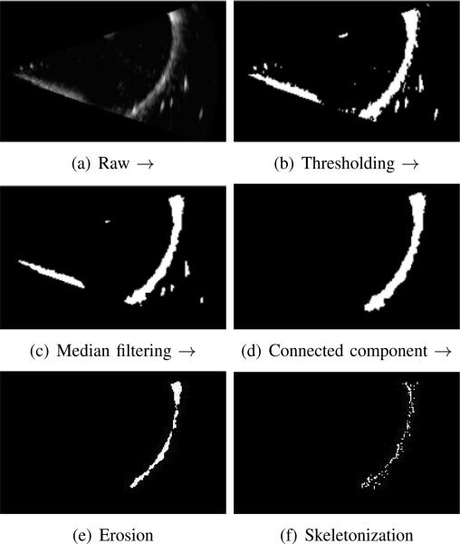
Given our goal of curved robot tracking based on volumetric frame streaming from the 3D ultrasound imaging device, all steps in the detection algorithm should be automated and adaptive to inhomogenity between frames. Image preprocessing is an extremely important step given that ultrasound images are relatively noisy and since instruments produce substantial imaging artifacts. To address these issues, we introduce a five-step pipeline for segmenting a curved robot in any image with sufficient contrast between the robot and background. Clinical examples exhibiting sufficient contrast include instruments inside fluid-filled body lumens or embedded in tissue, e.g., needles. Each step is described below and also is depicted in Figure 3.
Fig. 3.
Preprocessing pipeline for volumetric images using Maximum Intensity Projection (MIP) for visualization. (a) raw image, (b) thresholding, (c) island removal, (d) connected component region growing, (e) morphological erosion and (f) parameter controlled skeletonization.
1) Automatic thresholding
Manual global thresholding is only feasible when the intensity contrast profile is static for all volumetric frames.
2) Median filtering
After the initial step of thresholding, we typically employ a 3D median filter to remove the speckle noise and small isolated islands contained in the thresholded image, which are not desirable for the subsequent target detection. Fig. 3(c) shows the effect after median filtering, where each output voxel contains the median value in the 3 × 3 × 3 windowing neighborhood around the corresponding pixel in the input 3D array.
3) Connected component filter
In this step, the curved robot is assigned a label to differentiate it from its surroundings. A connected component filter performs this task to assign a unique label to all connected voxels. For this volumetric segmentation, a 6-connected neighborhood is used in three-dimensional growing and the largest connected component from the resulted multi-label image is taken as the curved robot, as shown in Fig. 3(d).
4) Morphological erosion
Imaging artifacts cause the apparent cross section of the tube to be substantially larger than the actual diameter and to be noncircular. An erosion filter is applied to trim the robot-labeled portion of the image using a 3D ball-shape structure element with a radius of 2 voxels producing output such as is shown in Fig. 3(e).
5) Skeletonization
The final step of the preprocessing pipeline utilizes a skeletonization algorithm to reduce the 3D labeled structure from the previous step to a curve while preserving its topology [30]. There are many algorithms available for curve-skeleton or centerline construction. Considering computational efficiency, we adopt a parameter-controlled skeletonization based on the distance transform, DTv:
| (2) |
where dist is the distance from the current voxel v(x, y, z) to any voxel (i, j, k) on the set of boundary voxels.
By comparing the distance transform, DTv and the mean of DTv, we can determine if a voxel belongs to the skeleton where the density of the skeleton is controlled by a Thinning Parameter (TP),
| (3) |
The result of the preprocessing is a skeleton of the robot tube as shown in Fig. 3 and the corresponding skeleton voxels in Cartesian coordinates are represented by
| (4) |
Circle detection is now implemented on the skeletonized image by decoupling the six-parameter estimation problem into two three-parameter problems. As described below, the normal vector to the plane containing the circle is first estimated. Then, all points determined to lie in the estimated plane are projected into it for estimation of the radius and center of the planar circle. Finally, the 2D center coordinates are transformed back to obtain the spatial center {x0, y0, z0}.
B. Plane Detection
Despite preprocessing, the skeleton voxels contain outliers that do not describe the instrument arc. Thus, a robust algorithm is needed to estimate the plane of the arc from the skeleton point cloud. A RANSAC algorithm is adopted for this purpose since it can provide good parameter estimates despite a large number of outliers [27]. Furthermore, RANSAC has recently been successfully applied to the localization of straight instrument shafts in 3D ultrasound [27]. The input of our RANSAC plane detector is a set of points, Xs, corresponding to the skeleton points derived from image preprocessing. The outputs of the algorithm are the normal vector to the plane of the arc, , and the subset of X – s that are considered inliers to the detected plane.
Since the RANSAC algorithm is well described in the literature [27] , only a brief description is provided here. The algorithm starts by randomly selecting three points from Xs to calculate the plane parameters. Next, the remaining points in Xs are evaluated for membership in the calculated plane according to a distance threshold. These steps are repeated a fixed number of times to determine the best model fit among all sets of calculated parameters.
C. Circular parameter estimation
Once the plane normal direction and inliers are estimated, the inliers can be projected onto a plane perpendicular to for estimation of the resulting planar circle parameters. Many robust planar circle estimation techniques can be employed here including the Hough transform or RANSAC. We adopt the algorithm proposed in [31] to estimate the circle center and radius. The algorithm minimizes the “approximate mean square distance” metric [31] from data points to a curve defined by implicit equations by solving a generalized eigenvector problem. This approach is fast in comparison with a geometric fit and can provide accurate results even when only a small arc of the circle appears in the image.
IV. Simulation
While our detection algorithm is based on circle parameter estimation, it is often the case that only an arc of the circle is present in the image volume. This occurs not only because of the limited field of view of the ultrasound probe, but also due to the piecewise constant curvature shape of the robot. (Recall Fig. 1.) It can be expected that the estimated parameters of the circle will be less accurate as the central angle of the imaged arc decreases and as image noise increases.
Simulation was employed to evaluate the effect of central angle and image noise on the detection algorithm. This allows us to characterize best-case performance before considering the effects of ultrasound imaging artifacts. Synthetic volumetric images were generated using the following variation of (1) in which represents the null space of are an orthogonal vector pair and α is the central angle parameter of a circular sector.
| (5) |
Volumetric data sets were produced by first using sampled values of α ∈ [αmin, αmax] in (5) to obtain a set of Cartesian points. Zero mean Gaussian noise with variance σ2 was added to the sampled points and the point coordinates were then rounded to the Cartesian coordinates of the imaging volume. Finally, the intensity of these coordinates was set to the maximum value in the image space.
Three metrics were defined to evaluate the detection algorithm. These are the radius estimation error, ∈R, the normal vector misalignment, , and the center estimation error, ∈0, as defined below.
| (6) |
| (7) |
| (8) |
Here, estimated parameters are labeled by , | · | takes the absolute value, and || · || represents the norm of a vector.
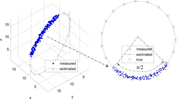
As an example, a ground truth circle was defined by its center, X0 = [10, 10, 10], normal vector, , and radius R = 10. Figure 4 shows the estimation result for a specific image volume corresponding to a quarter circle and noise standard deviation of σ = 0.5. The error metrics for the depicted case are ∈R(90°, 0.5) = 0.26, degrees, and ∈0(90°, 0.5) = 0.83.
Fig. 4.
Circle estimation example using simulated data for a 90° arc and σ = 0.5. The estimated normal and complete circle are shown.
The error metrics were evaluated for eight central angle values and nine values of Gaussian noise standard deviation. The standard deviation of the simplified Gaussian noise was taken to be a fraction of R/10. The results appear in Table I. The lower left corner of the table corresponds to the best estimation conditions of a large central angle and a small noise standard deviation while the upper right corner represents short arcs and high noise. It can be observed that the error metrics become large for α = 45° and . Therefore, in practical applications, we should attempt to ensure that the central angle of the visible portion of the curved instrument in the 3D ultrasound image is at least 45° and σ should be less than 3.3% of the radius.
TABLE I.
Circle estimation error metrics as functions of included angle, α, and Gaussian noise standard deviation, σ.
| 0.11 | 0.22 | 0.33 | 0.44 | 0.55 | 0.66 | 0.77 | 0.88 | 1.0 | ||
|---|---|---|---|---|---|---|---|---|---|---|
| α(deg) | ε | |||||||||
| 45° | ε R | 0.26 | 0.09 | 3.07 | 5.59 | 1.82 | 0.34 | 0.38 | 2.62 | 11.15 |
| ε o | 0.85 | 3.17 | 7.52 | 10.14 | 2.46 | 8.02 | 4.60 | 2.86 | 18.16 | |
| 4.62 | 18.62 | 35.62 | 40.23 | 10.40 | 49.89 | 28.57 | 12.68 | 59.45 | ||
| 90° | ε R | 0.00 | 0.02 | 0.22 | 0.07 | 0.17 | 0.54 | 0.36 | 0.42 | 1.18 |
| ε o | 0.24 | 0.09 | 1.50 | 0.53 | 1.06 | 0.67 | 0.66 | 0.47 | 3.64 | |
| 1.41 | 0.48 | 9.20 | 3.12 | 6.72 | 1.24 | 3.68 | 3.06 | 20.39 | ||
| 135° | ε R | 0.03 | 0.00 | 0.08 | 0.05 | 0.05 | 0.11 | 0.15 | 0.04 | 0.31 |
| ε o | 0.04 | 0.10 | 0.16 | 0.31 | 0.19 | 0.23 | 0.65 | 0.36 | 0.65 | |
| 0.08 | 0.77 | 1.08 | 2.52 | 1.41 | 1.71 | 4.42 | 3.08 | 3.52 | ||
| 180° | ε R | 0.01 | 0.03 | 0.01 | 0.03 | 0.04 | 0.06 | 0.09 | 0.07 | 0.05 |
| ε o | 0.04 | 0.08 | 0.02 | 0.19 | 0.12 | 0.11 | 0.13 | 0.84 | 0.13 | |
| 0.22 | 0.56 | 0.06 | 1.68 | 0.78 | 1.16 | 1.76 | 7.46 | 2.44 | ||
| 225° | ε R | 0.00 | 0.00 | 0.01 | 0.03 | 0.04 | 0.03 | 0.01 | 0.05 | 0.07 |
| ε o | 0.01 | 0.01 | 0.03 | 0.04 | 0.04 | 0.05 | 0.03 | 0.11 | 0.17 | |
| 0.05 | 0.26 | 0.19 | 0.38 | 0.77 | 0.68 | 0.49 | 1.46 | 2.59 | ||
| 270° | ε R | 0.00 | 0.01 | 0.01 | 0.00 | 0.01 | 0.00 | 0.01 | 0.02 | 0.04 |
| ε o | 0.01 | 0.03 | 0.01 | 0.04 | 0.05 | 0.06 | 0.10 | 0.08 | 0.13 | |
| 0.08 | 0.46 | 0.05 | 0.29 | 0.78 | 0.37 | 1.50 | 0.88 | 2.14 | ||
| 315° | ε R | 0.00 | 0.00 | 0.00 | 0.01 | 0.02 | 0.02 | 0.03 | 0.07 | 0.05 |
| ε o | 0.01 | 0.01 | 0.00 | 0.03 | 0.05 | 0.04 | 0.06 | 0.06 | 0.07 | |
| 0.02 | 0.03 | 0.57 | 0.47 | 1.37 | 0.44 | 0.48 | 0.19 | 2.78 | ||
| 360° | ε R | 0.00 | 0.01 | 0.01 | 0.02 | 0.01 | 0.00 | 0.01 | 0.01 | 0.00 |
| ε o | 0.00 | 0.01 | 0.02 | 0.03 | 0.02 | 0.05 | 0.01 | 0.09 | 0.05 | |
| 0.02 | 0.10 | 0.76 | 0.58 | 0.74 | 0.48 | 1.51 | 0.40 | 0.17 | ||
V. Experiments
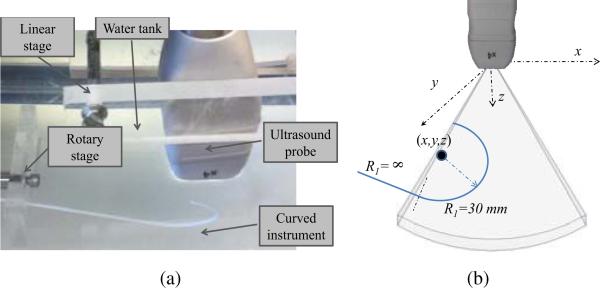
Experiments were performed in a water tank as shown in Fig. 5. Three dimensional ultrasound images were acquired using a Philips SONOS 7500 (www.philips.com) with an X4 probe. The probe was mounted as shown in a linear stage while a piecewise constant curvature rod was submerged and mounted on a rotary stage. By adjusting the linear and rotary stages, the position and orientation of the instrument with respect to the probe can be controlled. The bottom of the tank was lined with a rubber pad to reduce reverberation.
Fig. 5.
Water tank experimental design. (a) Photograph, (b) Curved instrument parameters.
The curved instrument rod was fabricated from a photopolymer by 3D printing to ensure accurate control of curvature. As shown, its distal region had a radius of curvature of R1 = 30 mm and a central angle of α = 180°. Its proximal length was straight (R2 = ∞). The rod diameter was 2 mm.
Standard settings of the imaging parameters were used during image generation, including 50% overall gain, 50% compression rate, frequency fusion mode 2, high density scan line spacing, 9 cm image depth, and zero dB power level.
The 3D ultrasound image volumes can either be recorded to a CD or streamed to a computer for further processing. The streaming module was implemented in C++ and the detection algorithm was coded in MATLAB (MathWorks, Natick, MA).
Three types of experiments were performed to evaluate the proposed detection algorithm. First, the preprocessing pipeline was tested by comparing it with manual segmentation. Next, the parameter estimation method was tested by generating a linear probe motion with respect to the instrument rod and evaluating the error in the estimated instrument path. Finally, ex vivo validation was performed by submerging a porcine heart in the water tank and placing the curved portion of the instrument inside the right atrium. Each set of experiments is described below.
A. Preprocessing algorithm
To evaluate the preprocessing pipeline of curved instrument segmentation, we performed a comparison of ten automatically labeled instruments with those that were labeled manually. The volumetric overlap metric (Dice metric, defined as twice the intersection of two volumes over the combined set) was used to evaluate the comparison,
| (9) |
where A and B are the instrument volumes labeled automatically and manually, respectively, and |·| computes the number of voxels. The results of the ten comparisons are plotted in Figure 6. With an average Dice value greater than 0.91, the proposed preprocessing algorithm is capable of sufficiently accurate segmentation to enable robust parameter estimation using the techniques described in the following sections.
Fig. 6.
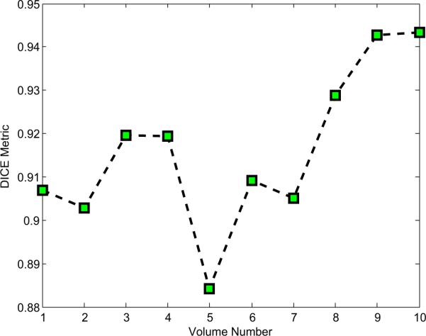
Plot of Dice (volumetric overlap) metric comparing preprocessing algorithm and manual labeling for ten ultrasound images.
B. Parameter Estimation
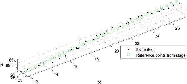
In this experiment, the instrument rod was fixed in position and the probe was translated with respect to it back and forth in the x direction using the linear stage shown in Fig. 5. Ten independent experiments were conducted to examine the trajectory estimation performance. The probe mounted on the translational stage was moved in a step size of 0.5 mm for each volume sample. The resolution of the translation stage is 0.01 mm. Registration was performed by aligning the base frames of the translation stage and ultrasound transducer, and calculating the translation offset by sampling the paired points.
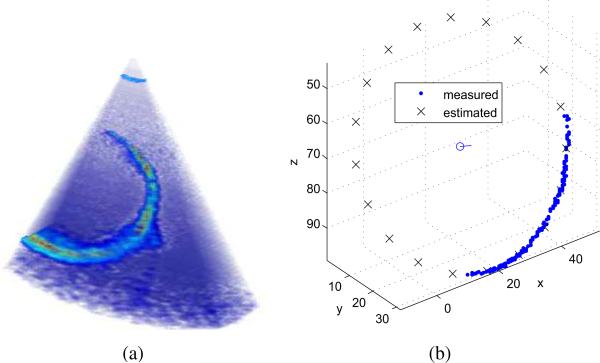
A typical detection example is shown in Fig. 7 and the estimated path of the circle's center is plotted in Fig. 8. The average values of the error metrics for this path were ∈R = 2.3 ± 1.5 mm, degrees, and ∈0 = 2.1 ± 1.1 mm.
Fig. 7.
Parameter estimation example. (a) Ultrasound image as acquired. (b) Detection algorithm output including skeleton data set, estimated circle and center.
Fig. 8.
Actual and estimated instrument path corresponding to probe motion along its x axis. Units are in mm.
C. Ex vivo imaging
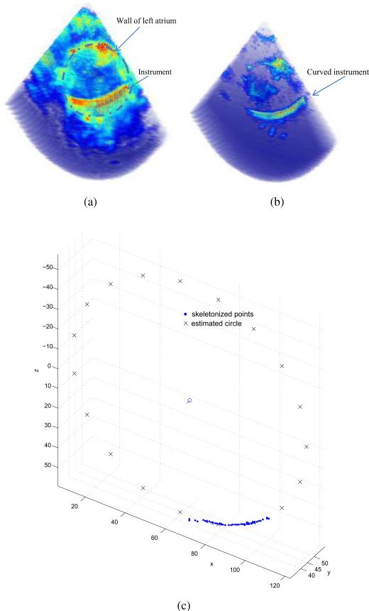
It is more difficult to visualize instruments inserted inside the body rather than in a water tank. To determine if the proposed algorithm is applicable to a clinical situation, a porcine heart was submerged in the water tank and the curved instrument was inserted inside the left atrium. Since tissue and instruments have substantially different acoustic impedance values, it is possible to tune the acquisition parameters of the ultrasound system for each. In particular, by reducing the power level, the acoustic reflections from the tissue are substantially reduced while those of the instrument remain sufficient for imaging. This effect is demonstrated in Fig. 9. The estimated instrument curve is also shown.
Fig. 9.
Images of the instrument inserted inside a porcine heart. (a) Tissue optimized image. (b) Instrument optimized image. The instrument appears as indicated by the arrow. (c) Estimated circle.
VI. Conclusions and future work
This paper investigates the problem of automatic curved robot detection from realtime 3D ultrasound images, and represents our first step toward achieving realtime tracking and image-based servoing of continuum robots. Our proposed algorithm includes a preprocessing pipeline for automatically extracting the curved robot from ultrasound volumetric images. It then applies a novel two-stage approach to decompose the six parameter curve estimation problem into a sequence of two three-parameter problems. Efficacy of the algorithm was demonstrated through simulation and experiment.
The current algorithm is limited to detection of a single segment of constant curvature at the distal end of the robot. While this is directly applicable to many clinical situations given the limited field of view of 3D ultrasound systems, our goal is to extend the approach to multiple connected segments of constant curvature. Since both the RANSAC plane detector and subsequent circular parameter estimator are parallelizable algorithms, we plan to develop a real-time tracking method using GPU (Graphical Processing Unit) computing and by taking advantage of the known kinematic trajectory as prior information in the estimation process.
ACKNOWLEDGMENT
The authors gratefully acknowledge the assistance of Scott Settlemier, Philips Medical Systems, and the useful discussions with colleagues Andrew Gosline and Genevieve Laing.
This work was supported by the National Institutes of Health under grants R01HL073647 and R01HL087797.
References
- 1.Hashizume M, Yasunaga T, Tanoue K, Ieiri S, Konishi K, Kishi K, Nakamoto H, Ikeda D, Sakuma I, Fujie M, Dohi T. New real-time MR image-guided surgical robotic system for minimally invasive precision surgery. International Journal of Computer Assisted Radiology and Surgery. 2008;2(6):317–325. [Google Scholar]
- 2.Kapoor A, Wood B, Mazilu D, Horvath K, Li M. MRI-compatible hands-on cooperative control of a pneumatically actuated robot. Robotics and Automation, 2009. ICRA ’09. IEEE International Conference on. IEEE; 2009; pp. 2681–2686. [DOI] [PMC free article] [PubMed] [Google Scholar]
- 3.Cannon J, Stoll J, Salgo I, Knowles H, Howe R, Dupont P, Marx G, del Nido P. Real-time three-dimensional ultrasound for guiding surgical tasks. Computer aided surgery. 2003;8(2):82–90. doi: 10.3109/10929080309146042. [DOI] [PubMed] [Google Scholar]
- 4.Yagel S, Cohen SM, Shapiro I, Valsky DV. 3d and 4d ultrasound in fetal cardiac scanning: a new look at the fetal heart. Ultrasound Obstet Gynecol. 2007;29(1):81–95. doi: 10.1002/uog.3912. [DOI] [PubMed] [Google Scholar]
- 5.Stoll J, Dupont P. Passive markers for ultrasound tracking of surgical instruments. Medical Image Computing and Computer-Assisted Intervention–MICCAI 2005. 2005:41–48. doi: 10.1007/11566489_6. [DOI] [PubMed] [Google Scholar]
- 6.Novotny P, Stoll J, Vasilyev N, Del Nido P, Dupont P, Zickler T, Howe R. GPU based real-time instrument tracking with three-dimensional ultrasound. Medical image analysis. 2007;11(5):458–464. doi: 10.1016/j.media.2007.06.009. [DOI] [PMC free article] [PubMed] [Google Scholar]
- 7.Yuen S, Kettler D, Novotny P, Plowes R, Howe R. Robotic motion compensation for beating heart intracardiac surgery. The International Journal of Robotics Research. 2009;28(10):1355. doi: 10.1177/0278364909104065. [DOI] [PMC free article] [PubMed] [Google Scholar]
- 8.Boctor EM, Choti MA, Burdette EC, Webster RJ., III Three-dimensional ultrasound-guided robotic needle placement: an experimental evaluation. The International Journal of Medical Robotics and Computer Assisted Surgery. 2008;4(2):180–191. doi: 10.1002/rcs.184. [DOI] [PMC free article] [PubMed] [Google Scholar]
- 9.Yan P. MO-FF-A4-02: Automatic Shape-Based 3D Level Set Segmentation for Needle Tracking in 3D TRUS Guided Prostate Brachytherapy. Medical Physics. 2010;37:3366. doi: 10.1016/j.ultrasmedbio.2012.02.011. [DOI] [PubMed] [Google Scholar]
- 10.Ding M, Cardinal HN, Guan W, Fenster A. Mun SK, editor. Automatic needle segmentation in 3d ultrasound images. 2002;4681(1):65–76. SPIE. [Google Scholar]
- 11.Stoll J, Novotny P, Howe R, Dupont P. Real-time 3d ultrasound-based servoing of a surgical instrument. Robotics and Automation, 2006. ICRA 2006. Proceedings 2006 IEEE International Conference on. IEEE.pp. 613–618. [Google Scholar]
- 12.Stoll J. Ph.D. dissertation. Boston University; 2007. Ultrasound-based navigation for minimally invasive medical procedures. [Google Scholar]
- 13.Saliba W, Reddy V, Wazni O, Cummings J, Burkhardt J, Haissaguerre M, Kautzner J, Peichl P, Neuzil P, Schibgilla V, et al. Atrial fibrillation ablation using a robotic catheter remote control system: Initial human experience and long-term follow-up results. Journal of the American College of Cardiology. 2008;51(25):2407. doi: 10.1016/j.jacc.2008.03.027. [DOI] [PubMed] [Google Scholar]
- 14.Konstantinidou M, Koektuerk B, Wissner E, Schmidt B, Zerm T, Ouyang F, Kuck K-H, Chun JK. Catheter ablation of right ventricular outflow tract tachycardia: a simplified remote-controlled approach. 2011;13(5):696–700. doi: 10.1093/europace/euq510. [DOI] [PubMed] [Google Scholar]
- 15.Choset H, Zenati M, Ota T, Degani A, Schwartzman D, Zubiate B, Wright C. Enabling medical robotics for the next generation of minimally invasive procedures: Minimally invasive cardiac surgery with single port access. Surgical Robotics: Systems, Applications, and Visions. 2010:257. [Google Scholar]
- 16.Simaan N, et al. Design and integration of a telerobotic system for minimally invasive surgery of the throat. The International journal of robotics research. 2009;28(9):1134. doi: 10.1177/0278364908104278. [DOI] [PMC free article] [PubMed] [Google Scholar]
- 17.Rucker D, Webster R, Chirikjian G, Cowan N. Equilibrium conformations of concentric-tube continuum robots. The International Journal of Robotics Research. 2010;29(10):1263. doi: 10.1177/0278364910367543. [DOI] [PMC free article] [PubMed] [Google Scholar]
- 18.Dupont P, Lock J, Itkowitz B, Butler E. Design and control of concentric-tube robots. Robotics, IEEE Transactions on. 2010;26(2):209–225. doi: 10.1109/TRO.2009.2035740. [DOI] [PMC free article] [PubMed] [Google Scholar]
- 19.Lin H-H, Tsai C-C, Hsu J-C. Ultrasonic localization and pose tracking of an autonomous mobile robot via fuzzy adaptive extended information filtering. IEEE Trans. on Instrumentation and Measurement. 2008 Sept.57(9):2024–2034. [Google Scholar]
- 20.Bax J, Cool D, Gardi L, Knight K, Smith D, Montreuil J, Sherebrin S, Romagnoli C, Fenster A. Mechanically assisted 3D ultra-sound guided prostate biopsy system. Medical Physics. 2008;35(12):5397–5410. doi: 10.1118/1.3002415. [DOI] [PubMed] [Google Scholar]
- 21.Teber D, Baumhauer M, Guven EO, Rassweiler J. Robotic and imaging in urological surgery. Current Opinion in Urology. 2009;19(1):108–113. doi: 10.1097/MOU.0b013e32831a4776. [DOI] [PubMed] [Google Scholar]
- 22.Ren H, Kazanzides P. Investigation of attitude tracking using an integrated inertial and magnetic navigation system for hand-held surgical instruments. IEEE/ASME Transactions on Mechatronics. 2010 [Google Scholar]
- 23.Nakamoto M, Sato Y, Miyamoto M, Nakamjima Y, Konishi K, Shimada M, Hashizume M, Tamura S. 3D ultrasound system using a magneto-optic hybrid tracker for augmented reality visualization in laparoscopic liver surgery. Medical Image Computing and Computer-Assisted Intervention (MICCAI) 2002:148–155. [Google Scholar]
- 24.Peters T, Cleary K. Image-Guided Interventions: Technology and Applications. Springer; 2008. [DOI] [PubMed] [Google Scholar]
- 25.Ortmaier T, Vitrani M-A, Morel G, Pinault S. Robust real-time instrument tracking in ultrasound images for visual servoing. Robotics and Automation, 2005. ICRA 2005. Proceedings of the 2005 IEEE International Conference on; 2005.pp. 2167–2172. [Google Scholar]
- 26.Ogundana OO, Coggrave CR, Burguete RL, Huntley JM. Fast hough transform for automated detection of spheres in three-dimensional point clouds. Optical Engineering. 2007;46(5):051002. [Google Scholar]
- 27.Uhercik M, Kybic J, Liebgott H, Cachard C. Model fitting using ransac for surgical tool localization in 3-d ultrasound images. Biomedical Engineering, IEEE Transactions on. 2010;57(8):1907–1916. doi: 10.1109/TBME.2010.2046416. [DOI] [PubMed] [Google Scholar]
- 28.Torii A, Imiya A. The randomized-hough-transform-based method for great-circle detection on sphere. Pattern Recogn. Lett. 2007 July;28:1186–1192. [Google Scholar]
- 29.Rizon M, Yazid H, Saad P. Geometric Modeling and Imaging, 2007. GMAI ’07; 2007. A comparison of circular object detection using hough transform and chord intersection; pp. 115–120. hough. [Google Scholar]
- 30.Parameter-controlled volume thinning. Graphical Models and Image Processing. 1999;61(3):149–164. [Google Scholar]
- 31.Taubin G. Estimation of planar curves, surfaces, and nonplanar space curves defined by implicit equations with applications to edge and range image segmentation. IEEE Transactions on Pattern Analysis and Machine Intelligence. 1991;13(11):1115–1138. [Google Scholar]


