Abstract
Objective
To assess the performance of a high-definition CT (HDCT) for imaging small caliber coronary stents (≤ 3 mm) by comparing different scan modes of a conventional 64-row standard-definition CT (SDCT).
Materials and Methods
A cardiac phantom with twelve stents (2.5 mm and 3.0 mm in diameter) was scanned by HDCT and SDCT. The scan modes were retrospective electrocardiography (ECG)-gated helical and prospective ECG-triggered axial with tube voltages of 120 kVp and 100 kVp, respectively. The inner stent diameters (ISD) and the in-stent attenuation value (AVin-stent) and the in-vessel extra-stent attenuation value (AVin-vessel) were measured by two observers. The artificial lumen narrowing (ALN = [ISD - ISDmeasured]/ISD) and artificial attenuation increase between in-stent and in-vessel (AAI = AVin-stent - AVin-vessel) were calculated. All data was analyzed by intraclass correlation and ANOVA-test.
Results
The correlation coefficient of ISD, AVin-vessel and AVin-stent between the two observers was good. The ALNs of HDCT were statistically lower than that of SDCT (30 ± 5.7% versus 35 ± 5.4%, p < 0.05). HDCT had statistically lower AAI values than SDCT (15.7 ± 81.4 HU versus 71.4 ± 90.5 HU, p < 0.05). The prospective axial dataset demonstrated smaller ALN than the retrospective helical dataset on both HDCT and SDCT (p < 0.05). Additionally, there were no differences in ALN between the 120 kVp and 100 kVp tube voltages on HDCT (p = 0.05).
Conclusion
High-definition CT helps improve measurement accuracy for imaging coronary stents compared to SDCT. HDCT with 100 kVp and the prospective ECG-triggered axial technique, with a lower radiation dose than 120 kVp application, may be advantageous in evaluating coronary stents with smaller calibers (≤ 3 mm).
Keywords: Stent, Coronary artery, Phantom, CTA
INTRODUCTION
While stent implantation is a successful treatment for coronary heart disease, 5-46% of coronary stents develop restenosis (1-4). Consequently, a noninvasive and available method of stent follow-up becomes more important and indispensable. Recently, it was found that 64-row multi-slice coronary CT angiography (CCTA) plays an important role in the assessment of coronary artery and coronary stent imaging (5-9). Despite advances in technology, the evaluation of coronary stents with conventional multi-detector row, standard-definition computed tomography (SDCT) at a spatial resolution of 0.33-0.50 mm in-plane spatial resolution and a contrast resolution of 5 mm, is limited; and stents less than 3 mm in diameter are not routinely interpretable in CCTA (1, 2, 10, 11).
Recently a high-definition CT (HDCT) scanner, composed of a data acquisition system with a high sampling rate, X-ray tube with the deflecting focal spot technique, and a new gemstone detector, was introduced to significantly improve the in-plane spatial resolution to 0.23 mm and a contrast resolution to 3 mm. Therefore, the purpose of this phantom study was to assess the imaging performance of HDCT for imaging coronary stents with smaller calibers (≤ 3 mm) by comparing it with conventional 64-row SDCT. Imaging performance was also evaluated according to the various conditions including tube voltage and scan mode.
MATERIALS AND METHODS
Coronary Artery Models and Stents
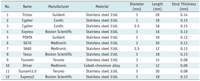
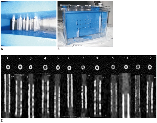
Acrylonitrile-butadiene-styrene resin (ABS resin) material with a CT value of 40 Hounsfield units (HU) that is similar to that of a vessel wall was chosen to simulate the coronary artery. All the vessel models had an inner diameter of 3 mm and were filled with contrast material (iopamidol 350, Bracco, Italy) diluted to 300 HU. Twelve commercially available stents (Table 1) were inserted into the coronary artery models. Closed at both ends, the coronary artery models were fixed by a plastic cement plate with the long axis of the model corresponding to the z-axis. The models with expanded stents were then positioned in a plastic container filled with water (Fig. 1).
Table 1.
Characteristics of Stents
Fig. 1.
Coronary artery models and stents.
A. Closed at both ends, coronary artery models are fixed by plastic cement plate with long axis of model corresponding to z-axis. B. Models with expanded stents are positioned in plastic container filled with water. C. Transaxial and reconstructed sagittal images of all 12 stents on high-definition CT scanned with 120 kVp, 450 mA of phantom. Stent characteristics are listed in Table 1.
CT Scanning Protocols
Using the ECG monitoring machine mimicking a stable heart rate of 60 beats per minute, a series of two scan modes, including a prospective ECG-triggered axial (PTA) CCTA and retrospective ECG-gated helical (RGH) CCTA were performed. A series of 16 scans were performed on HDCT (Discovery CT750 HD, GE Healthcare, Waukesha, WI) and a SDCT (LightSpeed VCT XT, GE Healthcare, Waukesha, WI) was performed separately with the same parameters: two scan modes (PTA and RGH), two tube voltages (120 kVp and 100 kVp) and four tube currents (450 mA, 350 mA, 250 mA, 150 mA for 120 kVp and 650 mA, 550 mA, 450 mA, 350 mA for 100 kVp). In addition, a prospective axial acquisition on HDCT (100 kV, 250 mA) and a prospective axial acquisition on SDCT (100 kV, 750 mA) were also performed.
Other scan parameters include a section thickness of 0.625 mm and a gantry rotation speed of 350 ms. The helical pitch for the RGH mode was 0.22. For the PTA mode, datasets were acquired at 75% of the R-R interval with a padding time of 125 ms.
Images were reconstructed at 75% of the cardiac phase on a 512 × 512 pixels matrix size with a display field of view of 9.6 cm for analyzing stents. Sharp convolution kernels were chosen for stent imaging (12, 13): "HD detail" for HDCT group and "detail" for SDCT group.
Imaging Analysis
All images were analyzed by two radiologists specialized in cardiovascular imaging with 3 years experience each, blinded with the CT protocols on a separate workstation (Advantage Workstation version 4.4, GE Healthcare, Waukesha, WI). The observers measured inner stent diameter (ISD) using electronic calipers, attenuation values (AV) inside the visible stent lumen, and attenuation values inside the non-stented lumen of vessel models using a region of interest (ROI) technique. All the measurements were performed on the plane perpendicular to the long-axis of the vessel on each image using the workstation semiautomatic software Vessel Analysis (Advantage Workstation with CardIQ software, version 4.4, GE Healthcare, Milwaukee, WI). The size of the ROI was drawn as small as possible to avoid the stent struts and artifacts. The measurements were repeated 3 times, and the median was selected. Images were displayed with a window level/width of 450/1200.
The artificial lumen narrowing (ALN) was calculated with the following equation: ALN = (ISD - ISDmeasured)/ISD (14, 15). The artificial attenuation increase (AAI) between in-stent and in-vessel were also calculated with the following equation: AAI = AVin-stent - AVin-vessel.
Radiation Dose
With the dose-length product (DLP) displayed on the CT system, the effective dose (E) was calculated with the following equation: E = k × DLP, where k is a conversion coefficient for the anatomical region examined (i.e., 0.014 mSv mGy-1cm-1 for the chest) (16).
Statistical Analyses
All the data from the 34 series were analyzed with the SPSS 13.0 software (Chicago, IL). Inter-observer variability for the measurement of diameter and attenuation was tested by a two-way model intraclass correlation coefficient. A one-factor ANOVA test was used to compare the effects of the scanner and stent caliber on the measurement of stent imaging, and imaging between the two scan modes or tube voltage in each group of HDCT or SDCT were compared by a two-factor ANOVA test. A two-sided significance level of 0.05 was used in all the analyses.
RESULTS
Interobserver Agreement
The intraclass correlation coefficient of ISD (0.89 for SDCT group, 0.92 for the HDCT group), AVin-vessel (0.93 for SDCT group, 0.90 for the HDCT group), and AVin-stent (0.85 for SDCT group, 0.88 for the HDCT group) between the two observers was good.
CT Scanner
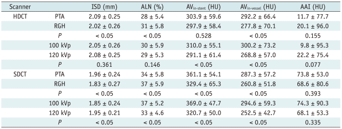
The results of the measured diameter, attenuation, ALN, and AAI are shown in Table 2. The one-factor ANOVA revealed that there was a statistical difference of the measured inner stent diameter between HDCT and SDCT (p < 0.05). Also, the ALN for the HDCT group was significantly lower than that of the SDCT group (p < 0.05). No statistical difference in AVin-vessel was found between HDCT and SDCT (p = 0.345). On the other hand, HDCT had a statistically lower AVin-stent (p < 0.05) combined with a significant lower AAI value than SDCT (p < 0.05).
Table 2.
Comparison of Measurements between HDCT and SDCT
Note.- All values are presented as mean ± standard deviation. AAI = artificial attenuation increase between in-stent and in-vessel, ALN = artificial lumen narrowing, AV = attenuation value, HDCT = high-definition CT, ISD = inner stent diameter, HU = Hounsfield unit, SDCT = standard-definition CT
Stent Diameter
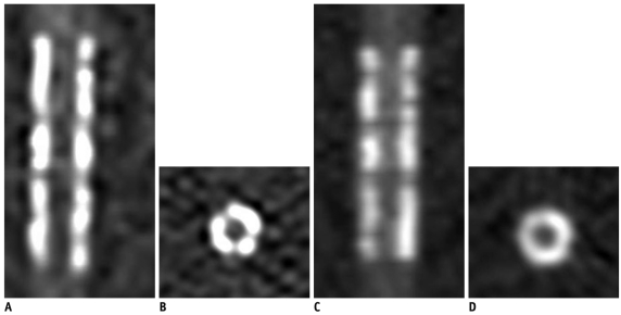
Comparing measurements of 2.5 mm and 3 mm diameter stents separately, the one-factor ANOVA also revealed that all the measurement values of HDCT were significantly better than that of SDCT for both the 2.5 mm and 3.0 mm diameter stents (Table 3) (Fig. 2).
Table 3.
Comparison between HDCT and SDCT for 2.5 mm and 3 mm Diameter Stents
Note.- All values are presented as mean ± standard deviation. AAI = artificial attenuation increase between in-stent and in-vessel, ALN = artificial lumen narrowing, AV = attenuation value, HDCT = high-definition CT, HU = Hounsfield unit, ISD = inner stent diameter, SDCT = standard-definition CT
Fig. 2.
Coronal and axial images of stent No 6 (S670, Medtronic) acquired with 120 kVp and 450 mA on high-definition CT (A, B) and standard-definition CT (C, D), respectively. Stent lumen on images of high-definition CT is better observed when combined with better lumen measurement.
Scan Mode
For both HDCT and SDCT, a significant difference was found for ALN between the scan modes (p < 0.05), the ALN of the prospective axial group was lower than that of the retrospective helical group. However, there was no difference in AAI between the two scan modes on both HDCT and SDCT (Table 4).
Table 4.
Comparison between Two Scan Modes and Tube Voltages in Each Datasets of HDCT and SDCT
Note.- All values are presented as mean ± standard deviation. AAI = artificial attenuation increase between in-stent and in-vessel, ALN = artificial lumen narrowing, AV = attenuation value, HDCT = high-definition CT, ISD = inner stent diameter, PTA = prospective ECG-triggered axial, RGH = retrospective ECG-gated helical, SDCT = standard-definition CT
Tube Voltage
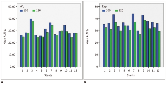
For tube voltages of 100 kVp and 120 kVp, there was no difference of ALN on HDCT (p = 0.146) whereas there was a difference of ALN on SDCT (p < 0.05) (Fig. 3).
Fig. 3.
For tube voltages of 100 kVp and 120 kVp, no difference in artificial lumen narrowing on high-definition CT (A) and significant difference of artificial lumen narrowing (ALN) on standard-definition CT (B) is found.
No difference of AAI between 100 kVp and 120 kVp on both HDCT and SDCT was found.
Radiation Dose
The effective doses were 2.26 ± 1.9 mSv versus 2.38 ± 2.1 mSv (p = 0.867) for acquisition on HDCT vs. acquisition on SDCT; 0.69 ± 0.22 mSv versus 4.16 ± 1.31 mSv (p < 0.05) for PTA versus RGH acquisition; and 2.29 ± 1.91 mSv versus 2.36 ± 2.1 mSv (p = 0.926) for datasets of 100 kVp versus data sets of 120 kVp.
DISCUSSION
In our study, the ALN and the AAI of both 2.5 mm and 3 mm diameter stents were lower on HDCT than that on SDCT. On both HDCT and SDCT, the ALN of the prospective acquisition was lower than that of retrospective acquisition. Concerning tube voltage, contrary to ALN on SDCT, there was no difference in ALN between the 100 kVp and 120 kVp on HDCT.
Despite advances in technology, SDCT remains limited for the assessment of coronary artery stents, especially for stents less than 3 mm in diameter (1, 2, 10, 11, 13, 16-18). The evaluation of coronary artery stents has been considerably impaired by various artifacts, such as artificial lumen narrowing and increased in-stent attenuation.
Actually, the major advancement of multi-slice CT is the optimization of spatial and temporal resolution which can be helpful in coronary artery stent imaging. Recently, dual-source CT with significant higher temporal resolution, but identical spatial resolution (0.33 mm), has been clinically introduced. However, even with its higher temporal resolution, reliable stent evaluation is restricted to larger stent diameters. In the study by Maintz et al. (19), the majority of 3 mm diameter stents exhibited a lumen visibility of 50-59% on dual-source CT.
The blooming artifact is one of the major obstacles for coronary artery stent imaging. Resulting from a combination of partial volume averaging and beam hardening effect, it creates a spillover effect from higher CT attenuation voxels to adjacent lower voxels, which leads to obscuring the coronary artery lumen, degrade the in-stent visibility, as well as provide ALN and AAI (18). Therefore, the higher spatial resolution of 0.23 mm of HDCT probably provides a clue in improving the assessment of a coronary artery stent less than 3 mm in diameter, as the ALN and AAI values of HDCT were significantly lower than that of SDCT in our study.
Designing a CT scanner for high resolution imaging such as HDCT means evaluating the components that drive image acquisition, which include the data acquisition system (DAS), the X-ray tube, and the detector. The HD DAS has the capability to deliver 2496 VPR (views per rotation) for all rotation speeds, which allows for a reduction in the uncertainty of the position of an object in order to bring higher resolution. By deflecting the focal spot, the new HD tube changes the sampling pattern to enable multiple looks at the same object, while gaining higher resolution and not increasing the dose. A newly developed gemstone detector is made from a complex rare earth based oxide, which has a chemically replicated garnet crystal structure. The Gemstone detector has both a primary decay time of only 30 nanoseconds and lower afterglow levels, which has the direct effect of decreasing in-plane spatial resolution.
Consistent with previous studies (14, 15, 20), our study demonstrated that the measurements of coronary artery stent images from PTA acquisition is significantly better than that from RGH. There are two potential explanations of the artifact reductions by PTA scans. First, the axial scan uses real data for imaging reconstruction without interpolation, which is especially helpful for smaller objects. Second, the PTA scan uses a 180° fan beam angle, while the RGH uses interpolated 180° data (20).
On the other hand, higher tube voltage can likely play a role in decreasing the blooming artifact (21). However, there was no statistical difference for ALN between 100 kVp and 120 kVp datasets on HDCT in our study. To our knowledge, no tube voltage value had been widely accepted as standard for coronary stent imaging, although 120 kVp was mainly used. Horiguchi et al. (14) reported that 140 kVp provided better coronary in-stent visibility than 120 kVp with the prospective axial technique, but no statistical difference in ALN was found in their study among the 140 kVp and 120 kVp groups. Our results revealed that HDCT with 100 kVp may be advantageous in lowering dose for evaluating coronary stents while maintaining the same imaging quality.
The following limitations of our study must be mentioned. First, the visibility of the stent lumen is influenced strongly by the stent material, stent diameter, strut thickness, and design. Early stent designs, having greater strut thickness and made of metals such as tantalum and gold, are more difficult to detect by MDCT compared to the newer stents with much thinner struts and made predominantly of stainless steel, cobalt chromium, and nitinol. However, the type of stent material analyzed in this study was limited (Stainless steel 316 L and Cobalt-chromium alloy). Second, since the focus of our study was the impact of spatial resolution on coronary artery stent imaging, the impact of temporal resolution was not mentioned. Therefore the phantom used in this study was static and no specific heart rate had been simulated.
In conclusion, high-definition CT offers improved measurement accuracy for imaging coronary stents compared to conventional SDCT. HDCT with a combination of 100 kVp and the prospective ECG-triggered axial technique may be advantageous in evaluating coronary stents with smaller calibers (≤ 3 mm) and lower dose.
References
- 1.Holmes DR, Jr, Leon MB, Moses JW, Popma JJ, Cutlip D, Fitzgerald PJ, et al. Analysis of 1-year clinical outcomes in the SIRIUS trial: a randomized trial of a sirolimus-eluting stent versus a standard stent in patients at high risk for coronary restenosis. Circulation. 2004;109:634–640. doi: 10.1161/01.CIR.0000112572.57794.22. [DOI] [PubMed] [Google Scholar]
- 2.Morice MC, Colombo A, Meier B, Serruys P, Tamburino C, Guagliumi G, et al. Sirolimus- vs paclitaxel-eluting stents in de novo coronary artery lesions: the REALITY trial: a randomized controlled trial. JAMA. 2006;295:895–904. doi: 10.1001/jama.295.8.895. [DOI] [PubMed] [Google Scholar]
- 3.Fischman DL, Leon MB, Baim DS, Schatz RA, Savage MP, Penn I, et al. A randomized comparison of coronary-stent placement and balloon angioplasty in the treatment of coronary artery disease. Stent Restenosis Study Investigators. N Engl J Med. 1994;331:496–501. doi: 10.1056/NEJM199408253310802. [DOI] [PubMed] [Google Scholar]
- 4.King SB, 3rd, Smith SC, Jr, Hirshfeld JW, Jr, Jacobs AK, Morrison DA, Williams DO, et al. 2007 focused update of the ACC/AHA/SCAI 2005 guideline update for percutaneous coronary intervention: a report of the American College of Cardiology/American Heart Association Task Force on Practice guidelines. J Am Coll Cardiol. 2008;51:172–209. doi: 10.1016/j.jacc.2007.10.002. [DOI] [PubMed] [Google Scholar]
- 5.Seifarth H, Ozgun M, Raupach R, Flohr T, Heindel W, Fischbach R, et al. 64- versus 16-slice CT angiography for coronary artery stent assessment: in vitro experience. Invest Radiol. 2006;41:22–27. doi: 10.1097/01.rli.0000191365.88345.e1. [DOI] [PubMed] [Google Scholar]
- 6.Das KM, El-Menyar AA, Salam AM, Singh R, Dabdoob WA, Albinali HA, et al. Contrast-enhanced 64-section coronary multidetector CT angiography versus conventional coronary angiography for stent assessment. Radiology. 2007;245:424–432. doi: 10.1148/radiol.2452061389. [DOI] [PubMed] [Google Scholar]
- 7.Schuijf JD, Pundziute G, Jukema JW, Lamb HJ, Tuinenburg JC, van der Hoeven BL, et al. Evaluation of patients with previous coronary stent implantation with 64-section CT. Radiology. 2007;245:416–423. doi: 10.1148/radiol.2452061199. [DOI] [PubMed] [Google Scholar]
- 8.Ehara M, Surmely JF, Kawai M, Katoh O, Matsubara T, Terashima M, et al. Diagnostic accuracy of 64-slice computed tomography for detecting angiographically significant coronary artery stenosis in an unselected consecutive patient population: comparison with conventional invasive angiography. Circ J. 2006;70:564–571. doi: 10.1253/circj.70.564. [DOI] [PubMed] [Google Scholar]
- 9.Cademartiri F, Schuijf JD, Pugliese F, Mollet NR, Jukema JW, Maffei E, et al. Usefulness of 64-slice multislice computed tomography coronary angiography to assess in-stent restenosis. J Am Coll Cardiol. 2007;49:2204–2210. doi: 10.1016/j.jacc.2007.02.045. [DOI] [PubMed] [Google Scholar]
- 10.Wykrzykowska JJ, Arbab-Zadeh A, Godoy G, Miller JM, Lin S, Vavere A, et al. Assessment of in-stent restenosis using 64-MDCT: analysis of the CORE-64 Multicenter International Trial. AJR Am J Roentgenol. 2010;194:85–92. doi: 10.2214/AJR.09.2652. [DOI] [PMC free article] [PubMed] [Google Scholar]
- 11.Windecker S, Serruys PW, Wandel S, Buszman P, Trznadel S, Linke A, et al. Biolimus-eluting stent with biodegradable polymer versus sirolimus-eluting stent with durable polymer for coronary revascularisation (LEADERS): a randomised non-inferiority trial. Lancet. 2008;372:1163–1173. doi: 10.1016/S0140-6736(08)61244-1. [DOI] [PubMed] [Google Scholar]
- 12.Maintz D, Seifarth H, Raupach R, Flohr T, Rink M, Sommer T, et al. 64-slice multidetector coronary CT angiography: in vitro evaluation of 68 different stents. Eur Radiol. 2006;16:818–826. doi: 10.1007/s00330-005-0062-8. [DOI] [PubMed] [Google Scholar]
- 13.Suzuki S, Furui S, Kaminaga T, Yamauchi T, Kuwahara S, Yokoyama N, et al. Evaluation of coronary stents in vitro with CT angiography: effect of stent diameter, convolution kernel, and vessel orientation to the z-axis. Circ J. 2005;69:1124–1131. doi: 10.1253/circj.69.1124. [DOI] [PubMed] [Google Scholar]
- 14.Horiguchi J, Fujioka C, Kiguchi M, Yamamoto H, Kitagawa T, Kohno S, et al. Prospective ECG-triggered axial CT at 140-kV tube voltage improves coronary in-stent restenosis visibility at a lower radiation dose compared with conventional retrospective ECG-gated helical CT. Eur Radiol. 2009;19:2363–2372. doi: 10.1007/s00330-009-1419-1. [DOI] [PubMed] [Google Scholar]
- 15.Suzuki S, Furui S, Kuwahara S, Mehta D, Kaminaga T, Miyazawa A, et al. Coronary artery stent evaluation using a vascular model at 64-detector row CT: comparison between prospective and retrospective ECG-gated axial scans. Korean J Radiol. 2009;10:217–226. doi: 10.3348/kjr.2009.10.3.217. [DOI] [PMC free article] [PubMed] [Google Scholar]
- 16.Mahesh M, Cody DD. Physics of cardiac imaging with multiple-row detector CT. Radiographics. 2007;27:1495–1509. doi: 10.1148/rg.275075045. [DOI] [PubMed] [Google Scholar]
- 17.Halliburton SS. Options for reducing patient radiation dose with cardiovascular computed tomography. Int J Cardiovasc Imaging. 2009;25:153–164. [Google Scholar]
- 18.Kerl JM, Schoepf UJ, Vogl TJ, Ackermann H, Vogt S, Costello P, et al. In vitro evaluation of metallic coronary artery stents with 64-MDCT using an ECG-gated cardiac phantom: relationship between in-stent visualization, stent type, and heart rate. AJR Am J Roentgenol. 2010;194:W256–W262. doi: 10.2214/AJR.09.2318. [DOI] [PubMed] [Google Scholar]
- 19.Maintz D, Burg MC, Seifarth H, Bunck AC, Ozgun M, Fischbach R, et al. Update on multidetector coronary CT angiography of coronary stents: in vitro evaluation of 29 different stent types with dual-source CT. Eur Radiol. 2009;19:42–49. doi: 10.1007/s00330-008-1132-5. [DOI] [PubMed] [Google Scholar]
- 20.Yang WJ, Pan ZL, Zhang H, Pang LF, Guo Y, Chen KM. Evaluation of coronary artery in-stent restenosis with prospectively ECG-triggered axial CT angiography versus retrospective technique: a phantom study. Radiol Med. 2011;116:189–196. doi: 10.1007/s11547-010-0599-8. [DOI] [PubMed] [Google Scholar]
- 21.Horiguchi J, Kiguchi M, Fujioka C, Shen Y, Arie R, Sunasaka K, et al. Radiation dose, image quality, stenosis measurement, and CT densitometry using ECG-triggered coronary 64-MDCT angiography: a phantom study. AJR Am J Roentgenol. 2008;190:315–320. doi: 10.2214/AJR.07.2191. [DOI] [PubMed] [Google Scholar]


