Abstract
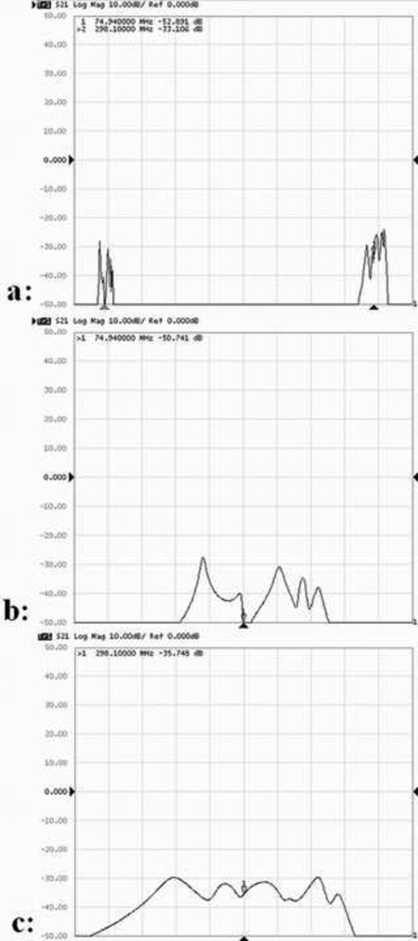
In this work, an 8-element by 8-element dual-tuned quadrature volume coil with a mix of capacitor terminated half-wavelength (λ/2) and quarter-wavelength (λ/4) microstrip resonators is proposed for multinuclear MRI/S studies at 7T. In the proton channel, λ/2 microstrip resonators with capacitive terminations on both ends are employed for operation at higher frequency of 298.1 MHz; in the heteronucleus channel, capacitor terminated λ/4 resonators, suitable for low frequency operations, are used to meet the low frequency requirement. This mixed structure design is particularly advantageous for high field heteronuclei MR applications with large difference in Larmor frequency of the nuclei in question. The proposed design method makes it much easier to perform frequency tuning for heteronucleus channel using a variable capacitor with a practical capacitance range. As an example, a dual-tuned volume coil for 1H/13C mouse spectroscopic imaging was proposed to demonstrate the feasibility of this method. The finite-difference time-domain (FDTD) method is first used to model this dual-tuned volume coil and calculate the B1 field distributions at two frequencies. Transmission parameters (S21) measured between the proton channel and the carbon channel are −50 dB at 75 MHz and −35 dB at 298 MHz, showing the excellent isolation between the two channels at 7T. The proton image and 13C FID CSI image of a corn oil phantom on the axial plane at 7T demonstrate the feasibility of the proposed method. A preliminary proton image of a mouse on the sagittal plane is also acquired using the proposed dual-tuned volume coil at 7T, illustrating a fairly uniform B1 field and sufficient image coverage for imaging in mice.
Keywords: Dual-tuned, Microstrip, Volume coil, 7T, mouse imaging, MRI/S
1. Introduction
Due to low natural abundance of heteronuclei, leading to low signal intensity, multinuclear MR applications, such as 1H/13C [1–5], 1H/23Na [6–8] and 1H/31P [9–12] spectroscopic imaging that are capable of depicting metabolic process in vivo, have brought forward urgent demand for efficient double-frequency RF coils to utmost detect the MR signals. Dual-tuned RF coils have been designed using different techniques such as lumped element method [13–18] and transverse electromagnetic resonator (TEM) technique [19–21], and have demonstrated great advantages in multinuclear spectroscopic imaging. However, involvement of two independently controlled frequencies makes the design of dual-tuned RF coils complicated and technically challenging, particularly at high and ultrahigh fields due to the required high frequency [22]. The high operation frequency of the ultrahigh field MR results in the increased conductor/radiation losses, degraded quality factors, augmented electromagnetic interactions between the two resonant frequencies, and difficulties in achieving required high resonant frequency of RF coils. These problems are more prominent in the presence of a living animal loaded to RF coils.
In recent years, it has been demonstrated that microstrip transmission line (MTL) RF coils are advantageous to high field in vivo MR applications with high quality factor, high frequency operation capability, reduced radiation losses, and thus improved MR sensitivity. This technique has been successfully applied to designs of surface coils [23,24], volume coils [25–28], and coil array [23,29–35] for high and ultrahigh field MR applications in humans. Because of the high frequency property of the microstrip resonator and the behavior of resonator length dependence of the frequency, the microstrip coil design shows challenges in reducing the resonant frequency for heteronuclear MR studies especially for the small animal applications where the coil size is much smaller than that used in humans. The capacitive termination [25,26,29] is one of methods to reduce the resonant frequency. However, in many multinuclear MR studies, the Larmor frequency of the heteronucleus is much lower than that of proton. It often requires impractically large capacitance to tune the resonant frequency down to the Larmor frequency of the heteronucleus in question. This makes its frequency tuning difficult and potentially increases the interaction between proton and heteronuclear channels.
To take advantage of the microstrip resonator and overcome the technical design difficulties facing in practical designs, we propose a design method for dual-tuned quadrature volume coil using a mix of capacitor terminated half-wavelength (λ/2) and quarter-wavelength (λ/4) microstrip resonators for multinuclear MR studies at ultrahigh fields. Compared with λ/2 microstrip resonators, λ/4 resonators with the same physical length operate at significantly lower frequency. This low frequency feature of λ/4 resonators is well suitable for heteronuclear MR applications. To demonstrate the proposed design technique, we have designed a 16-element dual-tuned volume coil in which 8 elements are λ/2 microstrip resonators for 1H channel while another set of 8 elements are λ/4 microstrip resonators for 13C channel. This volume coil is capable of quadrature driving for both 13C channel and 1H channel for improved sensitivity and reduced RF power for spin excitation. The resonant frequency of the λ/4 resonator is only half of that of the λ/2 resonator, therefore the terminated capacitor of the λ/4 resonator for 13C channel can be greatly reduced, making the frequency tuning much easier [36]. The finite-difference time-domain (FDTD) method is used to model the dual-tuned volume coil, determine the capacitance and calculate the B1 field distributions at the two frequencies. Bench tests and in vivo MR experiments are performed to validate the feasibility and performance of the proposed 7T dual-tuned volume coil design.
2. Materials and methods
2.1 Dual-tuned microstrip volume coil design for 1H and 13C MRI/S
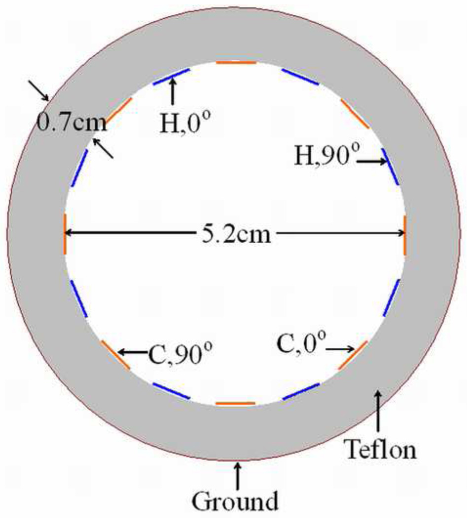
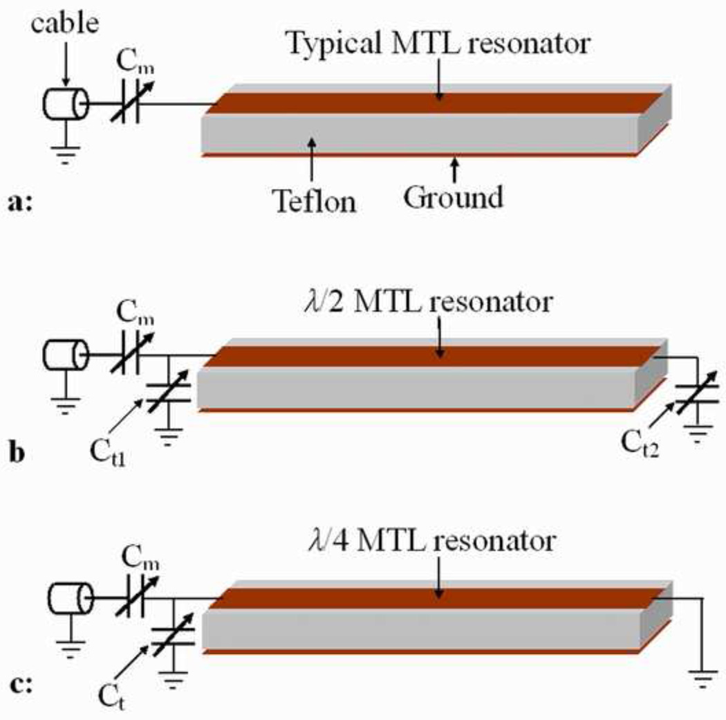
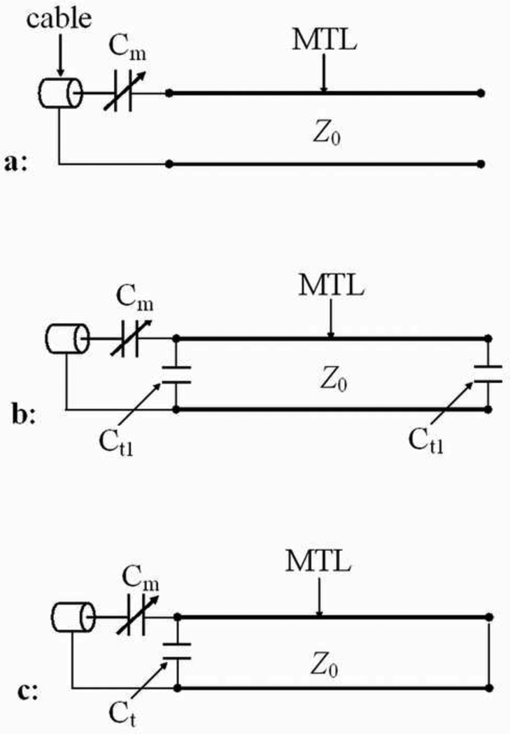
The dual-tuned quadrature microstrip volume coil was designed for 1H imaging and 13C spectroscopy at 7T, corresponding to the resonant frequencies of 298.1 MHz and 75 MHz respectively. A cross-sectional view of the volume coil is shown in Fig.1. There are totally 16 microstrip elements of 8 λ/2 resonators for 1H and 8 λ/4 resonators for 13C equidistantly distributed on a Teflon cylinder which serves as both dielectric substrate and mechanical support. These 8 λ/2 resonators and 8 λ/4 resonators are alternately placed along the Teflon cylinder. Teflon is a low loss dielectric material with loss tangent smaller than 0.0002 and a permittivity of 2.1 at the frequency of interest and has been used as substrate for microstrip surface coil. The dimensions of this cylinder are 6.6cm OD by 5.2 cm ID by 10.1 cm in length. On the inner surface of the Teflon cylinder, 8 microstrip conductors of 1H channel and 8 microstrip conductors of 13C channel were interleaved built. Each microstrip conductor was made from a copper tape with 0.32 cm width and 36 µm thickness (3M, St. Paul, Minnesota). The structure and equivalent circuit of the elements of 1H channel and 13C channel are illustrated in Fig.2 and Fig. 3 respectively, as well as those of the typical microstrip resonator for comparison. For the typical microstrip resonator, the resonant frequency is:
| (1) |
where l and c denote the length of the microstrip conductor and the velocity of light in free space, respectively. εeff is the effective permittivity of the microstrip resonator.
Figure 1.
The cross-sectional view of the dual-tuned quadrature microstrip volume coil with mixed λ/2 and λ/4 resonators. The λ/2 and λ/4 resonators are alternately arranged along the circumference of the cylindrical volume coil. With this structure, both channels can be driven in quadrature for improved SNR and reduced excitation power.
Figure 2.
Diagrams of (a) typical open-circuited MTL resonator, (b) capacitor terminated λ/2 MTL resonator and (c) capacitor terminated λ/4 MTL resonator.
Figure 3.
Equivalent circuits of (a) the typical open-circuited MTL resonator, (b) capacitor terminated λ/2 MTL resonator and (c) capacitor terminated λ/4 MTL resonator.
For the 1H channel, a λ/2 microstrip resonator with capacitive termination on both ends was adopted. The resonant frequency of such a λ/2 resonator can be predicted by solving the following equation [26]:
| (2) |
where Ct1 and Ct2 are the capacitance of the termination capacitors of the microstrip resonator shown in Fig.2b. Z0 is the characteristic impedance of the microstrip resonator. Compared with Eq. (1) of the typical microstrip resonator, the resonant frequency can be significantly reduced for the same conductor length l. This enables the microstrip volume coil to be designed for small size coil.
For the 13C channel, a capacitor terminated λ/4 microstrip resonator was adopted. The resonant frequency of such a structure can be deduced by calculating the limitation of the Eq. (2). Thus the resonant frequency of the capacitor terminated λ/4 microstrip resonator can be predicted by solving the following equation:
| (3) |
where Ct is the capacitance of the termination capacitor of the microstrip resonator shown in Fig.2c. Compared with Eq. (2), the resonant frequency can be significantly reduced for the same capacitance and conductor length. This makes it possible to apply the microstrip resonator to 13C which has a much lower resonant frequency than 1H.
The ground plane of the coil was built by ringing a cylindrical copper foil with 36 µm thickness on the outer surface of the Teflon cylinder. This continuous ground plane can effectively enhance the coupling between the elements.
The resonant frequency of the microstrip volume coil is expressed as [26]:
| (4) |
where k1, i+1 is the mutual inductance between the 1st element and the (i+1)th elements, N denotes the number of elements and L denotes the inductance of each microstrip resonant element. In this volume coil design the magnetic coupling dominates the coupling between the elements, therefore the electric coupling was ignored and only mutual inductance to coil induced voltage from the other resonator elements was considered. The resonant element frequency fre denotes that of the 1H channel or the 13C channel. From Eq. (4), it can be seen that the resonant frequency of the volume coil is smaller than that of each element due to the mutual coupling between them.
2.2 FDTD simulations
Based on the structure described above, a coil model was first built and the B1 field distributions at the two frequencies were numerically simulated using the FDTD. A cylinder-shaped mouse muscle phantom with permittivity of 58 and conductivity of 0.8 was modeled within a 16-element dual-tuned microstrip volume coil. The diameter of the phantom was 4.2 cm which is about 80% of the volume coil ID. Each element of the coil was modeled as a 0.32 cm wide and 10.1 cm long thin strip of copper and placed equal spacing on the surface of a cylinder with 5.2 cm ID, 6.6 cm OD and 10.1 cm length. The permittivity of this cylinder is 2.1, which is the same as that of the Teflon. On the inside surface of this cylinder the ground plane of the volume coil was modeled as a continuous wrapping copper with thickness of 0.36 µm. For the mixed λ/2 resonator of 1H channel, capacitors were connected on both ends of the copper strip as passive load. For the mixed λ/4 resonator of 13C channel, on one end the strip was directly connected to the ground plane using a copper strip with the same width of the strip; on the other end a capacitor was connected between the strip and the ground using a perfect electric conductor. The coaxial cable of the volume coil was modeled as a series voltage source with 50 ohm impedance which was connected to each driven port of the coil model. Linear drive was used for each channel. The Yee cell was 1 mm which was small enough for satisfying the simulation accuracy. The Gauss waveform was used to determine the value of the terminated capacitors and the stop criteria were that the calculation converged to −35 dB or reached the maximum iteration number of 106. Then, the Sine waveform was used to calculate the B1 field distributions and the stop criteria were that the calculation converged to −40 dB or the iteration number reached 300,000. All the FDTD calculation was performed using the software XFDTD 6.4 (Remcom, Inc.) on a PC with 2.33 GHz CPU and 4 GB memory.
To investigate the RF efficiency and field homogeneity of our proposed design, a conventional 16-strut dual-tuned birdcage coil was modeled and compared with the microstrip coil model. The conventional birdcage was in the same size as the microstrip coil: the diameter was 5.2 cm and the length was 10.1 cm. 8 struts of 1H channel and 8 struts of 13C channel were alternately placed. Each strut was made from a copper tape with 0.32 cm width and 36 um thickness (3M, St. Paul, Minnesota). The capacitor value for 1H channel was 7.4 pF while that for 13C channel was 59 pF. The same phantom was modeled within the coil. All the other settings for the FDTD simulation were kept the same.
2.3 Bench test
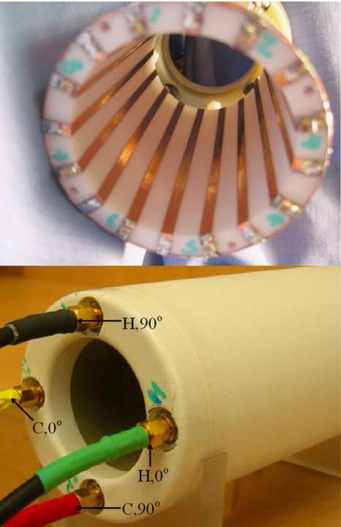
Based on the simulation results, a dual-tuned microstrip volume coil for 1H and 13C was then built as shown in Fig.4. To generate a circularly polarized B1 field, the coil operated in quadrature with connection to a 3-dB 90° quadrature hybrid. In both 1H and 13C channels, two driving elements of the volume coil were 90° apart in phase. The frequency tuning of the two channels can be achieved by adjusting the termination capacitors. The impedance matching of the volume coil can be achieved by varying the trimmer capacitor (Voltronics, Denville, NJ) which was connected in series to the microstrip conductors of the driving element.
Figure 4.
(a) Structure of the proposed 8-element by 8-element dual-tuned volume coil using alternately placed λ/2 and λ/4 microstrip resonators for in vivo 13C/1H MRSI applications at 7T and (b) Prototype of this dual-tuned microstrip volume coil with two sets of quadrature feedings.
An Agilent E5070B network analyzer was used for testing the coil resonance modes, the isolation between two quadrature ports and that between the proton and carbon channels. As shown in Fig.1, there are totally 4 ports on the dual-tuned volume coil: 0° 1H port, 90° 1H port, 0° 13C port and 90° 13C port. The resonance modes of the 4 ports were tested using the reflection parameter S11 firstly. Then the isolation between two pair of quadrature ports of 1H channel and 13C channel were tested using the transmission parameter S21. To test the isolation between the 1H and 13C channels, the S21 between them was also measured at both resonant frequencies.
2.4 Phantom and in vivo MRI
Both phantom and in vivo images were tested using a commercial 7T General Electric Signa™ scanner. In the phantom experiment, the 1H images and 13C spectroscopic images of a cylindrical corn coil phantom were obtained in axial plane. The 1H image of the phantom was acquired using a gradient echo (GRE) sequence with FOV =10 cm, encoding matrix = 256×128, slice thickness = 3 mm, TR= 100 ms, TE= 6.8 ms, FA = 30° and Average number = 1. The 13C spectroscopic image was acquired using the FIDCSI sequence (GE Healthcare, Waukesha, WI, USA) with TR = 2 sec, 10 mm in plane slice and 20 mm thickness. The FIDCSI is 2D chemical shift imaging by using a set of phase-encoded free induction decay signals. A proton image of a mouse was also acquired in sagittal plane using a fast spin echo (FSE) sequence with the following imaging parameters: FOV = 9 cm, encoding matrix = 192×192, slice thickness = 1.6 mm, TR= 4000 ms, TE= 104.08 ms, FA = 90° and Average number = 1.
3. Results
3.1 simulations
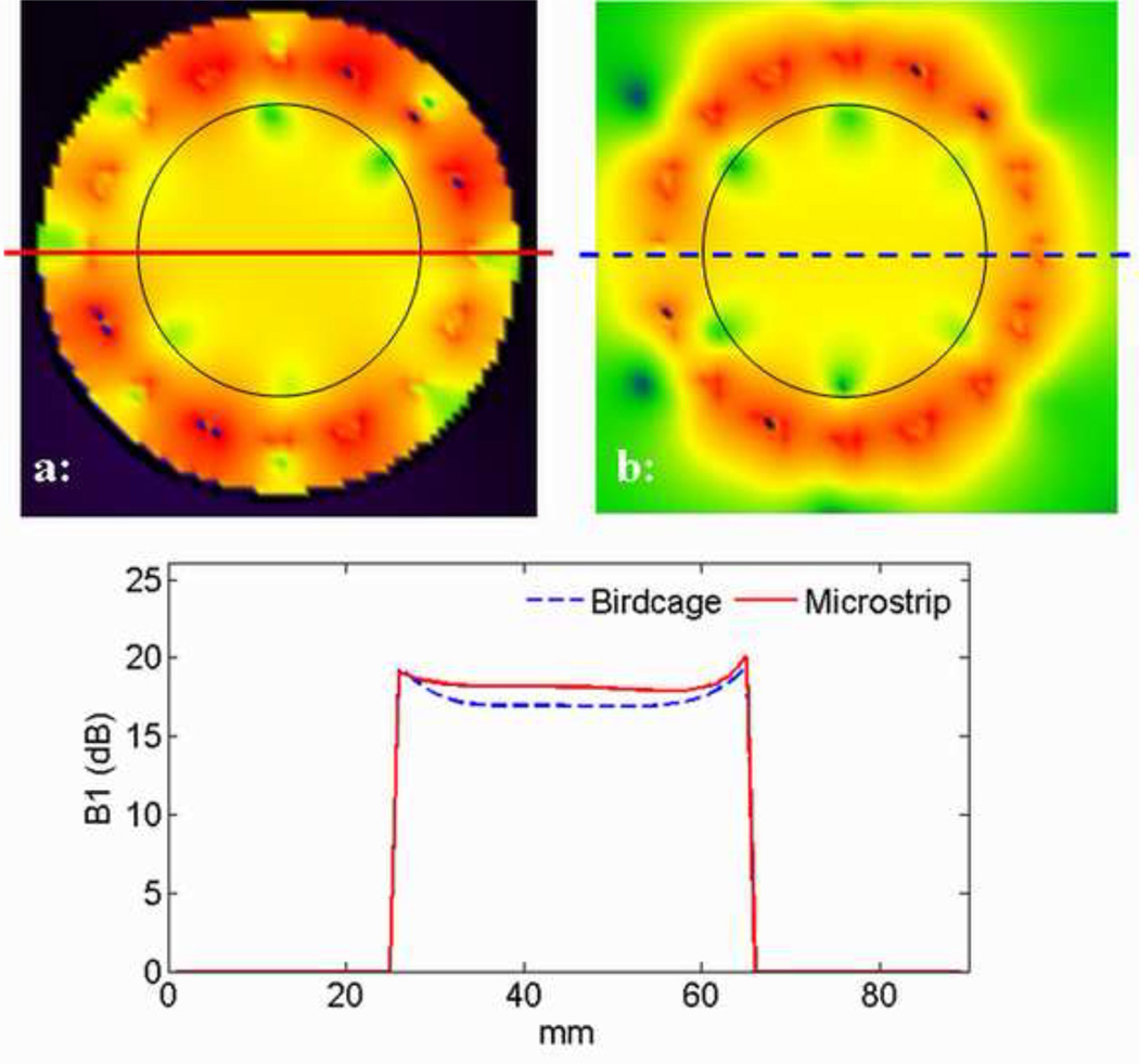
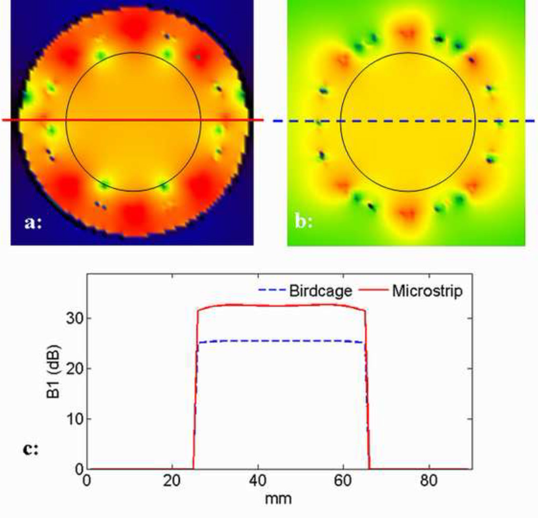
Theoretical calculation based on the analytical equations was first applied to estimate the capacitance for each element of the 1H and 13C channel. Then these estimated capacitances were used to build the numerical model for the dual-tuned microstrip volume coil in xFDTD environment and the Gauss waveform was used to sweep frequency to determine the value of each capacitor. After several iterations, proper capacitances were found: for the λ/2 resonator in 1H channel the terminated capacitors are 13.6 pF and 6.8 pF, and for the λ/4 resonator in 13C channel the terminated capacitance was 70 pF. Using this setting, the sine waveform was used to calculate the B1 field distribution of each channel. Both the 1H channel and 13C channel generate a homogeneous RF field within the interested area of the phantom. As shown in Fig.5a, when the 298.1 MHz sine wave signal was input into the driven port of the 1H channel, the elements of the 1H channel were all excited except the elements which were orthogonal to the driven element, while all the elements of the 13C channel were suppressed. When the 75 MHz Sine waveform was used, the 13C channel excited and the 1H channel was quiet, which is shown in Fig.6a. The sinusoid distributions of the currents for both 1H and 13C channels along the circumference of the coil are clearly illustrated. These results show excellent isolation between 1H and 13C channels, which is desired in dual-tuned RF coil design.
Figure 5.
B1 field distributions of the 1H channel of (a) microstrip dual-tuned volume coil and (b) conventional dual-tuned birdcage coil calculated using FDTD method. (c) 1D plot of the field distribution along the central line of the 2D images. The red line denotes the microstrip coil while the blue line denotes the birdcage coil. The RF efficiency of the microstrip coil is around 1 dB higher than that of the birdcage coil, while the homogeneity variation of both coils is within 1.8 dB range.
Figure 6.
B1 field distributions of the 13C channel of (a) microstrip dual-tuned volume coil and (b) conventional dual-tuned birdcage coil calculated using FDTD method. (c) 1D plot of the field distribution along the central line of the 2D images. The red line denotes the microstrip coil while the blue line denotes the birdcage coil. The RF efficiency of the 13C channel of the microstrip coil is around 6 dB higher than that of the birdcage coil, while the homogeneity variation of both coils is within 1 dB range.
Fig.5b shows the RF field distribution of the 1H channel of the 16-strut dual-tuned birdcage coil. Compared with Fig.5a, the RF field of the birdcage coil used in this work is slightly weaker than that of the microstrip. The 1D plot in Fig.5c shows this difference more clearly. The RF efficiency of the 1H channel of the microstrip volume coil is approximately 1 dB higher than that of the birdcage coil, while the homogeneity variation of both coils are within 1.8 dB range. As a comparison of Fig.6a which shows the 13C RF field distribution of the microstrip volume coil, Fig.6b shows that of the conventional birdcage coil. The 1D plot in Fig.6c illustrates that, in this specific case, the RF efficiency of the 13C channel of the microstrip volume coil is approximately 6 dB higher than that of the birdcage coil, while the homogeneity variation of the two coils are both within 1 dB range.
3.2 Bench test
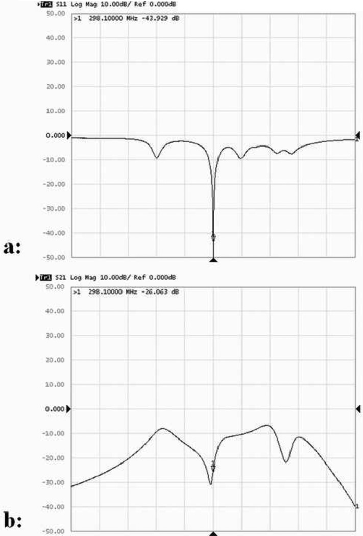
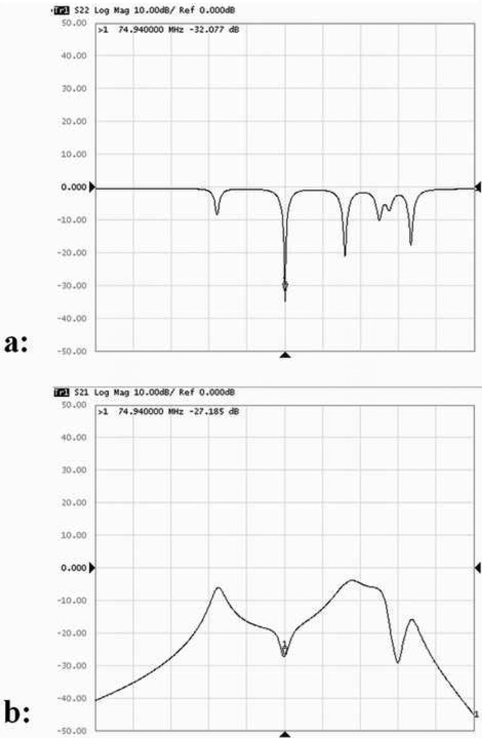
The resonance modes of one driving port of 1H channel and the isolation between the two driving ports were plotted in Fig.6. When 1H channel were tuned at 298.1 MHz, the reflection coefficient S11 of the two ports are both better than −43 dB, and the transmission coefficient S21 between the two quadurature ports is −26 dB. Fig.7 shows the resonance modes and the isolation between the two quadrature ports of the 13C channel when tuned at 74.94 MHz. The reflection coefficient S11 of the two ports are better than −32 dB, while the transmission coefficient S21 between the two quadurature ports is better than −27 dB. These results ensure excellent quadrature performance of both 1H and 13C channels.
Figure 7.
(a) S11 plot of one driving port of 1H channel showing the multimodal behavior of the dual-tuned volume coil with 8 1H elements; (b) S21 measurement of the two driving ports of 1H channel, indicating the accuracy of the 900 phase requirement of the two quadrature ports in the 300 MHz range.
The isolation between the 1H channel and the 13C channel is illustrated in Fig.8. The transmission coefficient S21 between two channels was plotted at both 74.94 MHz and 298.1 MHz with 30 MHz span. Also, the S21 from 50 MHz to 330 MHz span is shown. The S21 at 74.94 MHz is better than −50 dB and that at 298.1 MHz is better than −35 dB, indicating that the two channels of 1H and 13C are isolated sufficiently, which is essential for efficient acquisition of 13C MR signals.
Figure 8.
(a) S11 plot of one driving port of 13C channel, showing the well-defined resonance modes of the dual-tuned coil with 8 elements; (b) S21 measurement between the two quadrature driving ports of 13C channel. The sufficient isolation (~27dB) indicates accuracy of the 90° phase requirement of the two quadrature ports.
Based on the simulation results and bench tests, the capacitance Ct1 and Ct2 on the 1H element were 12.4 pF and 6.8 pF respectively. The capacitance Ct on the 13C element was 68 pF and a variable capacitor (Johneson9620, 0.5 – 2.5 pF) was parallel connected into the element to perform frequency tuning.
3.3 MRI tests
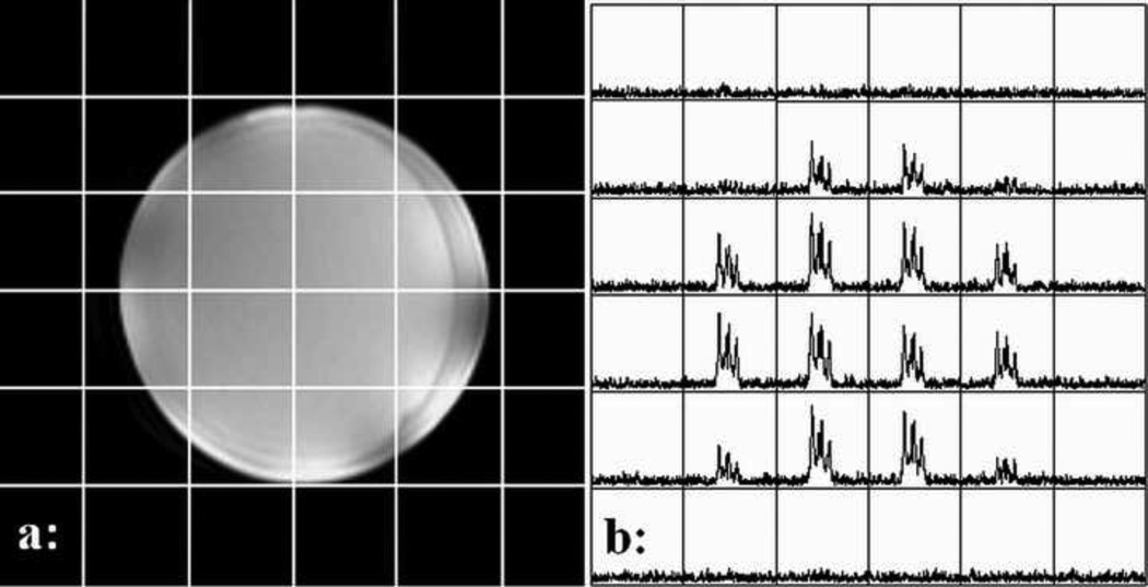
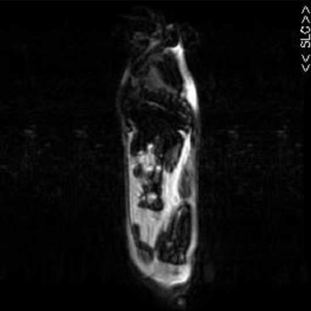
After B0 shimming using the 1H channel MR tests was performed. The 1H GRE image and 13C spectroscopic image in the axial plane of a corn oil phantom was acquired sequentially and are shown in Fig.9. These two images illustrate high quality of proton image and carbon spectroscopic image of the microstrip volume coil. The chemical shift artifacts of the oil phantom at the ultrahigh field of 7T are also clearly observed in this image. Another proton in vivo image of a mouse on sagittal plane shown is also shown in Fig.10. This demonstrates that the proposed dual-tuned volume coil design can provide a fairly homogeneous B1 field and image coverage with loading in the 300MHz range.
Figure 9.
S21 measurements between the 13C channel and the 1H channel (a) in frequency ranges of 50 – 330 MHz, (b) 75 MHz and (c) 298.1 MHz. Sufficient electromagnetic isolation between 13C channel and 1H channel of the proposed dual-tuned volume coil is essential for efficient acquisition of 13C signals.
Figure 10.
MR images of the dual-tuned microstrip volume coil at 7T: (a) 1H image of a corn oil phantom on axial plane (chemical shift artifacts of the oil phantom at the ultrahigh field of 7T are clearly observed in this image); (b) 13C FIDCSI spectroscopic image of the corn oil phantom (with natural abundance) on axial plane.
4. Discussion and Conclusion
A novel design for dual-tuned quadrature volume coil using a mix of capacitor terminated half-wavelength and quarter-wavelength microstrip resonators for multinuclear MR studies at 7T has been proposed. An example volume coil design for 1H/13C spectroscopic imaging for mouse study has been presented to demonstrate the feasibility of this method. High quality proton image and carbon spectroscopic image of a corn oil phantom have been obtained using this dual-tuned microstrip volume coil. Both simulations and MR experiment results have shown the excellent performance of the proposed design method.
In this design, mixed λ/2 and λ/4 resonators were utilized to fit the different resonant frequencies of 1H and 13C respectively. At the same length, λ/4 resonators operate at relatively low frequency compared with the commonly used λ/2 resonators in RF coil design. Therefore, the use of λ/4 resonators is advantageous for 13C channel and makes it much convenient to perform frequency tuning by using commercially available variable capacitors.
The FDTD simulation has shown that the dual-tuned microstrip volume coil can generate homogeneous B1 fields at both 1H and 13C resonant frequencies. When the elements of one frequency are excited there is nearly no signal in the elements of the other frequency, showing excellent isolation between the two channels, which is desired in dual-tuned RF coil designs because it can help to increase efficiency of heteronuclear MR signal excitation and detection. Quadrature driving has been applied to both the 1H and 13C channels of the volume coil to improve the SNR and reduce RF excitation power. The transmission parameters S21 between each pair of driving ports of 1H and 13C channels are −26 dB and −27 dB respectively, ensuring excellent quadrature performance of both 1H and 13C channels. Measured on a network analyzer, the transmission parameters S21 between a driving port of 1H and that of 13C is better than −50 dB at 75 MHz and −35 dB at 298.1 MHz. This measured result demonstrates that the 1H and 13C channels have been isolated excellently and is in agreement with the FDTD simulation results. In summary, this dual-tuned microstrip volume coil with mixed λ/2 and λ/4 resonant elements is feasible and efficient, provided that sufficient radial separation is maintained between the strip conductor and the ground to provide sufficient coupling between elements. The characteristic of the microstrip provides a simple approach to design dual-tuned volume coil for in vivo multinuclear MR at ultrahigh fields.
Figure 11.
1H in vivo image of a mouse on sagittal plane acquired using the 1H channel of the proposed dual-tuned volume coil at 7T. This preliminary 1H imaging result demonstrates that the proposed dual-tuned volume coil design can provide a fairly homogeneous B1 field and image coverage with loading in the 300MHz range.
Acknowledgments
This work was partially supported by NIH grants EB004453, EB008699 and EB007588-03S1, and a QB3 Research Award.
Footnotes
Publisher's Disclaimer: This is a PDF file of an unedited manuscript that has been accepted for publication. As a service to our customers we are providing this early version of the manuscript. The manuscript will undergo copyediting, typesetting, and review of the resulting proof before it is published in its final citable form. Please note that during the production process errors may be discovered which could affect the content, and all legal disclaimers that apply to the journal pertain.
References
- 1.de Graaf RA, Mason GF, Patel AB, Behar KL, Rothman DL. In vivo 1H-[13C]-NMR spectroscopy of cerebral metabolism. NMR Biomed. 2003;16(6–7):339–357. doi: 10.1002/nbm.847. [DOI] [PubMed] [Google Scholar]
- 2.Gruetter R, Adriany G, Choi IY, Henry PG, Lei H, Oz G. Localized in vivo 13C NMR spectroscopy of the brain. NMR Biomed. 2003;16(6–7):313–338. doi: 10.1002/nbm.841. [DOI] [PMC free article] [PubMed] [Google Scholar]
- 3.Henry PG, Tkac I, Gruetter R. 1H-localized broadband 13C NMR spectroscopy of the rat brain in vivo at 9.4 T. Magn Reson Med. 2003;50(4):684–692. doi: 10.1002/mrm.10601. [DOI] [PubMed] [Google Scholar]
- 4.Kurhanewicz J, Bok R, Nelson SJ, Vigneron DB. Current and potential applications of clinical 13C MR spectroscopy. J Nucl Med. 2008;49(3):341–344. doi: 10.2967/jnumed.107.045112. [DOI] [PMC free article] [PubMed] [Google Scholar]
- 5.Li S, Zhang Y, Wang S, Yang J, Ferraris Araneta M, Farris A, et al. In vivo 13C magnetic resonance spectroscopy of human brain on a clinical 3 T scanner using [2-13C]glucose infusion and low-power stochastic decoupling. Magn Reson Med. 2009;62(3):565–573. doi: 10.1002/mrm.22044. [DOI] [PMC free article] [PubMed] [Google Scholar]
- 6.Boada FE, Gillen JS, Shen GX, Chang SY, Thulborn KR. Fast three dimensional sodium imaging. Magn Reson Med. 1997;37(5):706–715. doi: 10.1002/mrm.1910370512. [DOI] [PubMed] [Google Scholar]
- 7.Thulborn KR, Davis D, Snyder J, Yonas H, Kassam A. Sodium MR imaging of acute and subacute stroke for assessment of tissue viability. Neuroimaging Clin N Am. 2005;15(3):639–653. xi–xii. doi: 10.1016/j.nic.2005.08.003. [DOI] [PubMed] [Google Scholar]
- 8.Constantinides CD, Kraitchman DL, O'Brien KO, Boada FE, Gillen J, Bottomley PA. Noninvasive quantification of total sodium concentrations in acute reperfused myocardial infarction using 23Na MRI. Magn Reson Med. 2001;46(6):1144–1151. doi: 10.1002/mrm.1311. [DOI] [PubMed] [Google Scholar]
- 9.Ugurbil K, Kingsley-Hickman PB, Sako EY, Zimmer S, Mohanakrishnan P, Robitaille PM, et al. 31P NMR studies of the kinetics and regulation of oxidative phosphorylation in the intact myocardium. Ann N Y Acad Sci. 1987;508:265–286. doi: 10.1111/j.1749-6632.1987.tb32910.x. [DOI] [PubMed] [Google Scholar]
- 10.Lei H, Zhu XH, Zhang XL, Ugurbil K, Chen W. In vivo 31P magnetic resonance spectroscopy of human brain at 7 T: an initial experience. Magn Reson Med. 2003;49(2):199–205. doi: 10.1002/mrm.10379. [DOI] [PubMed] [Google Scholar]
- 11.Hetherington HP, Kim JH, Pan JW, Spencer DD. 1H and 31P spectroscopic imaging of epilepsy: spectroscopic and histologic correlations. Epilepsia. 2004;45 Suppl 4:17–23. doi: 10.1111/j.0013-9580.2004.04004.x. [DOI] [PubMed] [Google Scholar]
- 12.Rothman DL, Shulman RG, Shulman GI. 31P nuclear magnetic resonance measurements of muscle glucose-6-phosphate. Evidence for reduced insulin-dependent muscle glucose transport or phosphorylation activity in non-insulin-dependent diabetes mellitus. J Clin Invest. 1992;89(4):1069–1075. doi: 10.1172/JCI115686. [DOI] [PMC free article] [PubMed] [Google Scholar]
- 13.Chew WM, Moseley ME, Nishimura MC, Hashimoto T, Pitts LH, James TL. A novel double-surface coil approach to phosphorus-31 spectroscopy: a study of hemispheric brain injury in the rat. Magn Reson Med. 1985;2(6):567–575. doi: 10.1002/mrm.1910020607. [DOI] [PubMed] [Google Scholar]
- 14.Shen GX, Boada FE, Thulborn KR. Dual-frequency, dual-quadrature, birdcage RF coil design with identical B1 pattern for sodium and proton imaging of the human brain at 1.5 T. Magn Reson Med. 1997;38(5):717–725. doi: 10.1002/mrm.1910380507. [DOI] [PubMed] [Google Scholar]
- 15.Shen GX, Wu JF, Boada FE, Thulborn KR. Experimentally verified, theoretical design of dual-tuned, low-pass birdcage radiofrequency resonators for magnetic resonance imaging and magnetic resonance spectroscopy of human brain at 3.0 Tesla. Magn Reson Med. 1999;41(2):268–275. doi: 10.1002/(sici)1522-2594(199902)41:2<268::aid-mrm9>3.0.co;2-g. [DOI] [PubMed] [Google Scholar]
- 16.Amari S, Ulug AM, Bornemann J, van Zijl PC, Barker PB. Multiple tuning of birdcage resonators. Magn Reson Med. 1997;37(2):243–251. doi: 10.1002/mrm.1910370217. [DOI] [PubMed] [Google Scholar]
- 17.Matson GB, Vermathen P, Hill TC. A practical double-tuned 1H/31P quadrature birdcage headcoil optimized for 31P operation. Magn Reson Med. 1999;42(1):173–182. doi: 10.1002/(sici)1522-2594(199907)42:1<173::aid-mrm23>3.0.co;2-o. [DOI] [PubMed] [Google Scholar]
- 18.Rath AR. Design and Performance of a Double-Tuned Bird-Cage Coil. Journal of Magnetic Resonance. 1990;86(3):488–495. [Google Scholar]
- 19.Vaughan JT, Hetherington HP, Otu JO, Pan JW, Pohost GM. High frequency volume coils for clinical NMR imaging and spectroscopy. Magn Reson Med. 1994;32(2):206–218. doi: 10.1002/mrm.1910320209. [DOI] [PubMed] [Google Scholar]
- 20.Zhang X, Zhu X, Qiao H, Liu H, Vaughan JT, Ugurbil K, et al. A circular-polarized double-tuned (31P and 1H) TEM coil for human head MRI/MRS at 7T. Toronto: 2003. p. 423. [Google Scholar]
- 21.Avdievich NI, Hetherington HP. 4 T Actively detuneable double-tuned 1H/31P head volume coil and four-channel 31P phased array for human brain spectroscopy. J Magn Reson. 2007;186(2):341–346. doi: 10.1016/j.jmr.2007.03.001. [DOI] [PMC free article] [PubMed] [Google Scholar]
- 22.Pang Y, Zhang X, Xie Z, Wang C, Vigneron D. Common-mode differential-mode (CMDM) method for double-nuclear MR signal excitation and reception at ultrahigh fields. IEEE Trans Med Imaging. 2011 Jun 20; doi: 10.1109/TMI.2011.2160192. Epub ahead of print. [DOI] [PMC free article] [PubMed] [Google Scholar]
- 23.Lee RF, Westgate CR, Weiss RG, Newman DC, Bottomley PA. Planar strip array (PSA) for MRI. Magn Reson Med. 2001;45(4):673–683. doi: 10.1002/mrm.1090. [DOI] [PMC free article] [PubMed] [Google Scholar]
- 24.Zhang X, Ugurbil K, Chen W. Microstrip RF surface coil design for extremely high-field MRI and spectroscopy. Magn Reson Med. 2001;46(3):443–450. doi: 10.1002/mrm.1212. [DOI] [PubMed] [Google Scholar]
- 25.Zhang X, Ugurbil K, Chen W. A microstrip transmission line volume coil for human head MR imaging at 4T. J Magn Reson. 2003;161(2):242–251. doi: 10.1016/s1090-7807(03)00004-1. [DOI] [PubMed] [Google Scholar]
- 26.Zhang X, Ugurbil K, Sainati R, Chen W. An inverted-microstrip resonator for human head proton MR imaging at 7 tesla. IEEE Trans Biomed Eng. 2005;52(3):495–504. doi: 10.1109/TBME.2004.842968. [DOI] [PubMed] [Google Scholar]
- 27.Zhang X, Zhu XH, Chen W. Higher-order harmonic transmission-line RF coil design for MR applications. Magn Reson Med. 2005;53(5):1234–1239. doi: 10.1002/mrm.20462. [DOI] [PubMed] [Google Scholar]
- 28.Pang Y, Xie Z, Li Y, Xu D, Vigneron D, Zhang X. Resonant mode reduction in radiofrequency volume coils for ultrahigh field magnetic resonance imaging. Materials. 2011;4(8):1333–1344. doi: 10.3390/ma4081333. [DOI] [PMC free article] [PubMed] [Google Scholar]
- 29.Wu B, Zhang X, Qu P, Shen GX. Design of an inductively decoupled microstrip array at 9.4 T. J Magn Reson. 2006;182(1):126–132. doi: 10.1016/j.jmr.2006.04.013. [DOI] [PubMed] [Google Scholar]
- 30.Wu B, Zhang X, Qu P, Shen GX. Capacitively decoupled tunable loop microstrip (TLM) array at 7 T. Magn Reson Imaging. 2007;25(3):418–424. doi: 10.1016/j.mri.2006.09.031. [DOI] [PubMed] [Google Scholar]
- 31.Adriany G, Van de Moortele PF, Wiesinger F, Moeller S, Strupp JP, Andersen P, et al. Transmit and receive transmission line arrays for 7 Tesla parallel imaging. Magn Reson Med. 2005;53(2):434–445. doi: 10.1002/mrm.20321. [DOI] [PubMed] [Google Scholar]
- 32.Wu B, Wang C, Kelley DA, Xu D, Vigneron DB, Nelson SJ, et al. Shielded microstrip array for 7T human MR imaging. IEEE Trans Med Imaging. 2010;29(1):179–184. doi: 10.1109/TMI.2009.2033597. [DOI] [PMC free article] [PubMed] [Google Scholar]
- 33.Wu B, Wang C, Krug R, Kelley DA, Xu D, Pang Y, et al. 7T human spine imaging arrays with adjustable inductive decoupling. IEEE Trans Biomed Eng. 2010;57(2):397–403. doi: 10.1109/TBME.2009.2030170. [DOI] [PMC free article] [PubMed] [Google Scholar]
- 34.Adriany G, Auerbach EJ, Snyder CJ, Gozubuyuk A, Moeller S, Ritter J, et al. A 32-channel lattice transmission line array for parallel transmit and receive MRI at 7 tesla. Magn Reson Med. 2010;63(6):1478–1485. doi: 10.1002/mrm.22413. [DOI] [PMC free article] [PubMed] [Google Scholar]
- 35.Metzger GJ, van de Moortele PF, Akgun C, Snyder CJ, Moeller S, Strupp J, et al. Performance of external and internal coil configurations for prostate investigations at 7 T. Magn Reson Med. 2010;64(6):1625–1639. doi: 10.1002/mrm.22552. [DOI] [PMC free article] [PubMed] [Google Scholar]
- 36.Xie Z, Xu D, Kelley D, Vigneron D, Zhang X. A dual-tuned quadrature microstrip volume coil for 13C/1H MRI/S at 7T. Toronto: 2008. p. 1113. [Google Scholar]


