Abstract
The traction force produced by biological cells has been visualized as distortions in flexible substrata. We have utilized quantitative phase microscopy by digital holography (DH-QPM) to study the wrinkling of a silicone rubber film by motile fibroblasts. Surface deformation and the cellular traction force have been measured from phase profiles in a direct and straightforward manner. DH-QPM is shown to provide highly efficient and versatile means for quantitatively analyzing cellular motility.
OCIS codes: (090.1995) Digital holography, (170.0180) Microscopy, (170.3880) Medical and biological imaging
1. Introduction
Cell-substrate interactions play a crucial role in the migratory behavior of adhesive cells. A cell must exert a propulsive force to overcome friction and move along a surface. Accurate measurements of the magnitude and direction of traction forces are needed to understand cell movement. These forces are known to be able to deform a flexible substrate. Knowledge of substrate elasticity, for example stiffness, and optical measurement of substrate distortion can be combined to produce estimates of the traction forces of cells.
These forces were first visualized by Harris et al. as wrinkles in a thin cross-linked silicone rubber film [1]. Time-lapse movies of substrate distortion indicated that cells exerted traction as a shearing force in the plane of the plasma membrane surface closest to the substrate. The stiffness of the silicone substrate, measured with a glass micro-needle, was ~0.001 dyn/μm, and the traction force generated by embryonic chick fibroblasts was ~20 × 10−3 dyn/cell. The lateral displacement of a non-wrinkling substrate surface has been visualized by embedding microspheres in the substrate [2,3]. The maximum traction force of fast-moving keratocytes was 2.5–4.5 × 10⁻³ dyn/cell. A non-wrinkling silicone rubber surface is prepared by allowing the film to become welded to the sides of a vessel. On a wrinkling surface, the wrinkles of keratocytes are parallel to the direction of cell movement, whereas for fibroblasts they are perpendicular. The use of polyacrylamide as the substrate with embedded microspheres allows non-wrinkle elastic deformation with a significantly larger range of stress [4]. Lo et al. have used this technique to study effects of substrate rigidity on cell movement [5]. Traction force measurements on single cells have been made using various methods. For example, a calibrated microneedle load was placed in the path of locomoting cells [6]. Polymorphonuclear leukocytes have been enticed into a micropipette filled with chemoattractant [7], and by applying a known hydrostatic pressure to the pipette, a force of ~3 × 10⁻³ dyn was just sufficient to stop leukocyte locomotion.
The mechanical properties of a substrate can be characterized by atomic force microscopy [8] or hydrostatic pressure applied by a micropipette [9]. Wrinkling is usually visualized by bright field or DIC microscopy. These approaches, however, do not directly yield quantitative measures of deformation. Here, digital holographic microscopy (DHM) has been used to visualize wrinkle formation, extract quantitative measures of surface deformation and estimate the cellular traction force in a direct and straightforward manner.
Digital holography is an emerging technology of a new paradigm in general imaging and biomedical applications [10]. Quantitative phase microscopy (QPM) is a particularly important feature of DHM [11,12], because it allows measurement of optical thickness with nanometer-scale accuracy by single-shot, wide-field acquisition, and it yields phase profiles without some of the complications of other phase imaging methods. The phase image is immediately and directly available on calculating the 2-dimensional complex array of the holographic image, and the phase profile conveys quantitative information about the physical thickness and index of refraction of cells and the substrate.
2. Materials and methods
2.1. DHM setup
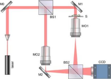
The DHM setup used in this work is illustrated in Fig. 1 . It consists of a Mach-Zehnder interferometer illuminated with a HeNe laser [10]. The object arm contained a sample stage and a microscope objective lens (MO1) that projected a magnified image of the object onto a CCD camera. The reference arm similarly contained MO2, so that the holographic interference pattern contained fringes due to interference between the diffracted object field and the off-axis reference field. The numerical aperture (NA) of the microscope objectives is 0.25 and the magnification is 10×. The specification of CCD is 1024 × 768, and the pixel size is 4.65μm. The QPM images were reconstructed from the captured holograms by the angular spectrum method [10]. Aberrations and background distortions of the optical field were minimized by available DHM techniques [10]. LED illumination from above BS1 provided a means of acquiring a bright-field (non-interferometric) microscopy image of the specimen.
Fig. 1.

DHM setup. M’s: mirrors; BS’s: beam splitters; MO’s: microscope objectives; S: sample object
2.2. Cells-substratum samples
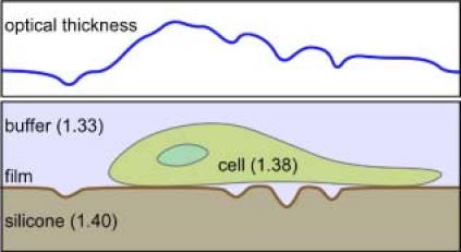
The sample consisted of fibroblast cells cultured on a thin layer of silicone rubber, Fig. 2 . The silicone rubber film was prepared as described previously [1,13]. An approximately 100 μm-thick layer of silicone fluid was spread onto the surface of a Petri dish. Exposure to heat for 1-2s resulted in the formation of ~1 μm thick skin of cross-linked material on top of a lubricant layer of silicone oil on the Petri dish. Normal human dermal fibroblasts(NHDF), maintained at a sub-confluent density in fibroblast basal medium with fibroblast growth medium and passaged every 72–96 h, were rinsed with Hanks’ balanced salt solution, released from the substrate by treatment with 0.25% (w/v) trypsin in 2.21 mM ethylenediaminetetraacetic acid, centrifuged and re-suspended in growth medium. Silicone substrates were sterilized with 70% ethanol and rinsed with sterile phosphate buffered saline prior to cell seeding. Approximately 104 cells were seeded onto a Petri dish prepared as described above, culture medium was added, and the Petri dish was covered and incubated at 37 °C and 5% CO2. The culture medium was changed every 48 h.
Fig. 2.

Schematic of the cell-substrate sample (lower) and the corresponding optical thickness profile (upper).
3. Results and discussions
3.1. DHM analysis
Figure 3 illustrates DHM analysis of fibroblasts wrinkling a silicone rubber film. Interference of the diffracted object field and off-axis reference field resulted in the hologram, Fig. 3a). In Fig. 3b), the angular spectrum shows the zero order and a pair of first order components. One of the first-order components was separated with a numerical band-pass filter when the off-axis angle of the reference beam was properly adjusted. The corresponding amplitude and the phase profiles after correct centering of the filtered angular spectrum and numerical propagation to the object focus distance are shown in Fig. 3c) and Fig. 3d). For comparison, Fig. 3e) shows the bright field image for LED illumination, slightly defocused to make the transparent structures visible.
Fig. 3.

DHM analysis of fibroblasts wrinkling the silicone rubber film. The field of view is 190 × 176 μm2 with 800 × 742 pixels. a) Hologram; b) Angular spectrum; c) Amplitude image; d) Quantitative phase image; e) Bright field image.
3.2. Multi-mode imaging of cells wrinkling the silicone rubber
In DHM, a single hologram can be used to generate images that emulate several different optical microscopy techniques [14]. Fourier transformation and the angular spectrum methods [10] were applied to the complex hologram obtained in Fig. 3 to calculate the phase-contrast, dark-field, Zernike and differential interference contrast (DIC) images. Multi-mode images of fibroblasts wrinkling the silicone rubber are displayed in Fig. 4 . All were generated from the same hologram, Fig. 3a). During numerical reconstruction of the image, zero order and twin-image terms of the angular spectrum were suppressed. In the dark-field image Fig. 4a), a numerical filter of the form was used to suppress the zero-order background from the image, where and are the spatial frequencies. The resulting intensity image is proportional to , where φ is the phase profile of the object, minus the overall average phase value. Some structural information is lost in this process since it cannot distinguish from . If the filter is changed to , then the intensity image is proportional to , which is the positive Zernike phase contrast image Fig. 4b). The negative Zernike phase contrast image Fig. 4c), has reversed polarity by using the filter . The DIC filter is , where and are the lateral shears. Images reconstructed from the filtered and unfiltered spectra were then combined, and Fig. 4d) was extracted as . Finally, the spiral DIC image Fig. 4e) was generated with the filter , where θ is the polar angle in the frequency domain. The final image corresponds to the convolution of the original with , where r and are the radius and polar angle in real space. The spiral DIC is very sensitive to phase jumps, such as at edges [10].
Fig. 4.

Multimode imaging from a single hologram. The field of view is 190 × 176 μm2 with 800 × 742 pixels. a) dark field; b) Zernike+; c) Zernike–; d) DIC; e) spiral DIC.
3.3. Examples of results
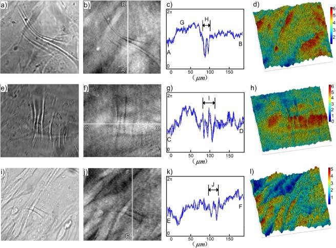
Examples of fibroblasts wrinkling the silicone rubber film are presented in Fig. 5 . Figure 5a) shows a bright-field image, Fig. 5b) a quantitative phase image by DH-QPM, Fig. 5c) the optical thickness profile corresponding to the highlighted vertical line in Fig. 5b), and Fig. 5d) a pseudo-color pseudo-3D rendering of the phase image in Fig. 5b). Two other examples are shown in Fig. 5e) through h) and Fig. 5i) through l). In all cases, the field of view was 190 × 176 μm2 with 800 × 742 pixels. The cells were cultured on the substrate for 24–48 h prior to image acquisition. (For brevity, most of the following descriptions refer to the first example.) The bright-field image in Fig. 5a) shows several fibroblasts and a few prominent wrinkles. In the QPM image in Fig. 5b), the full range of the gray scale values, from black to white, covers the phase variation 0–2π. The cell bodies appear as bright oblong areas because of the higher average refractive index of cytoplasm (~1.38) than buffer (1.33). The wrinkles, by contrast, appear as conspicuous dark lines, indicating that the wrinkles folded into, not out of, the underlying silicone oil layer (1.40). This situation, depicted in Fig. 2, is consistent with the established view [1]. The wrinkles were in general perpendicular to the cell body and the direction of cell motion, as expected for this cell type. The graph in Fig. 5c) is a profile of phase variation along the line AB of Fig. 5b). In fact it plots profiles along ten adjacent vertical lines, to indicate the general noise level. Most of the ‘fluctuations’ appear to be non-random between adjacent lines, and the noise level is seen to be less than 0.1 radian. The pseudo-3D rendering in Fig. 5d) can provide intuitive visualization of the cells and wrinkling, although one has to use caution interpreting such pictures because the optical thickness represents the combined effect of the physical thickness and the refractive index. For example, the upward bump at G is due to the presence of a cell body (average index 1.38) immersed in buffer solution (1.33). For the phase difference a 1.0 radian phase jump in this case corresponds to physical thickness of the cell. On the other hand, for the wrinkles in area H, the relevant index difference is, and the physical depth of the wrinkle is.
Fig. 5.

Examples of cells wrinkling a silicone rubber film. The field of view was 190 × 176 μm2 with 800 × 742 pixels. a), e) and i) Bright field images; b), f) and j) Quantitative phase images; c), g) and k) Cross-sections of phase profiles along highlighted lines AB in b), CD in f) and EF in j); d), h) and l) Pseudo-color 3-D rendering of phase images b), f) and j).
3.4. Phase movie of fibroblasts wrinkling the silicone rubber film
A time-lapse phase movie of the migration of cells was recorded every 3 min over a period of 2 hours. We focused on individual cells without neighbors in the field of view to minimize the effects of intercellular mechanical interactions through the elastic substrate. In Fig. 6 , an individual cell is seen to spread and crawl on the silicone rubber surface, changing its shape and orientation. The overall area of the cell increased as it formed protrusions at the leading edge. The traction force compressed the silicone rubber film and stretched it, forming prominent wrinkles in the surrounding area (see arrow in the last image). This time-lapse sequence of substrate distortion also indicated that the wrinkles are in general perpendicular to the cell body and the direction of cell motion, as expected.
Fig. 6.

An excerpt of several frames from phase movie recordings of cells wrinkling a silicone rubber film (Media 1 (25.5MB, MOV) ). The field of view was 190 × 176 μm2 with 800 × 742 pixels. Time interval of two contiguous images above was around 30 min.
3.5. Force estimation
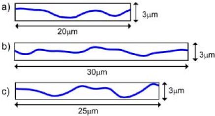
The phase information of the cells wrinkling the silicone rubber film enabled estimation of traction forces exerted according to the degree of wrinkling the cells produced. Figure 7a ) shows the average phase profile of 10 adjacent lines of the wrinkled area H of Fig. 5c). The amount of horizontal deformation was then taken as the difference between the total length of the graph (numerically calculated to be 24.11 μm) and the horizontal distance (20.0 μm) of Fig. 7a), that is, 4.11 μm. Using the stiffness of the silicone rubber 0.001 dyn/μm measured with glass needles in Ref. [1], the traction force exerted by this cell was then estimated as. Similar analysis on the wrinkle area I of Fig. 5g) and J of Fig. 5k) yielded horizontal deformations of and , and almost identical traction force.
Fig. 7.

Phase profiles scaled as physical thickness and plotted in proportion to horizontal distance. a) Wrinkled area H from Fig. 5c). b) Wrinkled area I from Fig. 5g). c) Wrinkled area J from Fig. 3k). In each case, the average of 10 adjacent profiles is presented.
To the best of our knowledge, this is the first quantitative profiling of substrate deformation and wrinkling under cellular traction force achieved by the quantitative phase microscopy of digital holography. Our measured traction force for NHDFs is a factor of five smaller than for chick heart fibroblast of Ref. [1]. The force will vary with the cell type, the physiological state of the cells, substrate and buffer preparation, etc.
Some issues and possible improvements of the technique are worth mentioning. There is an inherent difficulty in attempting to measure the horizontal traction force from vertical wrinkle deformations. Wrinkling is thought to be more elastic than plastic, so that the wrinkles disappear on detachment of cells from the substrate and a flat surface is restored [1]. One suspects, however, that substrate elasticity will be incomplete and deformation not entirely linear. A non-wrinkling substrate together with embedded microspheres could enable direct measurement of elastic horizontal deformations, albeit at discrete locations [4]. Another possible complication is the overlap of the cell body and intra- and extra-cellular particulate matter in the middle of a wrinkle, which would invalidate the phase difference calculation. One must therefore make judicious choices of location for valid implementation of the force measurement procedure outlined above.
4. Conclusions
The traction forces exerted by fibroblasts cultured on a silicone rubber substratum have been visualized as an elastic distortion and wrinkling by DH-QPM. The traction force has been measured as ~4 × 10⁻³ dyn/cell based on the degree of wrinkling determined from phase information. The basic principles of DH have been applied to quantitative imaging of wrinkles on silicone rubber due to cell adhesion and motility. The approach is sensitive to cellular forces and it can detect and quantify variations in force within the adhesion area of a cell over time. DH-QPM is shown to be an effective approach for measuring the traction forces of cells.
Acknowledgments
We thank Professor Albert Harris for advice on the preparation of silicone rubber substrata and cell culture. This work was supported in part by the National Science Foundation under grant No. 0755705.
References and links
- 1.Harris A. K., Wild P., Stopak D., “Silicone rubber substrata: a new wrinkle in the study of cell locomotion,” Science 208(4440), 177–179 (1980). 10.1126/science.6987736 [DOI] [PubMed] [Google Scholar]
- 2.Lee J., Leonard M., Oliver T., Ishihara A., Jacobson K., “Traction forces generated by locomoting keratocytes,” J. Cell Biol. 127(6), 1957–1964 (1994). 10.1083/jcb.127.6.1957 [DOI] [PMC free article] [PubMed] [Google Scholar]
- 3.Oliver T., Jacobson K., Dembo M., “Traction forces in locomoting cells,” Cell Motil. Cytoskeleton 31(3), 225–240 (1995). 10.1002/cm.970310306 [DOI] [PubMed] [Google Scholar]
- 4.Dembo M., Wang Y. L., “Stresses at the cell-to-substrate interface during locomotion of fibroblasts,” Biophys. J. 76(4), 2307–2316 (1999). 10.1016/S0006-3495(99)77386-8 [DOI] [PMC free article] [PubMed] [Google Scholar]
- 5.Lo C. M., Wang H. B., Dembo M., Wang Y. L., “Cell movement is guided by the rigidity of the substrate,” Biophys. J. 79(1), 144–152 (2000). 10.1016/S0006-3495(00)76279-5 [DOI] [PMC free article] [PubMed] [Google Scholar]
- 6.Oliver T., Lee J., Jacobson K., “Forces exerted by locomoting cells,” Semin. Cell Biol. 5(3), 139–147 (1994). 10.1006/scel.1994.1018 [DOI] [PubMed] [Google Scholar]
- 7.Usami S., Wung S. L., Skierczynski B. A., Skalak R., Chien S., “Locomotion forces generated by a polymorphonuclear leukocyte,” Biophys. J. 63(6), 1663–1666 (1992). 10.1016/S0006-3495(92)81745-9 [DOI] [PMC free article] [PubMed] [Google Scholar]
- 8.Dimitriadis E. K., Horkay F., Maresca J., Kachar B., Chadwick R. S., “Determination of elastic moduli of thin layers of soft material using the atomic force microscope,” Biophys. J. 82(5), 2798–2810 (2002). 10.1016/S0006-3495(02)75620-8 [DOI] [PMC free article] [PubMed] [Google Scholar]
- 9.Lin D. C., Yurke B., Langrana N. A., “Use of rigid spherical inclusions in Young’s moduli determination: application to DNA-crosslinked gels,” J. Biomech. Eng. 127(4), 571–579 (2005). 10.1115/1.1933981 [DOI] [PubMed] [Google Scholar]
- 10.Kim M. K., “Principles and techniques of digital holographic microscopy,” SPIE Rev. 1, 1–50 (2010). [Google Scholar]
- 11.Cuche E., Bevilacqua F., Depeursinge C., “Digital holography for quantitative phase-contrast imaging,” Opt. Lett. 24(5), 291–293 (1999). 10.1364/OL.24.000291 [DOI] [PubMed] [Google Scholar]
- 12.Mann C. J., Yu L. F., Lo C. M., Kim M. K., “High-resolution quantitative phase-contrast microscopy by digital holography,” Opt. Express 13(22), 8693–8698 (2005). 10.1364/OPEX.13.008693 [DOI] [PubMed] [Google Scholar]
- 13.A. K. Harris, University of North Carolina at Chapel Hill, (personal communication).
- 14.Liu C., Bae Y. S., Yang W. Z., Kim D. Y., “All-in-one multifunctional optical microscope with a single holographic measurement,” Opt. Eng. 47(8), 087001 (2008). 10.1117/1.2968708 [DOI] [Google Scholar]


