Abstract
Brain tumors are the most feared complications of cancer. Their treatment is challenging due to the lack of good imaging modality and the inability to remove the complete tumor. Facilitating tumor removal by accessing regions outside the “line-of-sight” will require a highly dexterous and MRI compatible robot. We present our work towards the development of a MRI-compatible neurosurgical robot. We used two antagonistic shape memory alloy (SMA) wires as actuators for each joint. Due to the size limitation of the device, we rely on temperature feedback to control the joint motion of the robot. We have developed a theoretical model based on Tanaka’s model to characterize the joint motion with the change in SMA wire temperature. The results demonstrated that the SMA wire temperature can be used reliably to predict the motion of the robot. We then used a PWM scheme and switching circuit to control the temperature of multiple SMA wires. Experimental results showed that we can actuate the robot reliably and observe joint motion in a gelatin medium. MR images also showed that the robot is fully MRI-compatible and creates no significant image distortion.
Index Terms: Meso-scale robot, Shape Memory Alloy, MRI-compatible robot, Neurosurgery
I. Introduction
Brain tumor occurs in 20-40% of adult cancer patients and despite numerous advances in treatment, the prognosis for these patients is poor with a median survival of 4-8 months [1]. Currently, the optimal treatment for most brain tumors involves primary surgical resection to remove as much tumor as possible. However, due to the lack of good continuous imaging modality for intraoperative intracranial procedures, it is extremely challenging for surgeons to remove brain tumors completely with traditional surgical devices. The ability of intraoperative magnetic resonance imaging (MRI) to provide excellent soft-tissue contrast can supplement the surgeon’s capabilities, resulting in less trauma to surrounding healthy brain tissue during surgery. To minimize the trauma to surrounding healthy brain tissue, it would be beneficial to operate through a narrow surgical corridor (maximum 12.5mm in diameter) dissected by the neurosurgeon. Due to the above mentioned requirements, a highly dexterous, small cross-section, and MRI-compatible robot is proposed to overcome these challenges.
Several MRI-compatible and surgical robots have been developed by the research community. Masamune et al. [2] and Chinzei et al. have developed MRI-guided needle insertion robots [3]. Webster et al. built a snake-like miniature flexible active cannula that derives bending actuation [4]. Degani et al. developed a Highly Articulated Robotic Probe (HARP) that can exploit its snake-like structure to navigate in a confined anatomical environment while minimally interacting with the environment along its path [5]. Xu and Simaan presented a multiple-backbone continuum robot which can be potentially used for minimal invasive surgery [6]. These kinds of snake-like or continuum robots have a limitation that they can only be bent to a continuous curve which limits its application especially in a space constrained environment. Besides, although these robots themselves are small, the actuation mechanisms behind the robots are relatively large. This also limits the portability of the robots and makes the use of these robots in MRI room challenging. Wang et al. built a MRI compatible neural interventional robot using a piezoelectric actuator system [7]. The robot is MRI compatible, but it has only one degree of freedom and cannot be used to reach the target which is not in the “line-of-sight”.
SMA has a special ability to memorize its shape at a lower temperature and recover large deformation on thermal activation. When a SMA wire is at a lower temperature, it can be bent or stretched and it will hold the shape until heated above the transition temperature. Upon heating, the SMA wire recovers its original (memorized) shape. This is called Shape Memory Effect (SME). SME is caused by a transformation from martensite phase to austenite phase in the material as shown schematically in Fig. 1. This phenomenon can be traced to the lattice structure and the associated deformation mechanisms inside the material. The most common shape memory material is an alloy of nickel and titanium called Nitinol (Nickel Titanium alloy developed at the Naval Ordinance Lab), which was discovered by Gilfrich, Buehler and Wiley [8]. The recoverable strain of Nitinol is up to a maximum of about 8% [9] and it can generate extremely large forces during phase transformation due to its three to four fold increase in Young’s modulus in austenite phase compared to martensite phase [10]. This phenomenon provides a good mechanism for actuation. In neurosurgical application, since electrocauterization of the tumor (through the electrocautery probes located on the robot end-effector [11]) will enable removal of tissue, it may not be necessary for the robot to exert a large force to move the tissue. However, it is advantageous to be able to generate the required force at the end-effector through SMA actuation of the distal links to move the tumor, if necessary, during electrocautery.
Fig. 1.
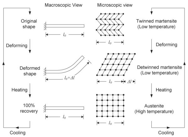
Shape Memory Effect of Bending.
To use SMA as actuators, it is important to first characterize it. Shaw and Churchill et al. [12], [13] have published a series of papers to introduce uninitiated engineers to the testing of SMA. They described special experimental techniques that help to illuminate and quantify the macroscopic thermomechanical behavior. Although many previous works have been done in the area of SMA characterization [12]–[15], the testing of SMA is not yet standardized and material property tables are either not available or provide incompletely. This is because SMA behavior is inherently nonlinear, hysteretic, and extremely temperature dependent. Since each SMA is different, it is necessary for us to develop our own experimental setup to obtain a satisfactory physics-based characterization of the material. Besides, most published research is based on uniaxial tensile tests. However, for our application, bending (to enable revolute joint motion) is the most important behaviour which we are interested in characterizing and hence it is one of the primary focus of this paper.
PWM has been shown to be the most effective method regarding the control of SMA actuators. It was shown in [16] that the SMA actuator consumed 30% less energy when controlled by a PWM controller than controlled by continuous PD controllers while maintaining the same positioning accuracy. Price et al. [17] used a microprocessor which had three available PWM channels to control SMA actuators. Bundhoo et al. [18], [19] used a microcontroller-based PWM-PD controller to control the finger in emulating natural joint motions. In most literature, however, a PWM signal can only be used to control one SMA wire. Thus, we propose to use PWM and a switching circuit to control multiple SMA wires simultaneously and independently by using only one power supply.
In our previous work [11], a preliminary prototype of a Minimally Invasive Neurosurgical Intracranial Robot (MINIR) using SMA wires as actuators was developed. It was shown that brass and SMA are MRI-compatible. In [20] and [21], we discussed a new design of MINIR which improves several limitations of the previous prototype. In this paper, we present additional results on testing the robot inside MRI to show that MINIR is fully MRI-compatible. Besides, we also computed the SNR values of a series of dynamic MR images to show that actuating the robot inside MRI did not cause significant noise in the MR images.
In this paper, we discuss the detailed design features of the robot in section II and present the design of our experimental setup which is used to characterize the SMA in section III. Section IV describes the correlation between bending displacement (rotation of the joint) and the SMA temperature. Section V describes the implementation of the PWM controller and the switching circuit. In section VI, we show the results of our SMA wire characterization experiment as well as controlling the temperature of multiple SMA wires (and hence the joint angle) by using only one power supply. We also prove that the 3-DOF robot is able to move in a gelatin medium and it is fully MRI-compatible by showing the results from our testing in MRI. Finally, in section VII, we make some concluding remarks.
II. Robot Design
The current design of MINIR is shown in Fig. 2. The robot consists of nine revolute joints and the joints are actuated by 0.5mm diameter SMA wires. The two probe tips shown in the figure is the envisioned system for electrocauterizing the tumor. The hollow core design of the robot allows for the passage of electrical wiring that can be used to actuate individual SMA actuators, to transfer signals of sensors as well as for the electrocautery wires to reach the two probe tips on the top. The hollow cross-section area of the body segment (Fig. 2(b)) is 50.27mm2, and the total cross-section area of the two columns and two SMA wires is 17.01mm2. There is still 33.26mm2 (66%) left for other wires and tubes to go through. Since brass has been proven to be MRI-compatible and creates no significant distortion on MR images [11], we chose brass to fabricate this prototype (see Fig. 3). In our current prototype presented in this paper, we have not developed the bipolar electrocautery system, since our primary goal was to characterize SMA actuation and control joint motion using PWM.
Fig. 2.
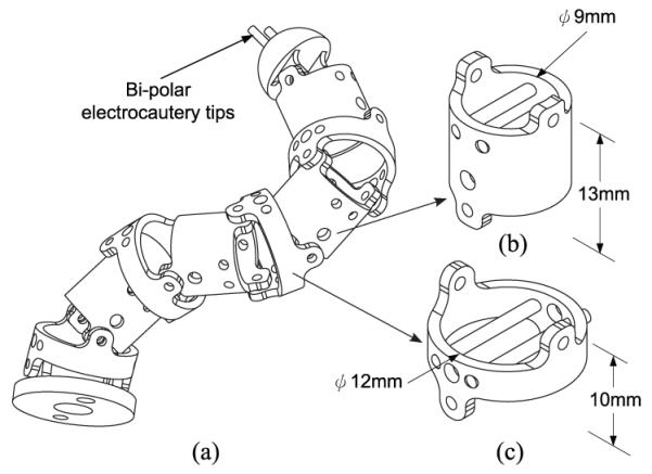
(a) Envisioned MINIR schematic, (b) Body segment of the prototype and (c) Ring segment of the prototype.
Fig. 3.
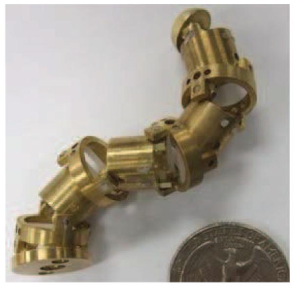
Brass prototype of MINIR.
In current prototype of MINIR, all joints were put on the outside surface of the robot to keep the center of the robot hollow [20]. Thus, all the wiring and tubes can be put inside the robot. This design makes the robot more compact and easier to shield. The two major links of MINIR are shown schematically in Fig. 2(b)(c). The larger holes of the links were milled to allow for the passage of the SMA wires, and the remaining smaller holes are for columns to go through. These columns are used for SMA actuators to push against and transmit the necessary actuation force to each joint resulting in joint motion. MINIR has totally nine revolute joints and the motion range of each joint is ±30°. The workspace of MINIR is shown as Fig. 4, and the motion range of the tip is 120mm along x and y axes, and 80mm along the z-axis. The origin (0, 0, 0) in Fig. 4 is the center of the bottom link of the robot.
Fig. 4.
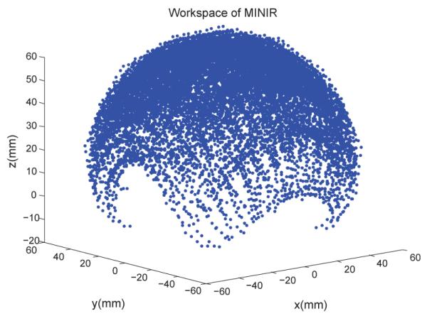
The workspace of MINIR.
Fig. 5 shows how this actuation mechanism works. In the stationary condition (Fig. 5(a)), SMA wires were bent to the desired shape to keep the links straight. To move the link clockwise, the left side SMA wire need to be actuated and it recovers its original memorized straight shape. As a result, the body segment will be pushed by the wire and cause a clockwise rotation as shown in Fig. 5(b). We used two antagonistic SMA wires for each joint, so that each joint could be moved back and forth individually. These two new design features (with respect to our previous prototype [11]) not only greatly increases the joint range of motion with independent joint actuation capability but also enables us to route wires and tubes for soft-tissue irrigation and electrocautery hardware through the center of the robot [21].
Fig. 5.
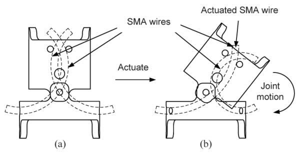
Actuation mechanism: (a) Stationary (b) Actuated.
III. SMA Characterization
The thermomechanical properties of SMA depend on many variables, such as manufacturing process, dimension, pre-strain, stress level, temperature, annealing condition and thermomechanical history. This section focuses on the experimental setup to characterize SMA response to temperature. We would like to correlate the bending displacement of a robot link with the temperature of the SMA wire so that we can use temperature as a feedback signal to control the motion of each joint as well as the end-effector position of the robot. The goal of this experiment was to develop a systematic test especially for MINIR and to collect sufficient data to estimate the performance of MINIR. Furthermore, it can also be used to determine important material parameters of SMA that are required for the analytical model.
A. Apparatus design
For the experimental apparatus design, we followed the suggestions of ASTM standard F2082-03. This standard is used for determination of transformation temperatures (TTRs) of SMA, however, it can be extended to perform the tests of strain-temperature relation and force-temperature relation by adding a force sensor. The apparatus design is shown as Fig. 6. For our robot, the SMA actuators were distributed antagonistically. Thus, the apparatus design should have similar configuration as the robot joint and be capable of testing two SMA wires at the same time. As a result, there are two pins, which act as the two columns in Fig. 2(b)(c), on the extension plate. There are also two larger columns (SMA fixer) on the main frame which were used to pinch/grasp the SMA wires.
Fig. 6.
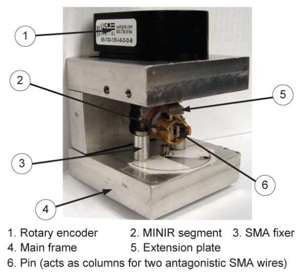
SMA characterization apparatus.
The apparatus also consists of a rotary encoder with a resolution up to 2880 pulses per revolution. For temperature sensing, we used T-type thermocouples along with a thermally conductive paste to attach the thermocouples to the SMA wires. Thermally conductive paste has high thermal conductivity and high resistance, which is used to ensure heat transfer while preventing current flowing through thermocouples. The data acquisition system has sixteen 16-bits A/D converters with 15kHz sampling rate. The resolution of a ±5V input signal is 0.076mV for a 16-bits A/D converter, however, a 0.076mV variation in voltage measurement is too small to precisely measured and it leads to about 1.8°C variation in the temperature estimate. As a result, signal amplifiers were necessary to amplify the readings of thermocouples for our system. We used Linear Technology LT1920 precision instrumentation amplifiers to implement the amplification circuit.
B. SMA modeling
To precisely control the motion of MINIR using temperature feedback, a theoretical model to describe the correlation between bending displacement and temperature of SMA wires was necessary. This section describes the details of the model and outlines the necessary parameters for this model. We have used a widely used constitutive model, namely, Tanaka’s model [22], to describe the material behavior of the one-way shape memory effect. In this model, only uniaxial loading behavior is considered and quasistatic deformation is assumed, resulting in an isothermal condition. It is also assumed that strain, temperature and the martensite volume fraction are the only state variables. Most of the constitutive models are developed for quasistatic loading and it is assumed that the material at each instant is in thermodynamic equilibrium.
According to [22]–[24], the constitutive equation of SMA is a function of stress (σ), temperature (T), martensite volume fraction (ζ) and strain (ε). The general form can be written as:
| (1) |
where E(ε, ζ, T) represents the Young’s modulus of material, Ω(ε, ζ, T) is the phase transformation coefficient and (Θ(ε, ζ, T) is the thermal expansion coefficient of SMA. Tanaka [22] developed an exponential expression to describe the martensite volume fraction as a function of stress and temperature. Liang and Rogers [23] presented a model which is based on the rate form of the constitutive equation developed by Tanaka. The difference between these two models is in the modeling of the martensite volume fraction. A major limitation of Tanaka’s and Liang and Roger’s models is that they do not capture the stress-induced detwinning of the martensite phase. Brinson [24] divided martensite volume fraction into two parts, namely stress-induced and temperature-induced components, and modified Tanaka’s model accordingly. We will discuss Tanaka’s model [22] and explain how to fully define the parameters of the SMA constitutive model through experiments. In this model, the strain, temperature, and martensite volume fraction are assumed to be independent state variables. Thus, the constitutive equation is given by:
| (2) |
where (ε0, σ0, ζ0, T0) are the initial conditions of SMA. This equation shows that the stress consists of three parts: mechanical stress, stress due to phase transformation and thermal expansion stress. For a specific material, Ω is a constant and can be expressed as:
| (3) |
where εL is the maximum recoverable strain of SMA. Eq. (3) implies that the phase transformation coefficient is a function of martensite volume fraction because the Young’s modulus is a function of martensite volume fraction. The effective Young’s modulus of the material containing both austenite and martensite phases, results in the expression:
| (4) |
where EA and EM are the Young’s moduli of austenite phase and martensite phase respectively. The ratio of EA to EM is generally larger than two, which enables us to use the antagonistic setup of SMA actuators (see Fig. 5). Since the strain due to thermal expansion is much smaller than the strain due to the phase transformation for SMA, the thermal expansion term in Eq. (2) can be neglected. Considering the practical operation environment of MINIR, we can set the initial condition as that at room temperature (T < As, ζ0 = 1) and no external stress exists (σ0 = 0). By substituting Eq. (3) and Eq. (4) into Eq. (2), the constitutive equation can be written as a function of ζ only and is given by:
| (5) |
Tanaka’s model assumes an exponential function for the martensite volume fraction. During heating transformation (martensite phase (M) to austenite phase (A)), ζ is given by:
| (6) |
During cooling transformation (austenite phase to martensite phase), ζ is given by:
| (7) |
where (aM , bM , aA, bA) are constants defined by transformation temperatures (As, Af , Ms, Mf ) respectively.
The constants used in the constitutive model described above can be obtained from a series of experiments performed on SMA material using the experimental setup described in section III(A) (see Fig. 6). To fully define the SMA constitutive model using Tanaka’s model, we need to determine seven material coefficients. These are: Ms, Mf , As, Af , EM , EA, εL. Ms and Mf are the start and finish temperatures for transformation to martensite phase under zero stress while As and Af are the start and finish temperatures for transformation to austenite phase under zero stress. EM and EA are the Young’s moduli of SMA in pure martenstite and austenite phases respectively. εL is the maximum recoverable strain of SMA. EM , EA and εL are material constants and can be obtained from the manufacturer. After obtaining the above seven parameters, Tanaka’s model can be fully developed. If external stress σ (payload of the SMA wire) is known, the strain will only be a function of temperature. The temperature of the SMA wire can be monitored using a thermocouple attached directly to the wire. If this is connected to a temperature controller, we can control the strain through temperature. Thus, it is possible to control the individual joint motion as well as the tip position of the robot using temperature feedback since the robot kinematics are known.
C. Experimental procedure to measure SMA parameters
The parameters to be measured in this experiment are the TTRs (Ms, Mf , As, Af ) of SMA wires under zero stress. There are numerous ways of performing the TTR testing, but three methods are commonly used for Nitinol. They are Constant Load, Differential Scanning Calorimeter (DSC), and Active Af [25]. Since the bending deflection is what we were interested in, we chose the Active Af method to characterize SMA wires. The SMA wire was carefully bent to prevent overstrain in the beginning of the experiment. The radius of curvature should not be smaller than 12.5 times the wire radius for 8% maximum recoverable strain (see Section IV). We then used resistive heating to perform the experiment. A constant current was applied across a SMA wire, causing the temperature of the wire to increase due to internal heating. Quasistatic conditions needed to be ensured by allowing the wire to stabilize at set temperatures before recording the data. From this experiment, we obtained the data on transformation temperature and also the bending displacement vs. temperature relationship.
IV. Correlating Joint Motion with Temperature
To control the motion of MINIR using temperature feedback, we derived an analytical relationship between bending displacement (θ) and temperature (T). We first assume that the SMA wire is bent to a circular arc before the robot moves (see Fig. 7). Thus, we have the correlation between strain (ε) and radius of curvature (r) of the SMA wire, which is given by:
| (8) |
Since the diameter of the SMA wire (d) is known, and the strain of the wire can be derived from Eq. (5) if the temperature is known and external load remains constant (σ – σ0), the radius of curvature can be computed using Eq. (8). A straightforward calculation using Eq. (8) shows that the radius of curvature of the SMA wire should not be less than 12.5 times the wire radius for 8% maximum recoverable strain. The next step is to derive the relationship between the radius of curvature and the bending displacement of each joint. From the geometry of a link of MINIR (Fig. 8), the following relationship is satisfied:
| (9) |
Thus, the bending displacement of each link can be derived from the radius of curvature of the SMA wires using Eq. (9). Since the geometric relationship for the first link is known, we can derive the coordinates of the joints for successive links by knowing the joint angle as well as the link geometry.
Fig. 7.
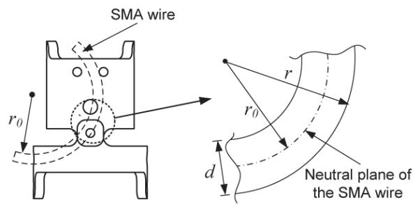
Correction of strain to the radius of curvature.
Fig. 8.
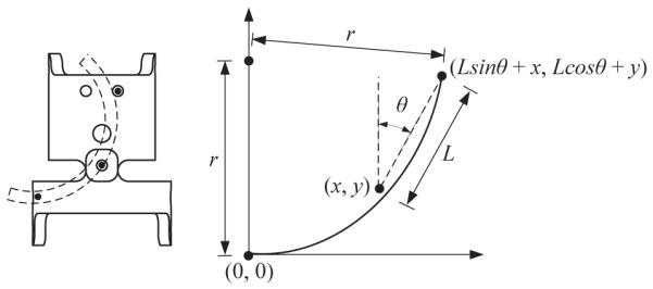
Correction of the radius of curvature to joint displacement.
To summarize, we can measure the temperature of SMA wires by thermocouples and use Eq. (5) to compute the strain in the wire. After obtaining the strain, we can use Eq. (8) to derive the radius of curvature of the wire and then compute the rotation of each joint by using Eq. (9). Thus, we can predict the bending displacement of each joint of MINIR by knowing the temperature and thus the tip position of MINIR can be computed by forward kinematics. Essentially, this approach enables us to control the tip of the robot by monitoring the temperature of the wire through the thermocouples attached to each SMA actuator.
V. IMPLEMENTATION OF PWM CONTROLLER
Since the motion of MINIR can be reliably predicted by the temperature of SMA actuators, we needed to implement a controller to control the temperature of SMA wires. PWM is a powerful technique to control analog circuits by using a digital output and therefore makes the system robust to disturbance. We implemented a switching circuit to realize PWM control. The circuit is comprised of four switches, four SMA wires and a DC power supply. Note that only one power supply is required to control four SMA wires using this circuit. The DC power supply is used to provide a constant current. The PWM control signal is used to control the state of the switches and it thus converts the continuously supplied current into an equivalent PWM output command, which activates the corresponding SMA wire and thereby induces joint motion. By switching current to the SMA wires at a high frequency, multiple SMA wires can be heated up and maintained at a constant temperature by using only one power supply.
The goal of this control scheme was to control the temperatures of multiple SMA wires simultaneously and independently by using one power supply. The position commands of each joint were then mapped to temperature commands (Tset) by following the steps described in section IV. The measured temperature (Tcurrent) of each SMA wire was monitored by thermocouples. If the difference between Tset and Tcurrent for a specific SMA wire was larger than a threshold (δ), the heating time (t) was computed by the PI controller in Eq. (10). The heating time, t, can be adjusted to change the system performance and it is given by:
| (10) |
where the error, e, is defined as (Tset – Tcurrent). This control command (t) was the width of the “on” signal of a PWM signal and it was sent to the switching circuits and the corresponding switch would close for t seconds, enabling the assigned SMA wire to be heated for t seconds. This time period should be limited to an upper value (tmax), which was used to prevent the temperature drop of other SMA wires. When the wire was heated to a desired temperature (Tset) or heated up for tmax seconds, the control system switches to monitor the next SMA wire and therefore keeps all wires under control. If (e < δ), the system will switch to monitor next SMA wire immediately. The frequency of the control cycle should be high enough to prevent temperature drop.
VI. RESULTS AND DISCUSSIONS
A. SMA wire characterization
Due to the antagonistic SMA wire setup of MINIR, the unactuated SMA wire will be naturally deformed by the joint motion due to the actuated SMA wire. Therefore, we only need to characterize the heating process and the hysteresis behavior of SMA can be ignored. Thus, only As and Af are required to be determined in this experiment. In section III-B, we have seen that As and Af are important parameters in the constitutive model and the accurate measurement of them was necessary for predicting the material behavior during the heating process. Note that these transformation temperatures are often defined for the material in a stress-free condition, because they change as a function of applied stress. As mentioned before, the experimental setup presented in this paper is capable of measuring SMA wire parameters which are necessary for developing the analytical model. To determine the transformation temperatures of a single SMA wire under zero stress condition, we put the SMA wire on the testing device as shown in Fig. 9(a).
Fig. 9.
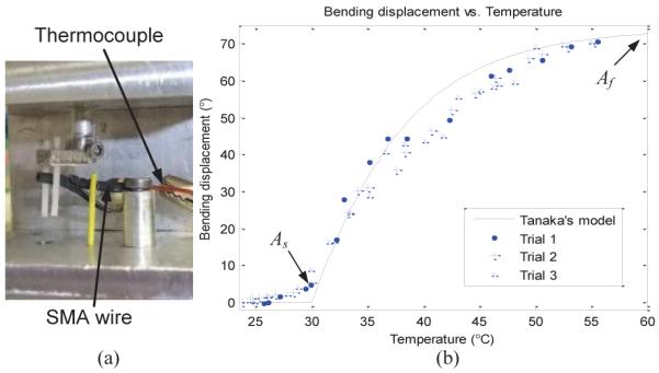
(a) Experimental setup for the testing of a SMA wire, (b) Bending displacement vs.temperature curve of a SMA wire.
The SMA wire was initially at room temperature in the pre-strained condition and a constant current was applied across the SMA wire, which caused the temperature of the wire to increase due to internal heating. As the temperature increased beyond As, the wire started to recover its original unstrained geometry. The experimental results are shown in Fig. 9(b), and As, Af can be easily defined from the figure. The solid line in Fig. 9(b) is computed using Tanaka’s model and the material parameters are shown in Table I. Elastic moduli and the maximum recoverable strain were provided by the manufacturer. Initial strain of the SMA wire is computed from the geometry of the robot and the transformation temperatures are obtained from the experiment.
TABLE I.
SMA WIRE PARAMETERS
| Elastic moduli | Transformation temperatures | Strain |
|---|---|---|
| EA = 70 GPa | As = 30 °C | εL = 0.067 |
| EM = 28.7 GPa | Af = 60 °C | ε0 = 0.026 |
The As of the SMA wire we used in this experiment is lower than human body temperature. It seems not suitable for our neurosurgical application, however, it is well-known that the transformation temperatures of SMA can be tuned through heat treatment [26]. Typically, the austenite finish temperature ranges from 25°C to 75°C. Hence in our future prototype for tissue experiments, we plan to have SMA with 40°C As and 55°C Af to prevent actuating by body temperature or damaging the healthy tissue. Furthermore, the robot will be shielded by polymer skin, which will act as an insulator.
B. Joint motion
1) Single wire actuation: Comparison with the theoretical model
We did experiments (one SMA wire was attached to the joint) to demonstrate that the motion of MINIR was consistent with the theoretical model presented in section III. The SMA wire was pre-strained as in Fig. 5 and the thermocouple was placed at the center of the SMA wire. We assumed that the resistance was consistent along the length of the SMA wire and that the SMA wire was heated uniformly. Current was then applied to the SMA wire and the thermocouple readings and bending displacement were recorded continuously. The experimental setup is as shown in Fig. 10(a). The experimental result is shown in Fig. 10(b). The solid line in the figure is Tanaka’s model using the same parameters as used in Fig. 9(b). The maximum error between the experimental results and the theoretical model was 5.5° while the average error and standard deviation was 0.1° and 2.7°, respectively. The 5.5° maximum error leads to a 0.69 mm error in the horizontal displacement. Note that the maximum bending displacement shown in the figures were due to the geometric limit of the joint motion.
Fig. 10.
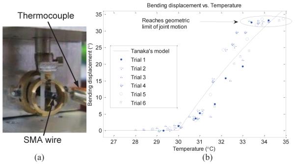
(a) Experimental setup for the testing of a one-link MINIR, (b) Bending displacement vs.temperature curve for a one-link MINIR.
2) Two antagonistic wire actuation
Next, we actuated two antagonistic SMA wires attached at a joint to enable the link to move back and forth several times. The experimental setup and the procedure is essentially the same as in section VI-A. The average maximum bending displacement was about ±30°, as shown in Fig. 11 and the joint motion was observed to be repeatable across several trials with a standard deviation of 2°. During heating, the response time (from 0° to 30°) ranges from 12 seconds to 20 seconds, depending on the applied current, which is much faster than cooling time (35 seconds under natural cooling). Since the entire neurosurgical procedure can take a few hours to complete, the slow response of SMA is not a disadvantage in our application. In fact, the robot should move slowly during electrocauterization to ensure that the tumor has been completely removed.
Fig. 11.
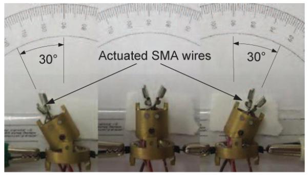
One link of MINIR actuated by two antagonistic SMA wires.
C. PWM control with temperature feedback
For PWM control, we used the DAQ card to generate digital on/off signal and the control loop frequency was set to 20Hz. Based on the open-loop heating and cooling response tests of SMA wires, the temperature difference threshold (δ) was set to 0.5°C and the maximum heating period (tmax) was set to 0.3 second. For the switching circuit, we chose to use solid state relays (SSRs) as switches. SSRs are more compact and faster than electromechanical relays. Their switching time is on the order of milliseconds, which satisfies our requirement of high frequency switching.
In the experiment, we heated four SMA wires up to 60°C independently by using one power supply and the experimental results are shown in Fig. 12. The results showed that the controller is capable of heating multiple SMA wires while maintaining the temperature of other wires and only one power supply is needed. At steady state, the average error, e (in temperature) was −0.09°C and the standard deviation was 0.58°C. The various slopes of the data are the heating rates for each wire. It is obvious that the heating rates of SMA wire #4 is slower than that of wire #1 because the controller had to maintain the temperatures of other SMA wires while heating SMA wire #4. Since the energy provided by the power supply is constant, when more wires are controlled, the heating rates are slower. Through this temperature control test and the previously described bending displacement vs. temperature results, we can control the motion of each joint of MINIR simultaneously and independently by using the PWM control scheme with temperature feedback.
Fig. 12.
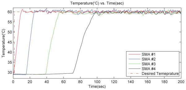
Test of the PWM temperature control.
D. Motion test in gelatin
In our application, MINIR should be able to move in a tightly enclosed environment (human brain). Thus, we need to ensure that the force generated by the SMA wire is sufficient to move the robot link. To understand the force-temperature relationship, we investigated the constrained recovery behaviour of MINIR. Constrained recovery means that the wire is kept at constant strain and the testing involves measurement of generated force-temperature relationship under different strain conditions, i.e., different bending displacements of the joints. We found that the maximum force that can be generated at the distal end of each link was about 1.5N with a 0.5mm SMA wire. This maximum force was recorded when the SMA wire was heated to 85°C and the bending displacement was 0°. Furthermore, to make sure that MINIR can be actuated inside a human brain, we tested the 3-DOF MINIR in a gelatin medium which served as a brain tissue substitute. The 3-DOF robot has six SMA wires and six thermocouples inside. The gelatin was mixed at a ratio of 200 ml boiling water to 13 ml gelatin powder (Knox gelatin, Kraft Foods Global Inc.). This mixture has been proposed in the literature [27] as an artificial brain tissue substitute.
We first actuated the tip link by heating up the SMA wire to 50°C and then the second link with a SMA temperature of 60°C followed by bottom link which was heated up to 60°C. The test results are shown in Fig. 13, and the width of each grid is 3.2mm. The experimental results clearly demonstrated that the 3-DOF robot is able to move in a tightly enclosed environment and push the gelatin away. The horizontal displacement of the robot tip is about 20mm which is of the order of the size of a brain tumor.
Fig. 13.
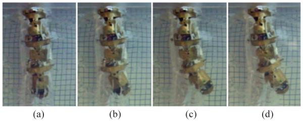
Test of the 3-DOF robot in gelatin. (a) Neutral position, (b) Tip link was actuated with a temperature of 50°C, (c) Second link was actuated with a temperature of 60°C and (d) Bottom link was actuated with a temperature of 60°C.
E. Test in MRI
1) Motion test in MRI
We then actuated a 2-DOF MINIR in a 3-Tesla MRI to verify the MRI compatibility and to make sure that the range of motion is not affected by the strong magnetic field. We put the robot at the center of the MRI bore and actuated it. The test results showed that MINIR can be moved back and forth in the MRI bore (see Fig. 14) without significant interference from the strong magnetic field. The bending displacement of the base link was about ±25°. The motion range was smaller than the result in Fig.11 because one more link was added.
Fig. 14.
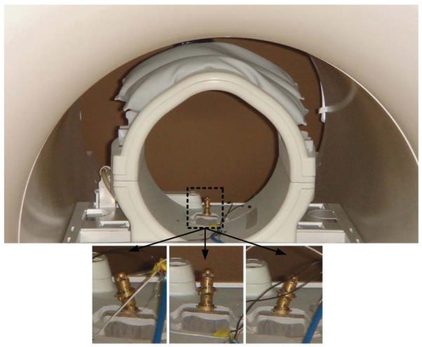
Test of the 2-DOF robot in MRI.
2) MR images of individual links
To evaluate the MR image quality, we first took MR images of the two major links of MINIR to show that the material created no significant distortion in the MR images. We then quantify the induced disturbance to the images by computing the signal-to-noise ratio (SNR) of the images, where SNR is defined as the ratio of the mean pixel intensity of signal in a region of interest (ROI) and the standard deviation of the pixel intensity of the background noise in a ROI. The links were put inside water when taking MR images. The SNR value computed without any links in the water was 111.7 and the SNR value with the links in water was computed to be 88.4. Though there was a decrease in the SNR value from the ground truth, it was still high and we were able to identify the various link components in the MR image as shown in Fig. 15. The bright white spots in the images were caused by the sharp edges of the link profiles, which could be easily fixed by rounding the edges.
Fig. 15.
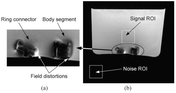
MR Images of the major links of MINIR: (a) Side view of the links and (b) The regions of interest used to compute SNR.
3) MR images of the static 2-DOF MINIR in gelatin
We then put the 2-DOF MINIR in the gelatin with all wiring inside the robot but not actuated. This test is to evaluate the MR image quality of a 2-DOF MINIR in gelatin. The robot is fully surrounded by gelatin to simulate the tightly enclosed environment in a brain. We added 1% Omniscan™ (gadodiamide) injection liquid to the gelatin to increase the contrast of the MR image and the SNR of gelatin was computed to be 40.7. The testing setup is shown as Fig. 16(a) and the result is shown as Fig. 16(b). The SNR of the image with the MINIR in gelatin was computed to be 34.0. The reasons for the decreasing SNR are the existing of metal parts and conductive wires. When taking MR images, the magnetic field through the MRI bore is changing. The varying magnetic field can generate Eddy current on a conductive object and thus brought noise to MRI. The other reason is that the conductive wires served like antennas, which collected all noise in the MRI room and thus reduced the SNR. The Eddy current on the MINIR links can be avoided by replacing brass links with plastic ones, and which is the other undergoing part of this project [28]. The antenna effect can be minimized by using shield cables. However, since the profile and the tip position of the robot are identifiable in the image and there is no significant distortion on the surrounding gelatin, we will continue to use the brass prototype to do the following tests at this stage.
Fig. 16.
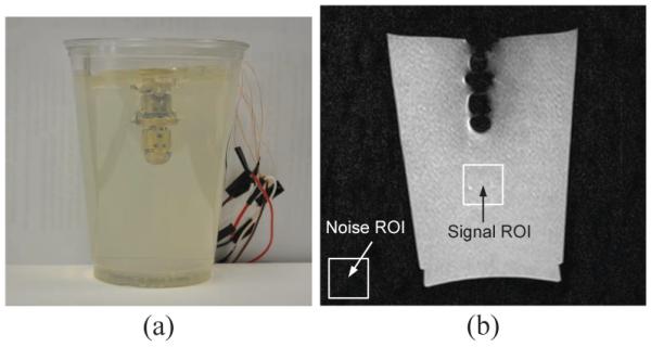
Static MR image of the 2-DOF MINIR in gelatin.
4) MR images of the actuated 2-DOF MINIR in gelatin
Finally, we tested the motion of the 2-DOF MINIR under continuous MRI. It moved back and forth successfully in gelatin and created no significant distortion in the images. The experimental result is shown as Fig. 17, the figure shows three different positions of MINIR when actuated inside MRI bore. The profile of the robot is clear and the tip position can be easily identified in the images. We observed very little phase variations which is indicative of magnetic field distortion in the images during the operation of MINIR. These minor phase variations led to some field distortions around MINIR but this distortion did not lead to image loss or the inability to see the complete object. There were totally 200 images taken during the actuation and we have computed the SNR value of each image and it is shown in Fig. 18. MINIR was actuated at the 15th second. The average SNR value before actuation was computed to be 47.8 and it dropped to 42.8 after actuation. The SNR value only dropped by about 10%, which implies that passing the current through MINIR did not cause significant noise in the MR images.
Fig. 17.
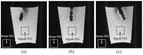
Continuous MR images of the 2-DOF MINIR in gelatin.
Fig. 18.
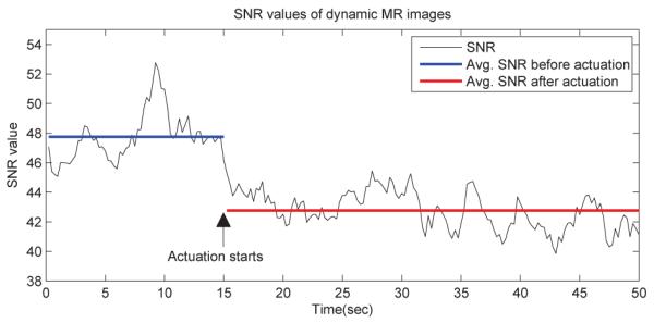
SNR values of dynamic MR images.
The result also provided a feasibility that the surgeon can track the tip position of the robot visually under continuous MRI when performing deep brain tumor resection. Which can help surgeons to remove brain tumor completely while minimizing trauma to the surrounding healthy brain during intracranial procedures.
VII. Conclusion
In this paper, we have presented a new design for the MINIR prototype. In this new design, each joint can be independently actuated and all wiring can be put inside the robot. This new design gives MINIR a larger motion range and better controllability than before. An experimental setup for obtaining parameters of analytical model was also presented. We further investigated the behavior of the SMA wire and determined material parameters from experiments. The experimental results of one-link test showed that the motion is repeatable and predictable using Tanaka’s model. Moreover, we successfully used PWM and switching circuits to control multiple joints, i.e., SMA wires, simultaneously and independently using only one power supply with temperature feedback. We also measured the maximum force that can be generated by each link of the robot. We evaluated the motion of the robot in gelatin and observed that the motion was within the range of expected motion for neurosurgical application. We noticed that when more links are added to MINIR, the bending displacement for the joint was not the same for all joints while the motion was repeatable for a single link. However, this is expected since additional loading on the proximal link due to distal links causes increased stress on the SMA wire. This can be addressed by using larger diameter SMA wires for the base joint compared to the distal joints in our future prototype.
We then demonstrated that the robot is MRI-compatible by actuating it in the MRI bore and similar range of motion was observed. We also took continuous and static MR images of the robot and the results showed very limited distortion which will not effect the image quality of the surrounding tissue. The high SNR of MR images showed that it is possible to track the tip position of the robot by MR images and which can be used to verify the positioning accuracy of our temperature feedback control scheme. Furthermore, the robot profile can also be easily identified in the continuous MR images. Which provided a possibility to use the MR images as visual feedback for operators when performing a deep brain tumor resection and therefore greatly increase the survival rate of patients who suffered from this most feared complications of cancer.
Our future work in this area will involve adding more links to MINIR as well as doing more studies in the MRI by actuating the robot in ex-vivo tissue followed by in-vivo swine model studies.
Acknowledgments
This work was supported by the National Institutes of Health (NIH) grant R21EB008796.
Biography

Mingyen Ho (S’09) received his B.S. and M.S. degrees in Mechanical Engineering from the National Tsing Hua University, Taiwan, in 2003 and 2005, respectively. He is currently a graduate student in the University of Maryland, College Park, working as a graduate research assistant in the Robotics, Automation, and Medical Systems (RAMS) Laboratory.

Alan B. McMillan received the B.S., M.S., and Ph.D. degrees in biomedical engineering from the University of Wisconsin, Madison, in 2002, 2004, and 2007, respectively. He is currently an Assistant Professor of Diagnostic Radiology and Nuclear Medicine, University of Maryland School of Medicine, Baltimore. His research interests include rapid MR imaging and reconstruction techniques, including interventional, dynamic, and functional MR imaging.

J. Marc Simard is a clinical neurosurgeon and an experienced investigative scientist. He received his B.A. in Chemistry in 1972 from the St. Anselm College and received his M.D., Ph.D. degree in Medicine in 1980 from the Creighton University. He is responsible for the original discovery of the Sur1/Trpm4 channel (a.k.a., Sur1-regulated NCCa–ATP channel) nearly 10 years ago. He runs an active laboratory focused on acute CNS pathology that employs numerous scientists with expertise in patch clamp electrophysiology, molecular biology, transcriptional regulation, and preclinical models of disease. In recent years, the laboratory has become focused increasingly on studies of the Sur1/Trpm4 channel in diseases such as stroke, traumatic brain injury (TBI), spinal cord injury and, more recently, in hemorrhagic forms of encephalopathy of prematurity such as germinal matrix hemorrhage. His work on the Sur1/Trpm4 channel has led to the award of 3 patents and filings for numerous other patents. Notably, this work has matured to the point that a clinical trial in TBI and one in stroke are in the early phases of patient recruitment. The promising preliminary data presented in the current application suggests that hemorrhagic forms of encephalopathy of prematurity may become yet another indication for treatment targeting this pathological pathway.

Rao Gullapalli received his post-graduate degree in chemical engineering and received the Ph.D. degree in instrumental sciences from the University of Arkansas, Fayetteville. At the University of Arkansas, he was involved in research on biomedical imaging. He was a Senior Scientist in the Magnetic Resonance Imaging Division of Picker International, Cleveland, OH. He was instrumental in the development of several rapid imaging techniques and establishing research collaborations at various clinical sites. He joined the Department of Radiology, University of Maryland School of Medicine, Baltimore, in 1996 as an Assistant Professor, where he is currently an Associate Professor and Director of the Core of Translational Research in Imaging at Maryland (C-TRIM), and the Magnetic Resonance Research Center. His research interests include the development of multispectral imaging and real-time interventional imaging techniques using magnetic resonance.

Jaydev P. Desai (SM’07) is currently an Associate Professor in the Department of Mechanical Engineering at University of Maryland, College Park (UMCP) and the Director of the Robotics, Automation, and Medical Systems (RAMS) Laboratory. He completed his undergraduate studies from the Indian Institute of Technology, Bombay, India, in 1993 with a B.Tech degree. He received his M.A. in Mathematics in 1997, M.S. and Ph.D. in Mechanical Engineering and Applied Mechanics in 1995 and 1998 respectively, all from the University of Pennsylvania. He is a recipient of the NSF CAREER award and the Ralph R. Teetor Educational Award. He was an invited speaker at the 2011 National Academy of Sciences Distinctive Voices @ The Beckman Center and has also been invited to attend the National Academy of Engineering’s (NAE) 2011 U.S. Frontiers of Engineering Symposium. His research interests include image-guided surgical robotics, haptics, reality-based soft-tissue modeling for surgical simulation, model-based teleoperation in robot-assisted surgery, and cellular manipulation. He is currently the member of the Haptics Symposium Committee, co-chair of the Surgical Robotics Technical Committee of IEEE Robotics and Automation Society, and a member of the Editorial board of IEEE Transactions on Biomedical Engineering and IEEE Transactions on Information Technology in Biomedicine. He is also a member of the ASME and IEEE.
Footnotes
A portion of the content of this paper has been published in: 1) M. Ho and J. P. Desai, “Characterization of SMA actuator for applications in robotic neurosurgery,” in Proc. Int. Conf. IEEE Engineering in Medicine and Biology Society, pp. 6856-6859, 2009 and 2) M. Ho and J. P. Desai, “Towards a MRI-compatible meso-scale SMA-actuated robot using PWM control,” in Proc. IEEE RAS and EMBS Int. Conf. Biomedical Robotics and Biomechatronics, pp. 361-366, 2010.
Contributor Information
Mingyen Ho, with the Robotics, Automation, and Medical Systems (RAMS) Laboratory, Department of Mechanical Engineering, University of Maryland, College Park, MD 20742 USA; with the Maryland Robotics Center, Institute for Systems Research, University of Maryland, College Park, MD 20742 USA myho@umd.edu.
Alan McMillan, with the University of Maryland School of Medicine, Baltimore, MD 21201 USA amcmillan@umm.edu.
J. Marc Simard, with the University of Maryland School of Medicine, Baltimore, MD 21201 USA msimard@smail.umaryland.edu.
Rao Gullapalli, with the University of Maryland School of Medicine, Baltimore, MD 21201 USA rgullapalli@umm.edu.
Jaydev P. Desai, with the Robotics, Automation, and Medical Systems (RAMS) Laboratory, Department of Mechanical Engineering, University of Maryland, College Park, MD 20742 USA; with the Maryland Robotics Center, Institute for Systems Research, University of Maryland, College Park, MD 20742 USA jaydev@umd.edu.
References
- [1].Siker ML, Mehta MP. Resection versus radiosurgery for patients with brain metastases. Future oncology. 2007;vol. 3(no. 1):95–102. doi: 10.2217/14796694.3.1.95. [DOI] [PubMed] [Google Scholar]
- [2].Masamune K, Kobayashi E, Masutani Y, Suzuki M, Dohi T, Iseki H, Takakura K. Development of an MRI-compatible needle insertion manipulator for stereotactic neurosurgery. J. Image Guided Surgery. 1995;vol. 1(no. 4):242–248. doi: 10.1002/(SICI)1522-712X(1995)1:4<242::AID-IGS7>3.0.CO;2-A. [DOI] [PubMed] [Google Scholar]
- [3].Chinzei K, Miller K. Towards MRI guided surgical manipulator. Medical science monitor. 2001;vol. 7(no. 1):153–163. [PubMed] [Google Scholar]
- [4].Webster RJ, III, Okamura AM, Cowan NJ. Toward active cannulas: Miniature snake-like surgical robots. Proc. IEEE/RSJ Int. Conf. Intelligent Robots and Systems. 2006:2857–2863. [Google Scholar]
- [5].Degani A, Choset H, Wolf A, Ota T, Zenati MA. Percutaneous intrapericardial interventions using a highly articulated robotic probe. Proc. IEEE RAS and EMBS Int. Conf. Biomedical Robotics and Biomechatronics.2006. pp. 7–12. [Google Scholar]
- [6].Xu K, Simaan N. Analytic formulation for kinematics, statics, and shape restoration of multibackbone continuum robots via elliptic integrals. ASME J. Mechanisms and Robotics. 2010;vol. 2(no. 1):011 006–1–011 006–13. [Google Scholar]
- [7].Wang Y, Cole GA, Su H, Pilitsis JG, Fischer GS. MRI compatibility evaluation of a piezoelectric actuator system for a neural interventional robot. Proc. Int. Conf. IEEE Engineering in Medicine and Biology Society; 2009. pp. 6072–6075. [DOI] [PubMed] [Google Scholar]
- [8].Gilfrich JV, Buehler WJ, Wiley RC. Effect of low-temperature phase changes on the mechanical properties of alloys near composition NiTi. J. Applied Physics. 1963;vol. 34:1475–1477. [Google Scholar]
- [9].Pieczyska E, Gadaj S, Nowacki W, Hoshio K, Makino Y, Tobushi H. Characteristics of energy storage and dissipation in TiNi shape memory alloy. Science and Technology of Advanced Materials. 2005;vol. 6(no. 8):889–894. [Google Scholar]
- [10].Liang C, Rogers CA. Design of shape memory alloy springs with applications in vibration control. J. Intelligent Material Systems and Structures. 1997;vol. 8(no. 4):314–322. [Google Scholar]
- [11].Pappafotis N, Bejgerowski W, Gullapalli R, Simard M, Gupta SK, Desai JP. Towards design and fabrication of a miniature MRI-compatible robot for applications in neurosurgery. Proc. ASME Int. Design Engineering Technical Conf. & Computers and Information in Engineering Conf..2008. [Google Scholar]
- [12].Shaw JA, Churchill CB, Iadicola MA. Tips and tricks for characterizing shape memory alloy wire: Part 1 - Differential scanning calorimetry and basic phenomena. Experimental Techniques. 2008;vol. 32(no. 5):55–62. [Google Scholar]
- [13].Churchill CB, Shaw JA, Iadicola MA. Tips and tricks for characterizing shape memory alloy wire: Part 2 - Fundamental isothermal responses. Experimental Techniques. 2009;vol. 33(no. 1):51–62. [Google Scholar]
- [14].Lagoudas DC, Entchev PB, Kumar PK. Thermomechanical characterization of SMA actuators under cyclic loading. Proc. ASME Int. Mechanical Engineering Congress and R&D Expo.2003. [Google Scholar]
- [15].Kode VRC, Cavusoglu MC. Design and characterization of a novel hybrid actuator using shape memory alloy and DC micromotor for minimally invasive surgery applications. IEEE/ASME Trans. Mechatronics. 2007;vol. 12(no. 4):455–464. [Google Scholar]
- [16].Ma N, Song G. Control of shape memory alloy actuator using pulse width modulation. Smart Mater. Struct. 2003;vol. 12(no. 5):712–719. [Google Scholar]
- [17].Price AD, Jnifene A, Naguib HE. Design and control of a shape memory alloy based dexterous robot hand. Smart Mater. Struct. 2007;vol. 16(no. 4):1401–1414. [Google Scholar]
- [18].Bundhoo V, Haslam E, Birch B, Park EJ. A shape memory alloy-based tendon-driven actuation system for biomimetic artificial fingers, part I: design and evaluation. Robotica. 2009;vol. 27(no. 1):131–146. [Google Scholar]
- [19].Gilardi G, Haslam E, Bundhoo V, Park EJ. A shape memory alloy-based tendon-driven actuation system for biomimetic artificial fingers, part II: modelling and control. Robotica. 2010;vol. 28(no. 5):675–687. [Google Scholar]
- [20].Ho M, Desai JP. Characterization of SMA actuator for applications in robotic neurosurgery. Proc. Int. Conf. IEEE Engineering in Medicine and Biology Society; 2009. pp. 6856–6859. [DOI] [PubMed] [Google Scholar]
- [21]. — Towards a MRI-compatible meso-scale SMA-actuated robot using PWM control. Proc. IEEE RAS and EMBS Int. Conf. Biomedical Robotics and Biomechatronics.2010. pp. 361–366. [Google Scholar]
- [22].Tanaka K. A thermomechanical sketch of shape memory effect: One-dimensional tensile behavior. Res. Mechanica. 1986;vol. 18(no. 3):251–263. [Google Scholar]
- [23].Liang C, Rogers CA. One-dimensional thermo mechanical constitutive relations for shape memory material. J. Intelligent Materials and Structures. 1990;vol. 1(no. 2):207–230. [Google Scholar]
- [24].Brinson LC. One-dimensional constitutive behavior of shape memory alloys: Thermomechanical derivation with non-constant material functions and redefined martensite internal variable. J. Intelligent Materials and Structures. 1993;vol. 4(no. 2):229–242. [Google Scholar]
- [25].Johnson Matthey Medical, Nitinol technical data. http://www.jmmedical.com/resources.html.
- [26].Morgan NB, Broadley M. Taking the art out of smart! Forming processes and durability issues for the application of NiTi shape memory alloys in medical devices. Proc. of the Materials and Processes for Medical Devices Conf..2003. pp. 247–252. [Google Scholar]
- [27].Engh JA, Podnar G, Kondziolka D, Riviere C. Toward effective needle steering in brain tissue. Proc. Int. Conf. IEEE Engineering in Medicine and Biology Society; 2006. pp. 559–562. [DOI] [PubMed] [Google Scholar]
- [28].Ananthanarayanan A, Gupta SK, Bruck HA. Characterization and control of plastic deformation in mesoscale premolded components to realize in-mold assembled mesoscale revolute joints. Polymer Engineering and Science. 2009;vol. 49(no. 2):293–304. [Google Scholar]


