Abstract
Medical ultrasound imaging has advanced dramatically since its introduction only a few decades ago. This paper provides a short historical background, and then briefly describes many of the system features and concepts required in a modern commercial ultrasound system. The topics addressed include array beam formation, steering and focusing; array and matrix transducers; echo image formation; tissue harmonic imaging; speckle reduction through frequency and spatial compounding, and image processing; tissue aberration; Doppler flow detection; and system architectures. It then describes some of the more practical aspects of ultrasound system design necessary to be taken into account for today's marketplace. It finally discusses the recent explosion of portable and handheld devices and their potential to expand the clinical footprint of ultrasound into regions of the world where medical care is practically non-existent. Throughout the article reference is made to ways in which ultrasound imaging has benefited from advances in the commercial electronics industry. It is meant to be an overview of the field as an introduction to other more detailed papers in this special issue.
Keywords: medical, ultrasound, systems
1. Introduction
Medical ultrasound systems have experienced a revolution in recent years owing to increasing compute power of modern electronics. Capabilities considered to be a fantasy only a few years ago are now taken for granted. In many ways, these advances mirror those in the consumer electronics industry and make use of them. Computing power has dramatically increased ultrasound system capability, but it has also significantly widened the application space in which ultrasound can be found. Ultrasound is now being used in doctors' offices, emergency departments, ambulances, surgical intervention suites and in developing countries with little access to medical imaging technology. Miniaturization of other components enables the body to be visualized from within the oesophagus and even inside blood vessels and the heart. This paper will describe the state of the art in ultrasound systems and some of the technologies that are now commonplace, though many are only a few years old. Other papers in this special edition will describe some of the more novel technologies that are less fully developed.
2. Beam formation
2.1. Early evolution
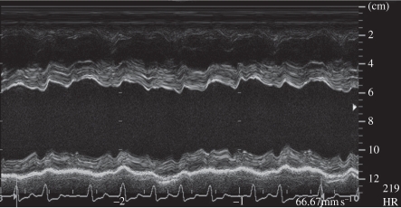
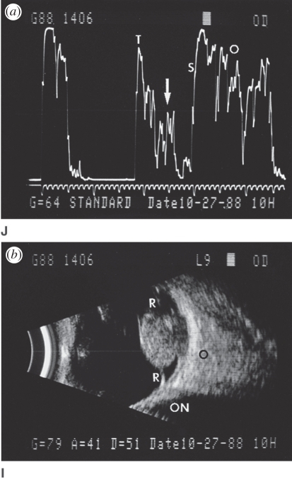
The first ultrasound systems consisted of a handheld transducer that pointed a beam directly in line with its handle. The signal amplitude was proportional to the strength of the reflected signal. This A-mode was mostly of academic interest until motion, or M-mode, was developed in which the signal amplitude was displayed as a function of time (figure 1) [1]. Cardiologists were then able to visualize the motion of heart valves, diagnosing many cardiac valvular anomalies. Two-dimensional brightness, or B-mode, was developed using position-sensing arms to record the location and direction of the ultrasound beam to provide the first ultrasound imaging (figure 2).
Figure 1.
M-mode echocardiogram showing cardiac wall motion over time. (From Kremkau [1].)
Figure 2.
(a) A single amplitude (A-mode) line is used to produce a B-mode image (b) when swept throughout the scan plane. (From Kremkau [1].)
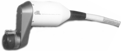
The first real-time ultrasound was developed in the late 1970s by placing three transducers on a rotating wheel, which allowed the system to keep track of where the transducer was pointing within the image plane. This early real-time B-mode led to a more rapid adoption of ultrasound as an established medical imaging technique (figure 3) [2].
Figure 3.
Early mechanically scanned transducer with the motor in the handle and three belt-driven transducers on the wheel.
2.2. Array beamforming
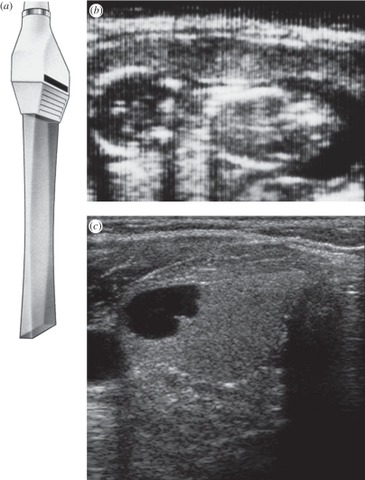
The complexity and reliability issues of mechanically scanned transducers led to the development of array systems in which the beam is steered electronically, transmitting sound from a series of ultrasonically active elements in the transducer. Linear arrays step the beam along the transducer and produce images with full image width up to the skin's surface (figure 4). This was first widely used to image pregnancy as near-field image width is important given the shallow depth of the foetus, and the sound was, and still is, considered to be harmless to the developing foetus.
Figure 4.
Linear array scan showing (a) transducer and scan plane geometry; (b) early OB linear array image showing vertical scan lines; and (c) a modern linear array image. (From Kremkau [1].)
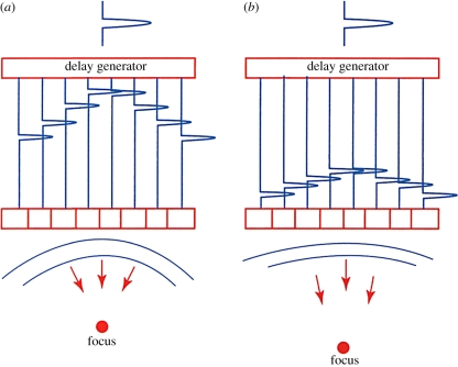
It was soon found that the image could be significantly improved by focusing the beam as a function of image depth. Reflected sound arrives first at the centre of the array and a few microseconds later at the outer edges. By delaying the sound at the centre until it is in phase with that coming from the outer edges, a much more tightly focused beam can be generated. Owing to the principle of reciprocity, the transmit beam can also be focused by applying the transmit pulse earlier to the outer elements. By changing the delay curvature, the beam may be focused at different depths (figure 5).
Figure 5.
Array focusing showing delays for close focus (a) and far focus (b). (From Kremkau [1].)
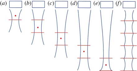
Since the ultrasound beam is generally transmitted by the same transducer as that receiving the reflected signal, and the speed of sound is known, the depth from which a given received signal is also known. This allows dynamic focusing of the received signal in real time so that the received beam is in focus over the entire depth of the image. This is impossible for the transmit beam, as, once it is launched, the system can no longer affect it, so most medical ultrasound systems provide a focal point indication to the user. To obtain optimum focus over the entire depth of field, multi-zone transmit was developed, in which several transmit pulses are sent for each line, focused at a different depth. Then the final image is formed out of the portions of those partial images that are most in focus (figure 6). This has the drawback of reducing the frame rate.
Figure 6.
Multi-zone focus showing: (a–e) progressively deeper focus; (f) uniform focus achieved by blending focal zones. (From Kremkau [1].)
Phased arrays steer the image by changing the phase of the transmitted ultrasound signal from a relatively smaller array, rather than by changing the physical location of the centre of the beam (figure 7). To steer the beam, the signal is transmitted first from the element farthest from the direction of the desired scan direction and sent progressively later to elements closer to the scanline. The signals all line up in phase in the scan direction but interfere destructively with each other elsewhere. This can be combined with focusing described earlier, providing steering and focusing with no moving parts.
Figure 7.
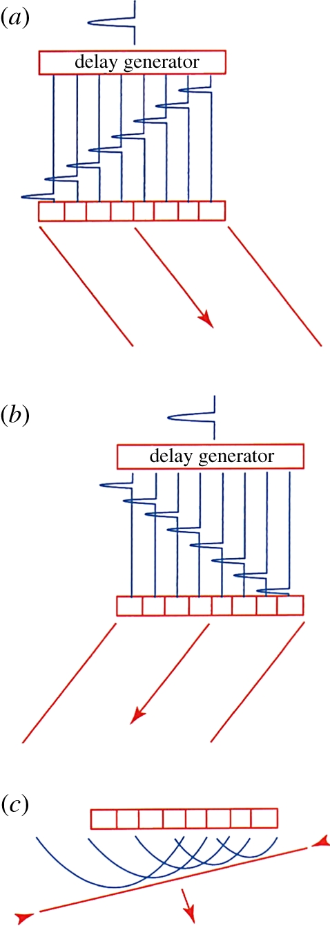
Array steering: (a) delays for steering right; (b) delays for steering left; and (c) wavefronts producing a steered wave. (From Kremkau [1].)
Although the first phased array was developed for use in the brain, phased arrays saw their first major application in cardiology. Since ultrasound is highly attenuated by bone, cardiac images are generally acquired by sending the beam between the ribs. Since the ultrasound beam originates from the same location for each scanline, phased arrays produce a fan beam, perfect for this purpose. Electronic beam steering also enabled the development of simultaneous modes, which was especially important for cardiology. It was now possible to provide a B-mode image in real time with a simultaneous M-mode display, so that cardiologists could see a very detailed view of the motion of a cardiac valve as well as the location from which it was acquired.
Early array systems used analogue switched delay lines to provide the required delays in the received signals, but digital beamforming soon replaced the complex analogue circuitry required. This also provided more flexibility to program new beam sequences, allowing new imaging modes to be developed. The processing requirements for digital array beam steering and focusing are extremely large and have until recently only been done with dedicated electronics, typically custom-designed application-specific integrated circuits (ASICs). For example, a typical array might have 128 elements, each sampled at 20–40 MHz. This requires from 2.5 to 5 billion operations per second just for the receive beam formation process. Since these are repetitive and deterministic actions, ASICs are ideal for this purpose.
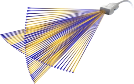
In many applications, frame rate is a critical performance metric. This is especially true for capturing rapidly moving cardiac valves or colour flow imaging that uses multiple pulses to estimate blood flow velocity. The advent of digital beamforming made multiple line parallel processing feasible. In this case, a wider transmit beam is used to cover several look directions at once. Then the receive beamformer forms two or more beams from the same received data by imposing slightly different delays on the received signals. This degrades the resolution slightly, as the transmitted beam is not as tightly focused, but, since most of the focusing effect comes from the receive beamforming, the degradation is minimal, in exchange for the benefit of a factor of two or more increase in frame rate. Parallel beam formation is also critical to three-dimensional scanning as 50–100 scanplanes may be needed to acquire a single volume dataset.
2.3. Doppler flow detection
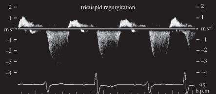
Pulsed Doppler was developed in the 1970s to measure blood flow velocity at a specific location and the result is presented as a velocity or frequency spectrum over time (figure 8). Ultrasound measures the velocity component parallel to the sound beam based on the Doppler equation
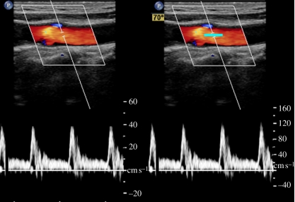
where fD is the measured Doppler frequency, f0 is the ultrasound centre frequency, v is the flow velocity, c is the speed of sound in tissue and θ is the angle between the sound beam and the flow velocity. To compensate for the Doppler angle, an angle cursor is often used to estimate absolute velocity, as shown in figure 9.
Figure 8.
Pulsed wave Doppler showing regurgitant flow in a tricuspid valve.
Figure 9.
Cartid colour and pulsed wave Doppler showing spectrum without (left) and with (right) angle correction on a frozen image (cursor highlighted in cyan for visibility).
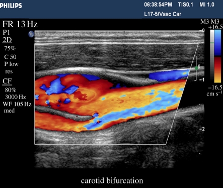
Colour flow imaging was developed in the early 1980s using the beam agility of an array system to rapidly obtain Doppler information throughout the field of view. Colour flow samples the velocity field a few times in each look direction, estimates the principal Doppler frequency component in each location, and creates an image showing the location and axial velocity component of blood flow at every location in the image (figure 10). Colour flow is often used to locate regions of interest, such as high velocity at a stenosis, and then pulsed Doppler is used to quantify the velocity. Since flow velocity direction typically varies over the two-dimensional image, little effort is made to angle correct it. Many academic researchers have proposed novel ways of acquiring the absolute flow direction, usually by acquiring the Doppler signal from different directions simultaneously; none has been commercialized for mainstream use.
Figure 10.
Carotid bifurcation showing complex velocity patterns in a colour flow image.
2.4. Two-dimensional matrix arrays
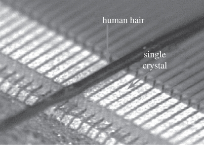
So far we have only discussed focusing and steering azimuthally within the image plane. For two-dimensional scanning, the transducer is diced into a series of longitudinal elements that might be less than 0.5 mm wide, but 10–20 mm long (figure 11). The beam can also be focused in elevation, but until recently this was done with an acoustic lens. The lens configuration is chosen to give good focusing at the typical depth at which a given transducer is expected to be used, but not so strong as to make deeper or shallower locations too far out of focus. In recent years, some manufacturers have introduced elevation plane focusing by dicing the array into a few strips longitudinally, but very little elevational steering was possible.
Figure 11.
Phased array elements compared with the size of a human hair.
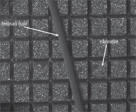
Very recently, two-dimensional arrays have become possible, with the transducer diced completely in both directions into a matrix of transducer elements (figure 12). This allows steering and focusing of the beam anywhere in the image volume electronically and virtually instantaneously. This poses many new challenges. The 128–256 elements in a conventional array are each driven by a tiny coaxial cable housed in a single cable, although this is clearly impossible for an array of 2000–8000 elements. Matrix array beamforming is made possible by integrating part of the beamforming within the transducer itself using new types of custom ASICs. The elements are grouped into 100–200 small patches of elements, which require much smaller delays for steering and focusing. Then each of these is connected to the system with a cable to finish the beam formation with larger digital delays. This new technology blurs the traditional distinction between passive transducer and system since the transmitters, preamps, some beamforming delays and other active electronics reside within the transducer housing.
Figure 12.
Matrix array elements compared with a human hair.
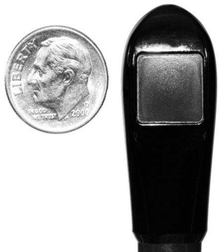
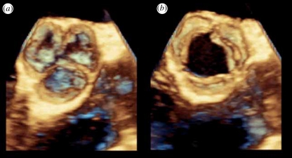
With the continuing size reduction in electronics, matrix arrays can now even be integrated into a volume small enough (figure 13) to be inserted into the oesophagus for real-time three-dimensional scanning of the heart (figure 14). This avoids the image degradation from ribs, lungs and fat layers, especially in obese patients. It also allows cardiac monitoring during surgery as the transducer is out of the way.
Figure 13.
Philips X7-2 matrix transducer for imaging the heart in three dimensions in real time from within the oesophagus.
Figure 14.
Three-dimensional images of an aortic valve acquired in real time from inside the oesophagus with the Philips X7-2 TEE transducer (a) in diastole and (b) in systole.
2.5. Tissue aberration
One aspect of ultrasound imaging that differs significantly from other imaging modalities such as magnetic resonance and computerized tomography is that the ultrasound beam undergoes distortion and aberration depending on the tissue through which it is propagating. One of the simplest forms of aberration is the difference in speed of sound in different tissues. The speed of sound in fat is slightly lower than in most other tissues (1440 m s−1 versus 1540 m s−1), so the assumption the system makes in its beamforming calculations can be slightly wrong, leading to incorrect focusing. Some ultrasound manufacturers have recently introduced a speed of sound correction feature, which takes this into account and can significantly improve image quality, especially in larger patients.
True aberration correction has been pursued academically for many years, in which the system tries to estimate the distortion in the signal at each element by cross-correlation methods. Although this has been made to work in highly controlled experimental situations, it has never been made robust enough to be used in any commercial products. One reason for that failure put forward by many researchers is that the distortion is a two-dimensional problem that cannot be solved with a one-dimensional array. Matrix arrays may remove that drawback, but the processing complexity of per-channel aberration correction is large and the implementation hurdles very high [3–5].
3. Echo image formation
Following beam formation, there are some 64–256 or more lines of radiofrequency (RF) data that represent the acoustic backscattered signal from the different scanning directions. These are typically filtered digitally with a complex bandpass filter to reduce out-of-band noise and simultaneously produce an analytic signal of real and imaginary components. While B-mode imaging does not really need the analytic signal, most other imaging modes such as Doppler and colour flow do, and the same processing hardware can be used for all modes. For B-mode, the analytic signal is detected by taking the square root of the sum of the squares of the real and imaginary components. Other modes will be described in following articles.
3.1. Scan conversion and RF interpolation
The acoustic data are acquired in a spatial format determined largely by the transducer geometry. This must be converted to the orthogonal raster format used for video display. The earliest scan converter was a video camera pointed at an XY oscilloscope display. Today this is all done digitally or in software. The filtered and detected amplitude data are stored in a large memory and the acoustic data needed for each pixel are read and interpolated to produce the final image.
Traditional processing treats each acoustic line as an entity, performing the required filtering and detection down each line independently. In the mid-1990s, it was found that by interpolating the RF data prior to detection the line density could be reduced, increasing frame rate, or tighter focusing could be achieved, increasing resolution. Thus, additional lines of interpolated acoustic data are generated prior to detection and scan conversion.
3.2. Speckle and speckle reduction
A characteristic of ultrasound imaging that differs from other modalities is that it is a coherent process, which leads to constructive and destructive interference when scattered from a diffuse scattering medium. This leads to coherent speckle, much like that seen in a magnified laser beam. There is no known way to analytically remove this speckle but several techniques have been developed to reduce it. Simple spatial smoothing generally degrades spatial resolution to an unacceptable level, so is seldom used.
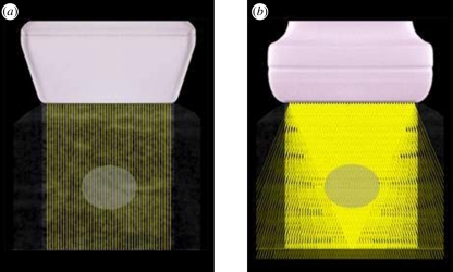
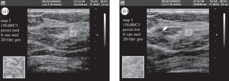
Frequency compounding reduces coherent speckle by detecting the signal at different frequency bands within the transmitted spectrum and combining the results. Since different frequencies have different speckle patterns, the standard deviation of the speckle in the final image is reduced by averaging [6,7]. Spatial compounding is a similar concept, in that frames are generated at different angles (figure 15), which have different speckle patterns, and the final image has reduced speckle owing to the averaging effects (figure 16) [8,9].
Figure 15.
(a) Conventional linear array scan and (b) spatial compounding scan. Image volume is scanned from multiple directions, reducing coherent speckle. The best results are obtained in the centre of the image, where the volume is scanned from the most different directions. (From Kremkau [1].)
Figure 16.
(a) Conventional image and frequency compounded, or SonoCT, (b) image showing the reduced coherent speckle without a reduction in spatial resolution.
Increased computer speeds in recent years have allowed more complex image-processing techniques to also reduce speckle artefacts while preserving image detail. XRES, introduced by Philips, uses multi-resolution image processing to adaptively smooth speckle and enhance structural edges. It involves an analysis phase (in which artefacts and targets are identified) and an enhancement phase (in which artefacts are suppressed and targets enhanced). The analysis phase takes into account multiple characteristics of the target, such as local statistical, textural and structural properties, which are then used in the enhancement phase to select the appropriate spatial filter. For example, smoothing is applied along an interface to improve continuity, while edge enhancement is applied in the perpendicular direction. In regions identified by the analysis phase as being homogeneous (no structure or texture), smoothing is applied equally in all directions. This was the first image-processing technique to see widespread commercial use using advances in general purpose computers, as this processing is much more highly compute intensive than frequency and spatial compounding [10,11].
3.3. Tissue harmonic imaging
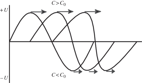
Harmonic imaging, in which a pulse is transmitted at one frequency and received at twice the transmitted frequency, was originally developed to detect the nonlinear vibrations of ultrasound contrast microbubbles. This will be discussed in detail in another article. Early in contrast imaging, however, researchers noticed that the images acquired prior to the arrival of the contrast had better image quality than those made at the fundamental, even at the higher frequency. It had long been known that sound propagating through tissue created harmonics of its centre frequency [12,13]. Tissue (water) is generally considered to be incompressible and the speed of sound independent of pressure. However, at high acoustic amplitudes, sound speed is slightly higher than at ambient pressure and the peak of the sound wave actually travels faster than the local sound speed. Conversely, in the trough, the speed of sound is slower. This leads to peaking of the sound wave, and the creation of harmonics (figure 17).
Figure 17.
Tissue harmonic generation: as the wave propagates, the higher pressure portion of the wave travels faster owing to the higher density of the medium and the lower pressure travels slower, leading to wave distortion and harmonic generation.
Tissue was generally considered to be a linear propagation medium because the harmonics that are generated by the transmitted sound beam are highly attenuated owing to frequency-dependent attenuation. Improvements in transducer bandwidth and beamformer sensitivity allowed these tissue harmonics to be visualized. But what led to the improved image quality?
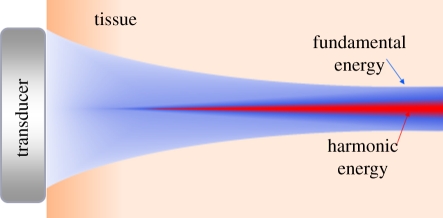
First, the harmonic beam is significantly narrower than the fundamental beam, even one transmitted and received at the higher frequency. Harmonic energy creation is essentially a squaring process, so harmonic energy only gets created where the transmitted beam is at its most intense. Most of the lower intensity energy and sidelobes of the transmitted beam are not sufficiently intense to create harmonic energy, resulting in a narrower beam and better resolution (figure 18).
Figure 18.
Harmonic energy is only created in the central, most intense portion of the beam, resulting in a narrower beam and improved spatial resolution.
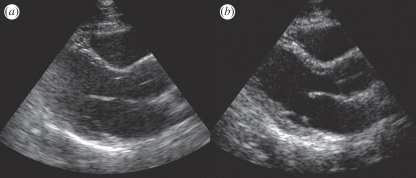
The other aspect of tissue harmonic imaging (THI) that has an even more dramatic effect on image quality is its ability to reduce artefacts from shallow structures. Ultrasound images are often acquired between ribs, or through surface fat layers. Ribs and fat layers produce distortions, reflections and reverberations that can lead to a near-field haze often seen in fundamental imaging. THI reduces this problem because the imaging beam is not created at the skin surface but by the propagating wave, and therefore does not even exist in the first couple of centimetres. Thus, THI significantly reduces overall image clutter, especially in the near field (figure 19) [14–19].
Figure 19.
(a) Fundamental and (b) tissue harmonic images of a difficult cardiac patient showing reduced clutter and improved tissue resolution.
3.4. Three-dimensional imaging
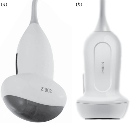
Early three-dimensional imaging used handheld transducers and either made assumptions about the spatial relationship between image planes or used motion sensors to estimate transducer position. This made dimensionally accurate three-dimensional imaging impossible. Later arrays were affixed to mechanisms that wobbled the array from side to side. This provided information as to exactly where the image plane was being acquired and allowed volumetric measurements to be made accurately for the first time. However, the transducers are large, heavy and difficult to use intracostally compared with a matrix transducer (figure 20).
Figure 20.
Three-dimensional imaging transducers showing the (a) 3D 6-2 mechanically oscillating array and (b) the X6-1 matrix transducer.
Three-dimensional scanning provided by matrix array technology provides many additional new features such as X-plane, in which two, often orthogonal, planes are acquired simultaneously (figure 21). This is very useful in both cardiology and general imaging when orthogonal planes are required for volume measurements, especially in rapidly moving structures such as the heart or a foetus in which slower volume rates can be limiting.
Figure 21.
X-plane scanning format using a two-dimensional matrix array. Any planes may be imaged simultaneously.
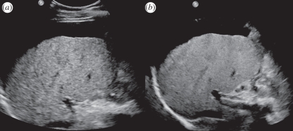
Since conventional arrays are focused in elevation with a fixed lens, compromises in scanplane thickness must be made to obtain reasonable resolution in elevation throughout the depth of field. With full three-dimensional focusing and steering the beam can be optimally focused throughout the depth of field, making the final slice thickness much thinner than can be obtained with a fixed lens (figure 22). Alternatively spatial compounding can be done in elevation with thick slice imaging, where multiple simultaneous thin slice planes are acquired very close together in elevation, and the planes are then combined to form a smoother image, making small structures easier to locate without sacrificing detail.
Figure 22.
Philips X6-1 liver scan comparing (a) conventional imaging and (b) X-Matrix thin slice imaging.
3.5. Panoramic imaging
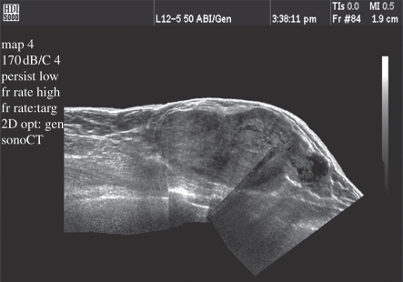
Since the near-field image width is limited by the width of the transducer, it is difficult to obtain a wide view of shallow structures. Panoramic imaging allows the transducer to be moved along the patient's anatomy, blending multiple images together to form one long image with an extremely wide field of view. This feature uses cross-correlation techniques to compare consecutive images, rotating and stitching them together to form the final image (figure 23) [20,21].
Figure 23.
Panoramic image showing increased near-field image width.
4. System architectures
Early ultrasound systems were built using all analogue circuitry with dedicated hardware for each function. The advent of digital processing has increased the flexibility and power of ultrasound systems dramatically. Now most systems use common hardware for all processing, changing the algorithms depending on the imaging mode. The flexibility has also led to the more rapid development of new imaging modes, since the hardware can often be reprogrammed for the new mode, at least for prototype development.
Since ultrasound imaging is almost exclusively real time, data storage is critical. Equally important is understanding and addressing the use model in different geographies. For example, in some countries the physician scans the patient and makes a diagnosis immediately, needing only enough documentation for the patient's record. In other countries, a sonographer scans the patient and sends the images to a review station on the hospital network image storage system. In that model, the physician often does not see the image on the system on which it was acquired, but on a workstation built by a different vendor. The development of standardized image storage formats and compression techniques such as DICOM makes this possible.
4.1. Synthetic aperture
Some newer architectures use synthetic aperture techniques borrowed from radar, in which a broad beam is transmitted covering many look directions, and the received signals from each element are stored into a very large memory. Then the central computer calculates the many beams that could be produced within the broad transmitted beam [22–24]. This is very much like the multi-line processing described earlier, except that the beam formation is done by a programmable computer instead of dedicated beamforming hardware. This has the advantage of potentially extremely high frame rates, but has a trade-off in sensitivity. When the transmitted beam is spread over such a wide area the local power density, and hence sensitivity, is significantly reduced. Also, the computer power required for real-time operation is very high and may impose the limit on frame rate. This does add a new dimension to the many trade-offs in ultrasound system design and may find application in areas where the frame rate is critical and sensitivity less important, or where very rapid acquisition is important but real-time operation is not required.
4.2. Pixel-oriented processing
Related to synthetic aperture is the concept of pixel-oriented processing. Conventional ultrasound processing treats every beam as an entity, beamforming it, filtering it and then scan converting it along with many others into a final image. Alternatively, one can consider an image as a set of pixels, each of which is composed of some raw data that have been processed. One can then back propagate the processing requirements for the pixel being produced, read all the raw data required to produce that pixel, and calculate it individually. As computers become more powerful this concept is starting to gain traction, though it is not yet used in any mainstream ultrasound products.
5. Practical considerations
5.1. Wide range of markets
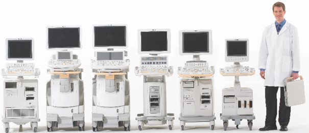
The ultrasound market spans many different clinical applications and economic and geographical markets. It is impractical to design a different system for each of these, so most manufacturers develop their designs for multiple applications, leading to a broad product family to address the different markets (figure 24).
Figure 24.
Philips family of ultrasound systems.
5.2. Ergonomics and workflow
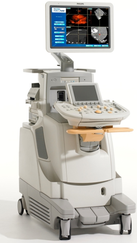
In recent years, repetitive stress injury has been an increasing problem among ultrasonographers. They are often holding the transducer for many hours a day and constantly moving their other hand to press the controls. In addition, they are often required to use systems from different manufacturers, depending on the examination and patient load. In the last few years, a great deal of effort has gone into streamlining the ergonomics of ultrasound systems to reduce fatigue and make their operation more intuitive. The iU22 ultrasound system was designed with ergonomics and ease of use in mind with a movable flat panel display, movable control panel, voice control and touch screen (figure 25).
Figure 25.
Philips iU22 ultrasound system.
As hospital budgets have tightened, workflow and patient throughput have become major factors in ultrasound system design. Every key press that can be eliminated by either automation or well-designed workflow speeds up the examination and improves productivity.
5.3. Regulatory requirements
Medical ultrasound is a highly regulated industry, especially for acoustic output control. There are three key parameters that ultrasound system output must meet. Mechanical index (MI) regulates the peak negative pressure to minimize the likelihood that the ultrasound will cause cavitation. This parameter is a characteristic of any given pulse from a specific aperture design. Spatial peak temporal average (SPTA) regulates the average power that is deposited at any given location in tissue. Surface temperature (ST) regulates how high the temperature can rise at the skin surface.
Generally B-mode echo is limited by MI, as B-mode imaging typically uses a very short burst for optimum axial resolution. Doppler and colour flow, on the other hand, are typically limited by SPTA or ST, as sensitivity is more of a driving factor than resolution. However, as a practical matter, the limits are not so far apart. Colour pulses are often only two to three times as long as the echo pulse for the equivalent application, yet limited by SPTA, not MI. All transducers produce some heat, increasing the ST of the probe. This can come from absorption in the silicone used for lens material, from heat absorbed by the backing within the transducer, or by the ASICs used in matrix probes. Therefore, SPTA and ST are both average power related and in many cases are very close, so that one or the other may limit output power for any given application.
5.4. Pulse compression imaging
One of the many techniques borrowed from radar is coded pulses and pulse compression. All ultrasound system output amplitudes are limited either by regulatory requirements or by internal transmit voltage limitations. Increasing the output power by increasing the burst length degrades axial resolution. This can be avoided by transmitting a coded pulse, such as a frequency-modulated chirp pulse, and performing a matched filter on receive, compressing the received pulse into the autocorrelation function of the transmitted waveform. This allows a long pulse to be transmitted with more energy without sacrificing axial resolution [25–27].
While this sounds appealing, it has its limitations. It can be a powerful technique when the amplitude limit is imposed by transmitter voltage limitations, such as on a portable system. It can also be powerful for ultrasound contrast imaging where the microbubbles are destroyed by high-amplitude ultrasound, requiring very low-transmit voltages. Unfortunately, it provides relatively modest gains for mainstream echo imaging as the burst cannot be lengthened more than a factor of 2 or 3 before encountering the SPTA or thermal limit.
6. Current trends in ultrasound systems
6.1. Portable systems
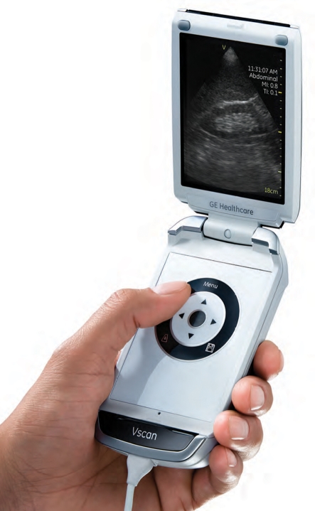
The most visible trend in ultrasound system design is the proliferation of small portable ultrasound systems. While there have been several earlier products they all suffered from incomplete feature sets and/or compromised imaging performance. The rapid increase in processing power and ASIC integration coupled with the development of new battery technologies have allowed the development of handheld and laptop systems with imaging performance nearly equivalent to cart-based systems and battery-powered operating times of 2 h or more. This has allowed ultrasound to find new applications not previously possible for a large cart-based system, such as in emergency departments, ambulances, interventional suites and physicians' offices. The concept of the ‘ultrasound stethoscope’ has been around for many years, but it has now become a reality. Ultrasound systems with excellent image quality can even be carried around in a physician's laboratory coat and are becoming an integrated part of patient care (figure 26).
Figure 26.
VScan handheld ultrasound system from GE. (From Kremkau [1].)
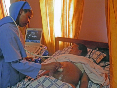
The shrinkage and cost reduction of ultrasound systems have also allowed ultrasound to be used in more remote areas with little previous access to medical imaging technologies. The Imaging the World group is sending physicians with portable ultrasound systems into Africa and other lesser developed areas to provide much needed healthcare to those with little access to it (figure 27). In sub-Saharan Africa, 1 in 16 women die in childbirth, 175 times the rate in the developed world [28]. In remote villages, it may be a 3 day walk to a medical clinic where they can perform a Caesarean section for a breech delivery. If a woman knows she is breech ahead of time, she can get there in time for the Caesarean delivery, but if she does not know until she goes into labour she will most probably die. Ultrasound can play a key life-saving role in that dire situation. Training, education and image transfer then become an important part of the ultrasound ‘system’.
Figure 27.
Compact CX50 in use in a medical clinic in Uganda. Courtesy of Imaging the World.
Image compression techniques not only make hospital networked image storage systems possible, they also make possible transfer of images via cellphone. In remote villages, it is more cost-effective to install a cellphone tower than landlines, and cellphone networks can now transmit images from the villages to centrally located medical centres for more trained opinions. This can also include two-way conversations, which can help to ensure that the images are being acquired correctly.
7. Conclusions
Medical ultrasound systems have gone through a revolution in recent years in terms of capabilities as well as dramatically increased access and use. From remarkably detailed three-dimensional views of the heart and other internal organs to availability of basic two-dimensional imaging in remote African villages, the rapid development of ultrasound technology is expanding its global footprint beyond what could have been conceived even a few years ago. Many of the subsequent articles describe some of the new technologies either recently released or still under development that will undoubtedly maintain ultrasound as an active field of research for the foreseeable future.
References
- 1.Kremkau F. W. 2011. Sonography prinicples and instruments, pp. 292, 8th edn. Amsterdam, The Netherlands: Elsevier Saunders [Google Scholar]
- 2.Wells P. N. 1988. Ultrasound imaging. J. Biomed. Eng. 10, 548–554 10.1016/0141-5425(88)90114-8 (doi:10.1016/0141-5425(88)90114-8) [DOI] [PubMed] [Google Scholar]
- 3.Flax S. W., O'Donnell M. 1988. Phase-aberration correction using signals from point reflectors and diffuse scatterers: basic principles. IEEE Trans. Ultrason. Ferroelectr. Freq. Control 35, 758–767 10.1109/58.9333 (doi:10.1109/58.9333) [DOI] [PubMed] [Google Scholar]
- 4.Nock L., Trahey G. E., Smith S. W. 1989. Phase aberration correction in medical ultrasound using speckle brightness as a quality factor. J. Acoust. Soc. Am. 85, 1819–1833 10.1121/1.397889 (doi:10.1121/1.397889) [DOI] [PubMed] [Google Scholar]
- 5.O'Donnell M., Flax S. W. 1988. Phase-aberration correction using signals from point reflectors and diffuse scatterers: measurements. IEEE Trans. Ultrason. Ferroelectr. Freq. Control 35, 768–774 10.1109/58.9334 (doi:10.1109/58.9334) [DOI] [PubMed] [Google Scholar]
- 6.Magnin P. A., von Ramm O. T., Thurstone F. L. 1982. Frequency compounding for speckle contrast reduction in phased array images. Ultrason. Imaging 4, 267–281 10.1016/0161-7346(82)90011-6 (doi:10.1016/0161-7346(82)90011-6) [DOI] [PubMed] [Google Scholar]
- 7.Trahey G. E., Allison J. W., Smith S. W., von Ramm O. T. 1986. A quantitative approach to speckle reduction via frequency compounding. Ultrason. Imaging 8, 151–164 10.1016/0161-7346(86)90006-4 (doi:10.1016/0161-7346(86)90006-4) [DOI] [PubMed] [Google Scholar]
- 8.O'Donnell M., Silverstein S. D. 1988. Optimum displacement for compound image generation in medical ultrasound. IEEE Trans. Ultrason. Ferroelectr. Freq. Control. 35, 470–476 10.1109/58.4184 (doi:10.1109/58.4184) [DOI] [PubMed] [Google Scholar]
- 9.Entrekin R. R., Porter B. A., Sillesen H. H., Wong A. D., Cooperberg P. L., Fix C. H. 2001. Real-time spatial compound imaging: application to breast, vascular, and musculoskeletal ultrasound. Semin. Ultrasound CT MR 22, 50–64 10.1016/S0887-2171(01)90018-6 (doi:10.1016/S0887-2171(01)90018-6) [DOI] [PubMed] [Google Scholar]
- 10.Ying M., Pang S. F., Sin M. H. 2006. Reliability of 3-D ultrasound measurements of cervical lymph node volume. Ultrasound Med. Biol. 32, 995–1001 10.1016/j.ultrasmedbio.2006.03.009 (doi:10.1016/j.ultrasmedbio.2006.03.009) [DOI] [PubMed] [Google Scholar]
- 11.Meuwly J. Y., Thiran J. P., Gudinchet F. 2003. Application of adaptive image processing technique to real-time spatial compound ultrasound imaging improves image quality. Invest. Radiol. 38, 257–262 [DOI] [PubMed] [Google Scholar]
- 12.Singh A. K., Behari J. 1994. Ultrasound nonlinearity parameter (B/A) in biological tissues. Indian J. Exp. Biol. 32, 281–283 [PubMed] [Google Scholar]
- 13.Starritt H. C., Duck F. A., Hawkins A. J., Humphrey V. F. 1986. The development of harmonic distortion in pulsed finite-amplitude ultrasound passing through liver. Phys. Med. Biol. 31, 1401–1409 10.1088/0031-9155/31/12/007 (doi:10.1088/0031-9155/31/12/007) [DOI] [PubMed] [Google Scholar]
- 14.Desser T. S., Jeffrey R. B. 2001. Tissue harmonic imaging techniques: physical principles and clinical applications. Semin. Ultrasound CT MR 22, 1–10 10.1016/S0887-2171(01)90014-9 (doi:10.1016/S0887-2171(01)90014-9) [DOI] [PubMed] [Google Scholar]
- 15.Willinek W. A., von Falkenhausen M., Strunk H., Schild H. H. 2000. Tissue harmonic imaging in comparison with conventional sonography: effect on image quality and observer variability in the measurement of the intima-media thickness in the common carotid artery. Rofo 172, 641–645 [DOI] [PubMed] [Google Scholar]
- 16.Kubota K., Hisa N., Nishikawa T., Ohnishi T., Ogawa Y., Yoshida S. 2000. The utility of tissue harmonic imaging in the liver: a comparison with conventional gray-scale sonography. Oncol. Rep. 7, 767–771 [DOI] [PubMed] [Google Scholar]
- 17.Tanabe K., Belohlavek M., Greenleaf J. F., Seward J. B. 2000. Tissue harmonic imaging: experimental analysis of the mechanism of image improvement. Jpn Circ. J. 64, 202–206 10.1253/jcj.64.202 (doi:10.1253/jcj.64.202) [DOI] [PubMed] [Google Scholar]
- 18.Whittingham T. A. 1999. Tissue harmonic imaging. Eur. Radiol. 9(Suppl. 3), S323–S326 10.1007/PL00014065 (doi:10.1007/PL00014065) [DOI] [PubMed] [Google Scholar]
- 19.Tranquart F., Grenier N., Eder V., Pourcelot L. 1999. Clinical use of ultrasound tissue harmonic imaging. Ultrasound Med. Biol. 25, 889–894 10.1016/S0301-5629(99)00060-5 (doi:10.1016/S0301-5629(99)00060-5) [DOI] [PubMed] [Google Scholar]
- 20.Hara Y., Nakamura M., Tamaki N. 1999. A new sonographic technique for assessing carotid artery disease: extended-field-of-view imaging. AJNR Am. J. Neuroradiol. 20, 267–270 [PMC free article] [PubMed] [Google Scholar]
- 21.Weng L., Tirumalai A. P., Lowery C. M., Nock L. F., Gustafson D. E., Von Behren P. L., Kim J. H. 1997. US extended-field-of-view imaging technology. Radiology 203, 877–880 [DOI] [PubMed] [Google Scholar]
- 22.Jensen J. A. 2007. Medical ultrasound imaging. Prog. Biophys. Mol. Biol. 93, 153–165 10.1016/j.pbiomolbio.2006.07.025 (doi:10.1016/j.pbiomolbio.2006.07.025) [DOI] [PubMed] [Google Scholar]
- 23.Jensen J. A., et al. 2005. Ultrasound research scanner for real-time synthetic aperture data acquisition. IEEE Trans. Ultrason. Ferroelectr. Freq. Control 52, 881–891 10.1109/TUFFC.2005.1503974 (doi:10.1109/TUFFC.2005.1503974) [DOI] [PubMed] [Google Scholar]
- 24.Jensen J. A., Nikolov S. I., Gammelmark K. L., Pedersen M. H. 2006. Synthetic aperture ultrasound imaging. Ultrasonics 44(Suppl. 1), E5–E15 10.1016/j.ultras.2006.07.017 (doi:10.1016/j.ultras.2006.07.017) [DOI] [PubMed] [Google Scholar]
- 25.Misaridis T., Jensen J. A. 2005. Use of modulated excitation signals in medical ultrasound. I. Basic concepts and expected benefits. IEEE Trans. Ultrason. Ferroelectr. Freq. Control 52, 177–191 10.1109/TUFFC.2005.1406545 (doi:10.1109/TUFFC.2005.1406545) [DOI] [PubMed] [Google Scholar]
- 26.Misaridis T., Jensen J. A. 2005. Use of modulated excitation signals in medical ultrasound. II. Design and performance for medical imaging applications. IEEE Trans. Ultrason. Ferroelectr. Freq. Control 52, 192–207 10.1109/TUFFC.2005.1406546 (doi:10.1109/TUFFC.2005.1406546) [DOI] [PubMed] [Google Scholar]
- 27.Misaridis T., Jensen J. A. 2005. Use of modulated excitation signals in medical ultrasound. III. High frame rate imaging. IEEE Trans. Ultrason. Ferroelectr. Freq. Control 52, 208–219 10.1109/TUFFC.2005.1406547 (doi:10.1109/TUFFC.2005.1406547) [DOI] [PubMed] [Google Scholar]
- 28.AbouZahr C., Wardlaw T. 2003. Maternal mortality in 2000: estimates developed by WHO, UNICEF and UNFPA. Geneva, Switzerland: World Health Organization. [Google Scholar]


