Abstract
We propose a novel systematic approach to optimizing the design of concentric tube robots for neurosurgical procedures. These procedures require that the robot approach specified target sites while navigating and operating within an anatomically constrained work space. The availability of preoperative imaging makes our approach particularly suited for neurosurgery, and we illustrate the method with the example of endoscopic choroid plexus ablation. A novel parameterization of the robot characteristics is used in conjunction with a global pattern search optimization method. The formulation returns the design of the least-complex robot capable of reaching single or multiple target points in a confined space with constrained optimization metrics. A particular advantage of this approach is that it identifies the need for either fixed-curvature versus variable-curvature sections. We demonstrate the performance of the method in four clinically relevant examples.
I. Introduction
Neurosurgery has been a leading test ground for image guided surgery [1], [2], but robotic neurosurgery remains largely an aspiration for the future [3], [4]. Robotic solutions permitting navigation within the cerebrospinal fluid spaces of the central nervous system could dramatically broaden options for the use of robots in this surgical specialty. To address some general issues of robot design using concentric tube devices with piecewise constant curvature, we here consider an approach to the design of neurosurgically useful robots. Specifically, we consider ways to improve choroid plexus coagulation as pioneered by Warf to treat hydrocephalus [5].
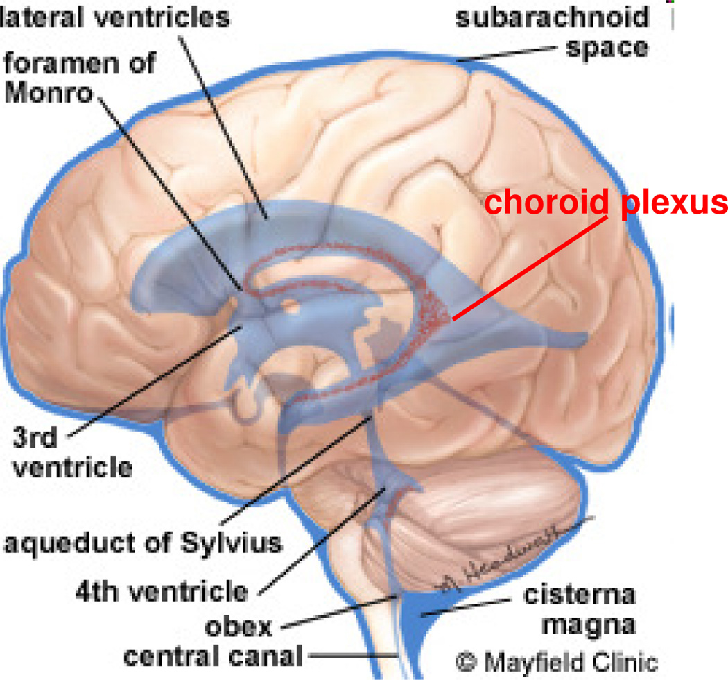
Cerebrospinal fluid (CSF) is a clear, watery fluid formed by choroid plexus that surrounds the brain and spinal cord and fills the ventricles, open spaces within the brain (Fig. 1). Hydrocephalus is a condition of altered CSF homeostasis, resulting in an abnormal accumulation of CSF in the brain ventricles. Approximately 69,000 people are diagnosed with hydrocephalus each year in the United States [6]. Untreated hydrocephalus leads to progressive neurological dysfunction and death.
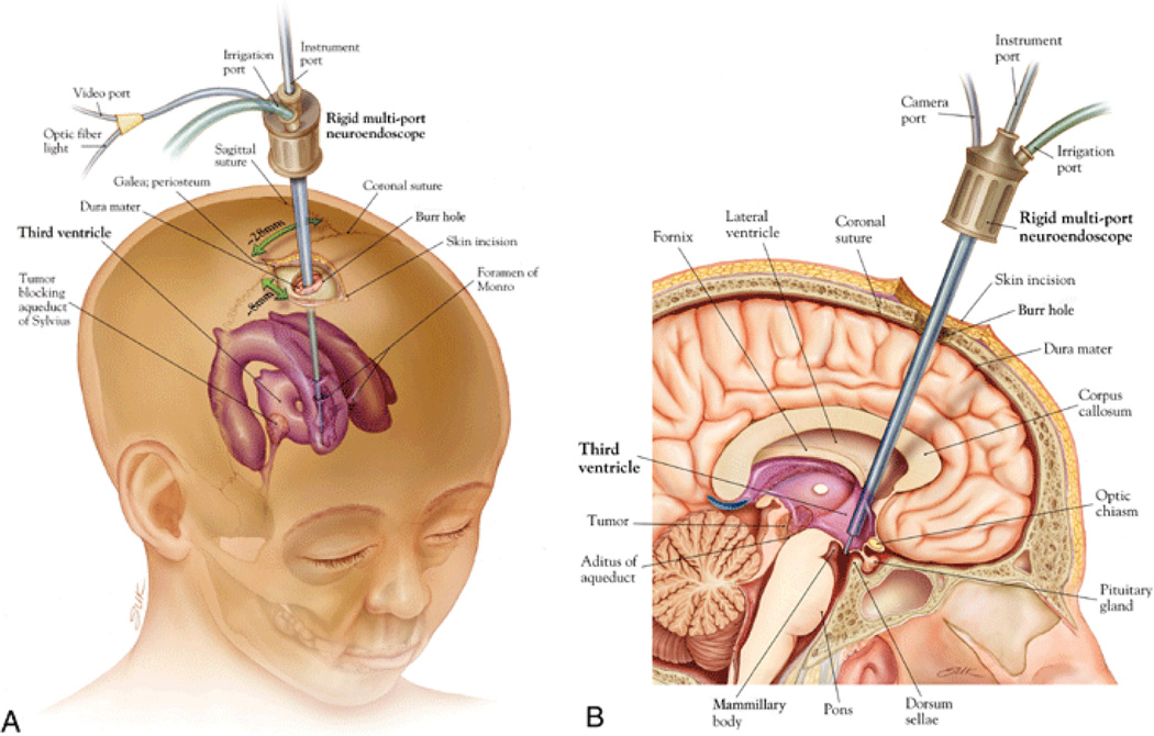
Endoscopic third ventriculostomy (ETV) is a surgical procedure which is used to treat certain forms of obstructive hydrocephalus, for example due to aqueductal stenosis, a narrowing of the duct connecting the third ventricle to the fourth ventricle called the aqueduct of Sylvius (Fig. 1). In ETV an opening is created in the floor of the third ventricle using an endoscope placed within the ventricular system (VS) through a burr hole in the skull (Fig. 2). This creates a natural bypass within the brain allowing the CSF to drain.
ETV is less effective in children under one year of age [7]–[9]. Warf and colleagues have demonstrated that combined ETV and choroid plexus cauterization (CPC) is significantly more effective than ETV alone in treating hydrocephalus without a shunt in this patient population [7], [5], [10]. In infants with hydrocephalus ETV alone was successful in only 35% of patients, compared to 76% success for the combined ETV/CPC procedure [7]. In a combined ETV/CPC procedure, after the ETV has been performed, attention is turned to the CPC: beginning at the foramen of Monro and gradually moving posteriorly, the choroid plexus of the lateral ventricle is thoroughly cauterized using the Bugby wire and low-voltage monopolar coagulating current.
Concentric tube robots are ideally suited for performing complex tasks as outlined above and required in minimally invasive neurosurgery: they possess cross sections comparable to needles and catheters, but are capable of substantial actively-controlled lateral motion and force application along their entire length. Since robot shape can be controlled, they enable navigation through the body along 3D curves. Furthermore, the lumen of the tubes can house additional tubes and wires for controlling articulated tip-mounted tools.
An example is shown in Fig. 3. The level of stiffness of the tubes is selected such that each telescoping section dominates all those sections extending from it. The result is that the shape and displacement of each telescoping section is kinematically decoupled from that of the proximal sections. In addition, each telescoping section is designed to have either fixed or variable curvature. A fixed curvature section relaxes to the shape of its pre-curvature when it is extended from the preceding section. In contrast, a variable curvature section can take on a continuous array of curvatures usually ranging between zero (straight) and a maximum value. A single tube is required to construct a constant curvature section while two tubes are needed to construct a variable curvature section. See [11] for a detailed description of how variable and constant curvature sections are constructed.
Fig. 3.
Concentric tube robot comprised of four telescoping sections that can be rotated and translated with respect to each other.
In the last few years, substantial progress has been made in developing concentric tube robotic technology [11]–[18]. Mechanics models have been developed for computing the kinematics [11], [12] and deformation due to external loading [14], [15]. Solution of the anatomically-constrained inverse kinematic problem has previously been considered [19], [20]. Real-time implementations of position control [11], [13] and stiffness control [17], [18] have been demonstrated in the laboratory and in beating-heart intracardiac animal trials. A topic that has received little attention is how to design concentric tube robots to meet the constraints imposed by a specific surgical task and anatomical environment. This is not surprising given the modeling complexity of these robots. In contrast to standard robots possessing rigid links and discrete joints, concentric tube robots are continuum robots. When their constituent pre-curved tubes are inserted inside each other, their common axis conforms to a mutual resultant curvature. By controlling relative translations and rotations of the tubes at their proximal ends, the shape and length of the robot can be varied. Thus, the tubes act as both links and flexure joints.
The contribution of this paper is the development of a new approach to optimal design of concentric tube robots targeted at applications in neurosurgery. This paper is organized as follows. In section II we present a technique for generating patient-specific geometric models of VS from medical images and summarize general assumptions. In section III we introduce a new parameterization particularly suited for a given optimization strategy. In section IV we formulate a problem of reaching a single target point in a confined space as a constrained optimization problem. In section V we extend this optimization approach to a generalized algorithm for finding a robot capable of reaching multiple target points within the confined space. In section VI we present four clinically relevant examples the algorithms. We summarize our results in section VII.
II. Geometric Model Generation
To apply our planning algorithm to neurosurgical problems, we assume that the robot will be introduced into the CSF space of the lateral cerebral ventricle using a straight introducer passing through a burr hole in the frontal bone of the skull (see Fig. 2). We assume that the robot is free to navigate within the ventricular space but must avoid touching the delicate lining of the ventricular wall. For a typical ETV/CPC procedure, the objectives are as follows: 1) to create a hole at the floor of the third ventricle and 2) to reach successive target points representing the location of the choroid plexus and apply radiofrequency energy to coagulate this highly vascular tissue.
Fig. 2.
ETV procedure. Oblique view (A) demonstrating typical location of the burr hole and trajectory; midsagittal view (B) demonstrating location of ventriculostomy. Source: Neurosug Focus ©.
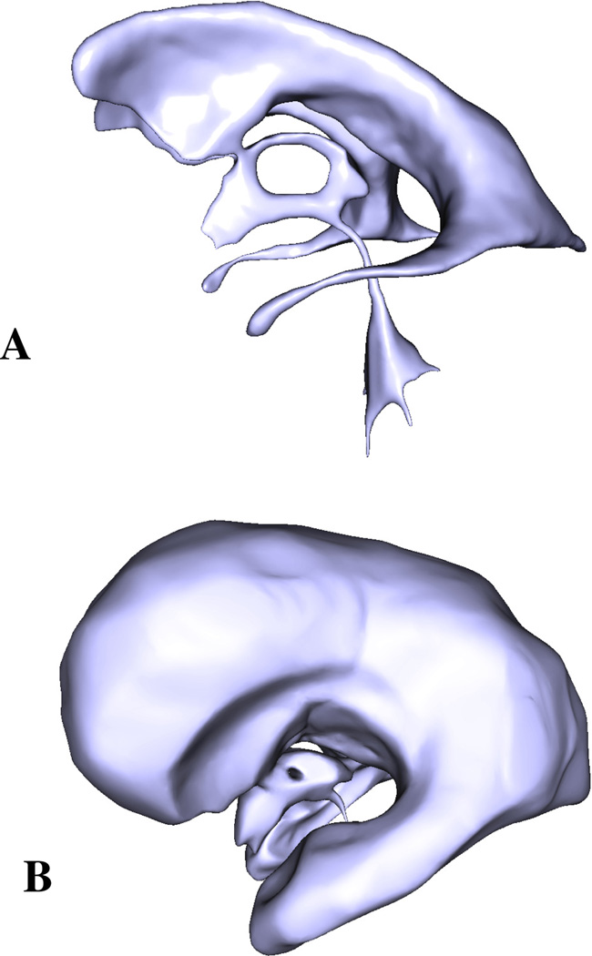
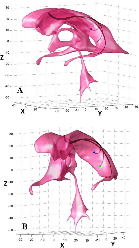
Cerebrospinal fluid, and to some extent the choroid plexus floating in it, can be reliably visualized with magnetic resonance (MR) imaging using T1- and T2-weighted sequences. These high-resolution image stacks can then be used to produce high fidelity models of the ventricular system. This technique involves semi-automatic segmentation of the CSF spaces in the VS, generation of a surface representing its boundary, and finally smoothing of the acquired surface using a Laplacian smoother. Using this approach we reconstructed a complete VS of a normal subject (Fig. 4A) and lateral and third ventricles of a hydrocephalic patient (Fig. 4B). The VS models are represented by triangular meshes and can be easily imported into Matlab (The MathWorks Inc., Natick, MA). We assume that the produced surfaces are closed and non-intersecting.
Fig. 4.
Geometric models of the VS of healthy (A) and hydrocephalic (B) subjects. The models were reconstructed from T1-weighted MR images.
III. Parametrization
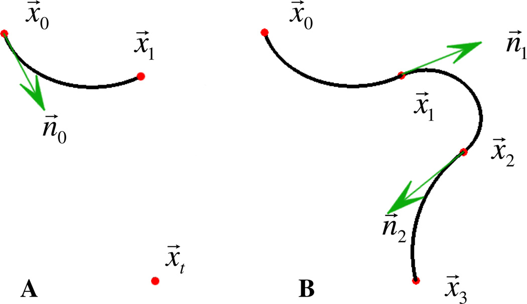
For simplicity, we represent tube sections by their respective centerlines (circular arcs) as shown in Fig 5. The circular sections are labeled with subscript indices i= 1,2, …, N. For a section i, the radius of curvature and the arc length are defined as Ri and li respectively, whereas θi is the rotation angle of section i + 1 with respect to section i. As mentioned above, for practical neurosurgical applications, parameters such as the entry point x⃗0 and the entry direction n⃗0, as well as the target point x⃗t, are generally predefined. Starting from the entry point we can arbitrarily select the end-point of the first section x⃗1 (Fig. 5A). For a given x⃗1, which can be moved freely in space, there exists only one circular arc passing through it, so by fixing the location of x⃗1 we fully define the first section in space x⃗1 (Fig. 5A). Similarly, for the next section the start-point x⃗1, as well as the direction n⃗1, are now constrained so that fixing x⃗2 in space leads to the full definition of the second section (Fig. 5B). We can recursively proceed in this fashion and introduce as many sections as needed with the last section’s end-point set at x⃗N = x⃗t (Fig. 5B). In summary, specifying the points x⃗1, …, x⃗N−1 allows us to define a unique N-sectioned robot. For each section it is then trivial to compute any other set of the kinematic variables for each individual section, such as the radii of curvature R1, …, RN, the curve lengths l1, …, lN and the angles of rotation θ1, …, θN−1. A similar approach, in which one computes section end-points for a given final section endpoint, has been shown to greatly reduce the complexity of the multisection inverse kinematics problem [22].
Fig. 5.
Parameterization definition: we assume that the entry and exit points x⃗0 and x⃗ t, as well as the direction n⃗0 are defined. For any arbitrarily selected x⃗1 there exists only one circular arc passing through it, so by fixing the location of x⃗1 we fully define the first section (A). Since specifying x⃗i also defines the direction n⃗i for the next section x⃗i + 1, we can recursively specify points x⃗1, …, x⃗N−1, with x⃗N = x⃗t and thus fully define a unique N- sectioned robot (B).
IV. Solution for a Single Target Point
The parameterization introduced in the previous section allows us to define families of robots with different numbers of sections by simply varying the locations of section endpoints x⃗1, …, x⃗N−1. If we now consider the problem of reaching a single target point in a confined space, it is always possible to find a robot configuration capable of doing just that, provided there are a sufficient number of sections. Finding a robot configuration with a minimal number of sections constitutes an optimization problem where the objective is to confine the robot within the anatomically defined boundaries of the VS.
Specifically, we define a function f1 which for a given robot configuration x⃗1, …, x⃗N−1 returns a relative percentage of a robot residing outside the VS surface T as follows:
| (1) |
where loutside is the total length of the subset of the robot remaining outside the surface and is the total length of the robot. For f1 = 0 the robot is confined within the surface.
In cases with less restrictive surface geometries where multiple solutions are expected to exist, it makes sense to restrict the total length of the robot and thus avoid unnecessary looping or coiling of the robot. In order to achieve this, we define another term:
| (2) |
where α is a scaling parameter that ensures f2 < 1. Accordingly, the cost function is the sum of the two terms:
| (3) |
We are now ready to define an algorithm as follows:
Algorithm 1
Set N = 2
- Compute
-
If f1 > 0
Set N = N + 1 and go to 2
Else stop
By tuning the cost function and adding additional terms, it is possible to control the design parameters of the robot, such as radii of curvature and arc lengths. These additional “soft” constraints are used to penalize tight turns or sections that are very short. For example, if one wishes to specify arbitrary radii of curvature R̅1, …, R̅N, the cost function in this case becomes:
| (4) |
where we introduce a new term
| (5) |
with the weightings for the individual sections βi. To ensure boundedness of f3, the weightings are scaled so that .
In some cases it may be desirable to control the direction at the tip of the robot, which can be achieved in a similar fashion by adding an appropriate penalty term to the cost function.
V. Solution for Multiple Target Points
In most cases, a more realistic set of tasks for a surgical robot to undertake would include targeting multiple points or tracing a curve or a surface in a three dimensional (3D) workspace. For such cases the design goal is to identify the least complex robot (with a minimal number of sections) that can perform a given task or set of tasks. This defines a new optimization problem where we aim to find a minimal number of sections N, for which the set of radii of curvature for each individual target point converges to the same set R̅1, …, R̅N. To achieve this goal we use Algorithm 1 with the cost function (3) for the first target point, and then for the rest of the target points we use Algorithm 1 with the cost function (4), which includes a “soft” constraint (5) that prefers solutions closest to the radii of curvature found in the solution to the first target point. Our experience has shown that the target point that is furthest from the entry point is usually the most difficult to reach, and is a good choice for the first target point.
We now extend the algorithms presented in the previous section for cases with multiple target points. In this algorithm we use the following notation: is the computed radius of curvature for a section i = 1, … N and a target point k = 1, … M. We assume that the target points are successively numbered, with 1 being the furthermost and M being the closet point with respect to the entry point.
Algorithm 2:
Find a minimal number of sections N for the first target point (k = 1) using Algorithm 1 with the cost function (3).
Compute radii of curvature for the solution in 1, and set .
Using Algorithm 1 with the cost function (4), find solutions with constraints on the radii of curvature to be as close as possible to R̅1, …, R̅N.
Given a set of solutions for all target points, compute (i) mean and (ii) a normalized standard deviation of radii of curvature among all the sections.
-
If ∑ Si > Sthr
If ∑ | R̂i − R̅i | > Rthr
Set R̅i = R̂i, i = 1, …, N and go to 3
Else
Set N = N + 1 and go to 2
Else stop
In step 5 there are two nested “if” statements. The outer “if” statement checks the standard deviation of the radii of curvature among all the sections for all target points: if the value is less than a threshold Sthr then the algorithm has found a viable solution. If the distribution is too wide the approach we take is to impose convergence to the mean of this distribution. If the algorithm converges to a solution (i.e. the relative change with respect to previous iteration is less than a threshold Rthr), but the distribution is still higher than the threshold Sthr, there are two possible solutions. The first solution is to increase the number of sections N (this solution is implemented in the inner “if” statement). The second solution is to set the section with highest normalized deviation Si as a variable curve section. In order to implement this, we relax the relative weighting βi in (4) for this particular section with respect to other sections thus allowing other sections to converge on the “expense” of the variable-curvature section. These alternative solutions lead to two different types of robots: (i) comprised of only fixed-curvature sections and (ii) comprised of one or more variable-curvature sections.
VI. Numerical Simulations
Here we present four clinically relevant examples. The entry points and direction in all examples were selected to match as closely as possible to an ETV procedure: the former is defined by the need to avoid damaging motor areas in the brain while the latter is defined by targeting an anatomically specified spot at the floor of the third ventricle. Minimizations of objective functions were performed using a Pattern Search (PS) algorithm [21] available in Matlab’s Global Optimization toolbox. PS is a member of a family of optimization methods called Direct Search methods. Direct Search methods are designed to search a set of points around the current point, looking for a point that has less objective value than the current one has. Since the underlying problem is highly nonlinear, selecting a good starting point is preferred from both the computational efficiency standpoint as well as for avoiding erroneous results. To aid in the selection of a good initial guess, we have developed a graphical user interface (GUI) in Matlab allowing the user to load a geometric model of the surface, select suitable start and end points with directions, add other constraints as needed, select the number of sections, and move the points x⃗1, …, x⃗N−1 freely in space. The GUI updates the robot configuration and highlights parts of the robot traversing the geometric model into the brain. After the initial configuration and the set of constraints have been specified, the user runs one of the algorithms outlined above.
A. Example 1 – Single target point
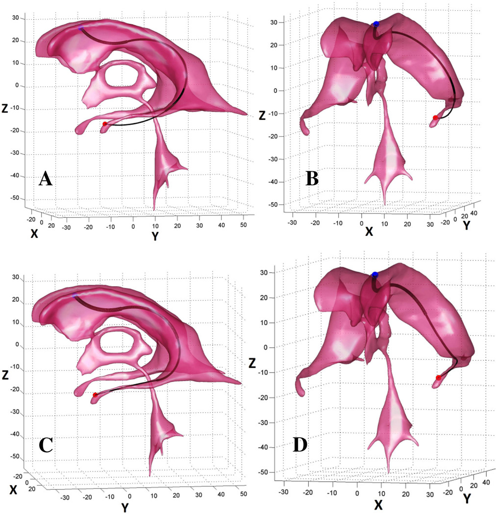
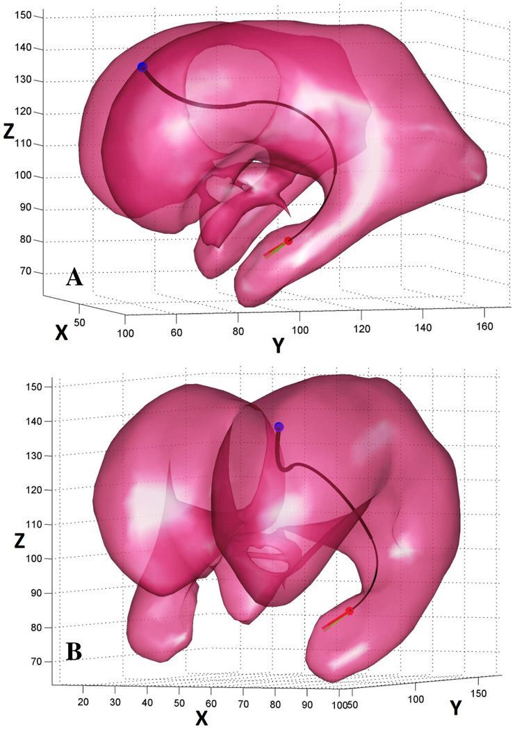
In this example, the objective is to navigate through a torturous geometry of the normal ventricular system to the tip of the temporal horn of the lateral ventricle. For the best solution found by Algorithm 1 for a three (N = 3) sectioned robot, only 83% of the robot was contained within the ventricle (Fig 6A, B). After setting N = 4, the algorithm converged to a solution where a robot is wholly contained within the ventricle (Fig 6C, D).
Fig. 6.
Example 1: the objective is to navigate from the entry point (blue dot) to the target point at tip of the temporal horn of the lateral ventricle (red dot). For a family of three sectioned robots, only up to 83% of the robot can be contained within the ventricle (A, B); the algorithm found a solution for a robot with four sections where the robot is wholly contained within the ventricle (C, D).
B. Example 2 – Single target point with a directional constraint
In this example the objective is to navigate inside the VS of a hydrocephalic ventricle and to approach the base of the choroid plexus from a predefined direction specified by the vector v⃗ = (−0.707,−0.707,−0.707) represented by a green arrow in Fig 7. For this task we employed a modified version of Algorithm 1 (with appropriate constraint on the direction at the tip of the robot f3 = β(1 − υ⃗ · n⃗N), where β is a weighting scalar and · is the dot product operator). The algorithm converged to a three sectioned robot with its tip tangent at n⃗3 = (−0.61,−0.62,−0.5), represented by a red arrow in Fig 7.
Fig. 7.
Example 2 - the objective is to navigate inside the VS of a hydrocephalic ventricle and to approach the base of the choroid plexus (red dot) from a predefined direction specified by the green vector. The algorithm succeeded in identifying a three sectioned robot with its tip direction aligned almost perfectly (red arrow) with the green arrow.
C. Example 3 – Multiple target points
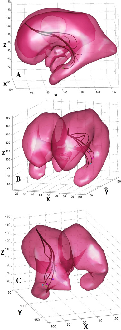
In this example the objective is to reproduce an ETV/CPC procedure: to navigate inside the ventricular system of a hydrocephalic brain and to trace the choroid plexus tissue with the tip of the robot and coagulate it. Based on MR images, we first identified coordinates of six target points along a virtual trajectory that would enable for effective coagulation of choroid plexus. Now the objective narrows down to finding a single robot configuration capable of reaching all the target points (i.e. ) so that the number of sections is minimal.
For solving this problem we employed Algorithm 2 with the following parameters: Sthr = 2E − 3, Rthr = 1E − 6. The algorithm converged to a solution with N = 3 fixed-curvature segments (Fig 8). Radii of curvature and section lengths for this solution are summarized in Table I.
Fig. 8.
Example 3 – the objective is to identify a single robot with minimal number of segments capable of reaching all six target points. A robot with only three segments was found by the algorithm. The design parameters for this robot are listed in Table I.
TABLE I.
Example 3: Section Radii of Curvature and Lengths
| Target Point |
R1 | R2 | R3 | l1 | l2 | l3 |
|---|---|---|---|---|---|---|
| 1 | 35.25 | 39.16 | 9.97 | 27.79 | 53.59 | 22.31 |
| 2 | 35.7 | 39.16 | 9.97 | 26.67 | 51.02 | 15.71 |
| 3 | 35.25 | 39.16 | 9.97 | 27.28 | 46.83 | 15.28 |
| 4 | 35.25 | 39.16 | 9.97 | 26.17 | 42.08 | 19.02 |
| 5 | 35.23 | 39.16 | 9.97 | 32.64 | 27.79 | 28.4 |
| 6 | 34.14 | 39.16 | 10.04 | 39 | 9.04 | 30.85 |
Example 3: Radii of curvature (in mm) and section lengths (in mm) computed by Algorithm 2 for all six target points. Note a very small deviation in the values of radii of curvature for the three (fixed-curvature) segments among all target points.
D. Example 4 – Multiple target points
Similar to the previous example, the objective is to find a robot configuration with the minimal number of sections capable of navigating inside the normal ventricular system and reaching all three target points. We again employed Algorithm 2 with the same threshold parameters. The algorithm converged to a solution with two fixed-curvature segments and one variable curvature segment (Fig 9). Radii of curvature and section lengths for this solution are summarized in Table II.
Fig. 9.
Example 4 – the objective is to identify a single robot with minimal number of segments capable of reaching all three target points. A robot with three (two constant- and one variable- curvature) segments was found by the algorithm. The design parameters for this robot are listed in Table II.
TABLE II.
Example 4: Section Radii of Curvature and Lengths
| Target Point |
R1 | R2 | R3 | l1 | l2 | l3 |
|---|---|---|---|---|---|---|
| 1 | 14.26 | 26.56 | 11.44 | 20.35 | 44.79 | 22.65 |
| 2 | 14.26 | 26.56 | 10.84 | 22.26 | 26.01 | 21.48 |
| 3 | 14.26 | 26.56 | 4.25 | 22.26 | 26 | 13.99 |
Example 4: Radii of curvature (in mm) and section lengths (in mm) computed by Algorithm 2 for all three target points. Note a very small deviation in the values of radii of curvature for the first two (fixed-curvature) segments and large deviation in the last (variable-curvature) segment.
VII. Conclusion
In this paper we outlined a novel approach to optimal design of concentric tube robots for applications in neurosurgery. A novel parameterization method was described and integrated into an optimization loop using cost functions and a global pattern search minimization routine. The formulation was tuned to generate the least complex robot (in terms of numbers of sections) capable of reaching a single target point. We then demonstrated how to implement various constraints on robot design by adding additional terms to cost function. Subsequently, we extended the algorithm to consider multiple targets in a confined space. Finally, we demonstrated the performance of these algorithms in four clinically relevant examples. The algorithms typically converge in less than five minutes for problems involving a single target point on a standard PC. For more complex problems involving multiple targets, this time is multiplied by the number of target points and the number of outer loop iterations in Algorithm 2. Moderately complex problems with multiple targets such as Examples 3 and 4 converge within two to three hours. The most computationally expensive step is the evaluation of the function f1, namely finding if the current robot configuration violates the VS anatomy. Naturally, the computational time may be reduced by decreasing the resolution of the surface representing the anatomy, so it is beneficial to find maximal resolution that allows for appropriate representation of important anatomical structures.
While the approach developed here permits design of a robot to accomplish coagulation of the choroid plexus, the ability to perform coordinated movements within a constrained space in the brain could be used to reach and remove tumors, vascular anomalies, seizure foci, and other targets. As with current endoscopic techniques using handheld flexible devices, many options would be available for visualization and tissue ablation or manipulation. Indeed, navigation within CSF would also be possible within the spinal CSF space and other body cavities. On-demand assembly of an endoscopic device optimized for a particular patient or situation from available components would be possible. Better clinical outcomes should follow improved technologies merging imaging and robotics.
Fig. 1.
Ventricular system (VS) of the brain consists of four cerebral ventricles: the paired lateral ventricles, and the midline third and fourth ventricles. Source: Mayfield Clinic ©.
Acknowledgments
T.A and J.R.M were supported by the National Institutes of Health under grant 5R44RR020247, by the US Army (DoD) under the grant W81XWH-05-C-0166, and by the Webster family. P. D. was supported by the National Institutes of Health under grants R01HL073647 and R01HL087797.
Contributor Information
Tomer Anor, Department of Neurosurgery, Children’s Hospital Boston, Harvard Medical School, Boston, MA 02115 USA (Tomer.Anor@childrens.harvard.edu).
Joseph R. Madsen, Department of Neurosurgery, Children’s Hospital Boston, Harvard Medical School, Boston, MA 02115 USA (Joseph.Madsen@childrens.harvard.edu).
Pierre Dupont, Cardiovascular Surgery, Children’s Hospital Boston, Harvard Medical School, Boston, MA 02115 (Pierre.Dupont@childrens.harvard.edu).
References
- 1.Dimaio SP, Archip N, Hata N, Talos IF, Warfield SK, Majumdar A, Mcdannold N, Hynynen K, Morrison PR, Wells WM, 3rd, Kacher DF, Ellis RF, Golby AJ, Black PM, Jolesz FA, Kikinis R. Image-guided neurosurgery at Brigham and Women's Hospital. IEEE Eng Med Biol Mag. 2006 Sep–Oct;25(5):67–73. doi: 10.1109/memb.2006.1705749. [DOI] [PubMed] [Google Scholar]
- 2.Hall WA, Truwit CL. Intraoperative MR-guided neurosurgery. Neurosurgery. 2008 Jun;62(6) Suppl 3:1555–1579. discussion 1579–82. [Google Scholar]
- 3.Elder JB, Hoh DJ, Oh BC, Heller AC, Liu CY, Apuzzo ML. The future of cerebral surgery: a kaleidoscope of opportunities. Neurosurgery. 2008 Jun;62(6) Suppl 3:1555–1579. doi: 10.1227/01.neu.0000333820.33143.0d. discussion 1579–82. [DOI] [PubMed] [Google Scholar]
- 4.Eljamel MS. Robotic neurological surgery applications: accuracy and consistency or pure fantasy? Stereotactic Funct .Neurosurg. 2009;87(2):88–93. doi: 10.1159/000202974. [DOI] [PubMed] [Google Scholar]
- 5.Warf BC. Endoscopic third ventriculostomy and choroid plexus cauterization for pediatric hydrocephalus. Clin Neurosurg. 2007;54:78–82. [PubMed] [Google Scholar]
- 6.Bondurant CP, Jimenez DF. Epidemiology of cerebrospinal fluid shunting. Pediatr Neurosurg. 1995;23:254–258. doi: 10.1159/000120968. discussion 259. [DOI] [PubMed] [Google Scholar]
- 7.Warf BC. Hydrocephalus in Uganda: the predominance of infectious origin and primary management with endoscopic third ventriculostomy. J Neurosurg. 2005;102:1–15. doi: 10.3171/ped.2005.102.1.0001. [DOI] [PubMed] [Google Scholar]
- 8.Warf BC. Comparison of endoscopic third ventriculostomy alone and combined with choroid plexus cauterization in infants younger than 1 year of age: a prospective study in 550 African children. J Neurosurg. 2005;103:475–481. doi: 10.3171/ped.2005.103.6.0475. [DOI] [PubMed] [Google Scholar]
- 9.Warf BC, Mugamba J, Kulkarni AV. Endoscopic third ventriculostomy in the treatment of childhood hydrocephalus in Uganda: report of a scoring system that predicts success. J Neurosurg Pediatr. 5:143–148. doi: 10.3171/2009.9.PEDS09196. YEAR. [DOI] [PubMed] [Google Scholar]
- 10.Warf BC. Endoscopic coagulation of the choroid plexus in the management of hydrocephalus in developing countries. In, "Endoscopy and its application to ventricular lesions". 30th Anniversary Supplement to Neurosurgery: "Surgery of the Cerebrum", Part II. 2008;103:583–584. [Google Scholar]
- 11.Dupont P, Lock J, Itkowitz B, Butler E. Design and Control of Concentric Tube Robots. IEEE Trans Robotics. 2010;26(2):209–225. doi: 10.1109/TRO.2009.2035740. [DOI] [PMC free article] [PubMed] [Google Scholar]
- 12.Rucker D, Webster R, III, Chirikjian G, Cowan N. “Equilibrium Conformations of Concentric-tube Continuum Robots,”. Int J Robotics Research. 2010 doi: 10.1177/0278364910367543. [DOI] [PMC free article] [PubMed] [Google Scholar]
- 13.Dupont P, Lock J, Itkowitz B. Real-time Position Control of Concentric Tube Robots; IEEE Int Conf Robotics and Automation; 2010. pp. 562–568. [DOI] [PMC free article] [PubMed] [Google Scholar]
- 14.Rucker DC, Jones BA, Webster RJ., III A Model for Concentric Tube Continuum Robots Under Applied Wrenches; IEEE Int Conf Robotics and Automation; 2010. pp. 1047–1052. [DOI] [PMC free article] [PubMed] [Google Scholar]
- 15.Lock J, Laing G, Mahvash M, Dupont P. Quasistatic Modeling of Concentric Tube Robots with External Loads. IEEE/RSJ Intelligent Robots and Systems (IROS) 2010 doi: 10.1109/IROS.2010.5651240. in press. [DOI] [PMC free article] [PubMed] [Google Scholar]
- 16.Dupont P, Lock J, Itkowitz B. Real-time Position Control of Concentric Tube Robots; Conf Proc IEEE International Conference on Robotics and Automation; 2010. pp. 562–568. [DOI] [PMC free article] [PubMed] [Google Scholar]
- 17.Mahvash M, Dupont P. Stiffness Control of a Continuum Manipulator in Contact with a Soft Environment; IEEE/RSJ Int Conf Intelligent Robots and Systems; Taipei, Taiwan: 2010. [DOI] [PMC free article] [PubMed] [Google Scholar]
- 18.Mahvash M, Dupont P. Stiffness Control of Continuum Surgical Manipulators. IEEE Trans. Robotics. 2010 doi: 10.1109/TRO.2011.2105410. in press. [DOI] [PMC free article] [PubMed] [Google Scholar]
- 19.Lyons L, Webster R, III, Alterovitz R. Motion Planning for Active Cannulas. IEEE/RSJ Int; Conference on Intelligent Robots and Systems; St. Louis. 2009. pp. 801–806. [Google Scholar]
- 20.Lyons L, Webster R, III, Alterovitz R. Planning Active Cannula Configurations through Tubular Anatomy; IEEE Int Conf Robotics and Automation, Anchorage; 2010. pp. 2082–2087. [Google Scholar]
- 21.Charles Audet, Dennis JE., Jr Analysis of Generalized Pattern Searches. SIAM Journal on Optimization. 2003;Volume 13(Number 3):889–903. [Google Scholar]
- 22.Neppalli S, Csencsits M, Jones B, Walker ID. A Geometrical Approach to Inverse Kinematics for Continuum Manipulators. IROS. 2008 [Google Scholar]


