Abstract
As a treatment for aortic stenosis, several companies have recently introduced prosthetic heart valves designed to be deployed through a catheter using an intravenous or trans-apical approach. This procedure can either take the place of open heart surgery with some of the devices, or delay it with others. Real-time 3D ultrasound could enable continuous monitoring of these structures before, during and after deployment. We have developed a 2D ring array integrated with a 30 French catheter that is used for trans-apical prosthetic heart valve implantation. The transducer array was built using three 46 cm long flex circuits from MicroConnex (Snoqualmie, WA) which terminate in an interconnect that plugs directly into our system cable, thus no cable soldering is required. This transducer consists of 210 elements at .157 mm inter-element spacing and operates at 5 MHz. Average measured element bandwidth was 26% and average round-trip 50 Ohm insertion loss was -81.1 dB. The transducer were wrapped around the 1 cm diameter lumen of a heart valve deployment catheter. Prosthetic heart valve images were obtained in water tank studies.
Introduction
Aortic stenosis (AS), the incomplete opening of the aortic valve, is the most common form of valvular heart disease in the western world [1]. Typical treatment is surgical heart valve replacement or repair. However, about 30% of the population demonstrating severe symptoms for AS are denied surgery based on age or other pre-existing conditions [2,3]. Aortic valvuloplasty is a typical treatment for these patients. This procedure entails a balloon catheter being placed in the valve orifice and expanded to increase blood flow. It does not always provide a long term solution [4]. Several companies have recently introduced prosthetic heart valves that are implanted transapically or intravenously with a catheter deployment kit. The first procedure was performed on a human in 2002 [4]. Guidance of these procedures is done with fluoroscopy and transesophageal ultrasound (TEE) [5]. Real-time 3D ultrasound guidance of these procedures could reduce or eliminate the need for x-ray based fluoroscopy. In the case of transapically implanted prosthetic heart valves, we propose that a ring array transducer integrated into, and surrounding, the deployment catheter can enable continuous monitoring of both the tissue and the valve before, during, and after deployment. We have developed a ring transducer that can be attached to the distal end of a transapical deployment catheter to be used for real time 3D ultrasound guidance.
Methods: Transducer Design
Our transducer design is integrated with a commercial prototype of a trans-apical heart valve implantation kit. The transducer mounts on the head of the deployment catheter, which is 1 cm in diameter. For these first prototypes, we are taking advantage of two previous technologies which we used in catheter feasibility studies of real time 3D ultrasound guidance of vena cava filters and aortic aneurysm stent grafts. The first is to use previously fabricated flexible circuits to connect to our transducer elements [6]. The second is to use an already existing system cable to interconnect our transducer to the real-time 3D ultrasound scanner (Volumetrics, Inc. Durham, NC) [10]. The interconnect consists of 7 double sided low insertion force connectors (Tyco Electronics, Portland, OR) at the transducer end which mate with our single sided flex circuit. Each connector has 72 possible connections. The scanner has 256 shared transmit/receive channels, and 256 transmit only channels. However, the handle was designed for an earlier generation of our system, and has only 440 independent connections. Another complication is that the shared connections (transmit/receive) and transmit only connections are interspersed throughout the 440 possible sites. Due to this configuration, our transducer will consist of a transmit aperture of 208 elements and a receive aperture of 176 elements.
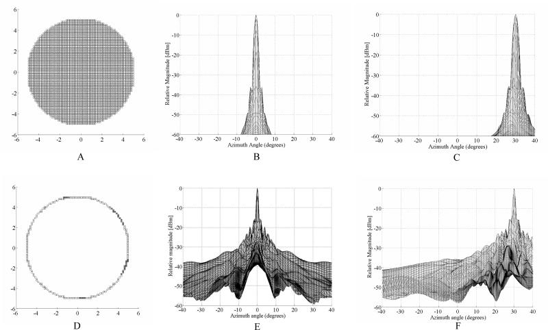
We ran Field II [7] simulations for a gold standard fully sampled aperture of 3348 elements versus our proposed ring array. For both simulations, we approximated the circular aperture using rectilinear sampling corresponding to the cuts of our dicing saw. The interelement spacing was 0.157 mm. All the simulations were run without apodization at 5 MHz with a 30% fractional bandwidth and transmit and receive focus at 50 mm over an angular range of +/- 40°. The fully sampled aperture is shown in Figure 1A. Figure 1B shows the on axis simulation result with the first sidelobe level at –37 dB and +/- 3.3°. Figure 1C shows the case where we steered the beam to 30° in both azimuth and elevation. Figure 1D shows the simulated ring array aperture. The filled gray elements represent the transmit only elements. The on axis response is shown in figure 1E. The inner side lobes have a relative magnitude of -15.8 dB at +/- 1.5°, and the outer side lobes are -20 dB at +/- 4°. Figure 1F shows the simulations when the transmit and receive beams are steered to 30° in both azimuth and elevation. Again, the focus is at 50 mm. With an interelement spacing of nearly half lambda, we do not expect to see a grating lobe at these steering angles.
Figure 1.
Field II simulations showing the fully populated 10 mm diameter control aperture (A) and resulting on-axis (B) and 30° off axis (C) plots. The beam in (C) was steered to 30° in both azimuth and elevation. From figure 1B , the nearest side lobe level is –37dB at +/- 3.3°. Figure 2D shows our simulated ring aperture of the same diameter. The filled gray elements in E represent transmit only elements. Figure 1E shows the on axis response for the aperture in 2D with the nearest side lobe level is –15.8 dB and +/- 1.5°. Figure 1F shows the response from the aperture in 2D after steering the beam to 30° in both azimuth and elevation.
Transducer Fabrication
We began with three 46-cm long, 11 cm wide flexible circuits (flexes) from MicroConnex (Snoqualmie, WA). These flexes are composed of a base layer of .025 mm thick polyimide upon which 70 parallel metal traces set at a center-to-center spacing of .157 mm are laid on one side. On the other side is a layer of copper. At one end, the traces stop short .280 mm from the edge of the polyimide, leaving a small shelf. The shelf has two .010 mm deep cuts spaced at .150 mm running perpendicular to the traces that serve to increase the surface area of the shelf. At the other end, the traces terminate with interconnects that plug directly into our system cable. We prepared beams of fine-grain PZT (TRS, State College, PA) that were .30 mm tall, .18 mm wide, and 12 mm long. We attached these beams to the shelves of the flexes using a low viscosity epoxy (Epo-Tek 301, Epoxy Technology, Billerica, MA) such that they just contacted the traces on one side, and hung off the shelf on the other side. The sides of the beam pointing forward and backward are electroded with gold. After the beams were attached, we applied a thin layer of silver paint to all of the traces and to the entire backward-facing electrode of the beam on each flex, creating an electrical connection between each trace and the beam. We then diced each transducer beam using a Disco DAD 3220 diamond-wheel dicing saw (Cary, NC) at .157 mm spacing, creating and electrically isolating 70 elements from each beam.
The flexes have to be attached to the deployment catheter with a nominal ID of .375” (9.525 mm), and a measured OD of 11.18 mm. However, due to a later step, they cannot be directly attached to the catheter. Instead, we had to fabricate a 2.5 cm long tube made of polyimide with an 11.18 mm ID. We used Hysol E-60NC epoxy potting compound to attach the flexes to the tube such that the faces of all the elements were coplanar at the edge of the tube. Two of the flexes were lined up edge to edge, with the third one attached such that it had a 1.25 mm gap between each of the other two. We then used the Hysol E-60NC (Loctite, Rocky Hill, CT) to fill the element kerfs. We applied a mixture of DER332/DEH24 (Dow Chemical Company, Midland, MI) epoxy, phenolic micro-balloons, and zeeospheres in a 25:2:4 weight ratio to the backs of all of the elements. Next, we wrapped a .012 mm thick strip of metalized liquid crystal polymer (LCP) around the elements and part of the traces, such that the edge of the LCP was flush with the faces of the transducer. We took the flexes attached to the polyimide tube and sputtered gold onto the faces of the elements and the LCP, electrically connecting them. We soldered wires from the LCP to the backs of the flexes, and from the backs of the flexes to the ground trace of the system cable interconnect, connecting all of the elements to a common ground. Finally, the entire transducer was wrapped with heat shrink tubing up to the face of the transducer. Loctite 366 UV (Loctite, Rocky Hill, CT) curing epoxy was applied to the face of the transducer, running down to the heat-shrink tubing in order to waterproof the device. Finally, we applied a 20:3 weight ratio mixture of Loctite 366 and phenolic micro-balloons to the inside of the tube beneath the elements and to the outside of the heat-shrink above the elements, forming concentric rings around the elements.
Transducer Measurement
We performed pulse-echo tests on the transducer in a water tank by pulsing and receiving on individual single elements using a Model 5073PR Pulser/Receiver (Panametrics Inc., Waltham, MA). The pulser was set for maximum amplitude, with a pulse repetition frequency of 500 Hz. The receiver was set for 39 dB of gain, and with a 20 MHz low pass filter. We used an aluminum block set at a depth of 1 cm as a reflector. We looked at the received pulses with a TDS744A oscilloscope (Tektronix, Inc., Beaverton, OR). We used a Panametrics Model 5605A Stepless Gate to gate the received pulses, and an HP3588A Spectrum Analyzer (Agilent Technologies, Inc., Santa Clara, CA) to look at the frequency response spectra. The pulses and spectra were downloaded to a Windows computer over a GPIB interface using Labview 2009 software.
We also measured the round-trip 50 ohm insertion loss in the water tank. To measure this, we used a Agilent 33250A function generator outputting a 6 cycle sine burst with a peak-to-peak amplitude of 170 mV, fed through a ENI 525LA 25W (E&I, Ltd., Rochester, NY) amplifier to increase the peak-to-peak voltage to 120 V, to excite a single element. We measured the received pulse on an adjacent element with the TDS744A oscilloscope. Both the amplifier and the oscilloscope were loaded with 50 Ohms. In order to minimize diffractive losses, the aluminum reflector was set at the shallowest depth possible outside of the ring down of the pulse, which was 3.2 mm away from the transducer face.
Real-time 3D scanning
We used standard three dimensional (3D) phased array beaming forming techniques to generate our real-time 3D images. Real time 3D ultrasound was developed in our laboratories at Duke University by von Ramm and Smith [8,9] and first commercialized for cardiovascular applications by Volumetrics Medical Imaging, Inc.(VMI, Durham, NC). The Duke/VMI 3D system scans a 65° – 120° pyramid with matrix array transducers of up to 500 active channels to produce 3D scans at rates up to 30 volumes/sec using 16:1 receive mode parallel processing. While the system allows for different transmit apertures as a function of depth to keep a constant f number, we did not utilize that option in this work. Real time display options include up to five image planes oriented at any desired angle, depth and thickness within the pyramidal scan as well as real time 3D volume rendering, 3D pulse wave Doppler and 3D color flow Doppler. In our laboratories at Duke during the last few years, we have significantly modified the Volumetrics scanner to use our prototype 2-D arrays for applications such as real time 3D transesophageal imaging [10], laparoscopic imaging [11], intracardiac and intravascular imaging with catheter transducers [12] at 5, 7, 10 [13] and 15 MHz [14]. No new modifications were needed for the transducers described in this paper to run on the VMI Model 1 scanner.
Results
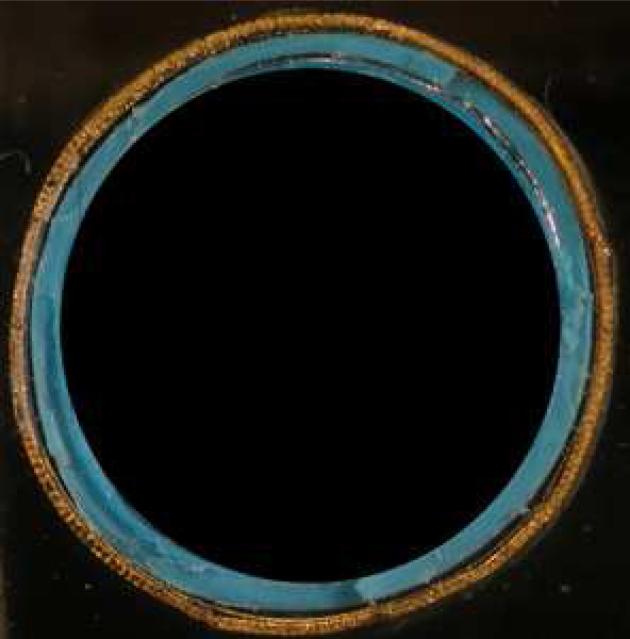
Figure 3 shows an end view of the completed transducer. Figure 4 shows a typical pulse and power spectrum of the transducer. The center frequency is 4.58 MHz and the -6 dB bandwidth is 21 % . The average -6 dB bandwidth for all elements of this transducer is 26%, with a standard deviation of .09%. The average center frequency is 4.61 MHz, with a standard deviation of .19 MHz. The average round-trip 50 ohm insertion loss is -81.1 dB, with a standard deviation of 2.7 dB.
Figure 3.
The completed transducer.
Figure 4.
Typical pulse echo response (A) and the corresponding frequency spectrum (B) of this transducer. The center Frequency is 4.58 MHz and the -6 dB bandwidth is 21%.
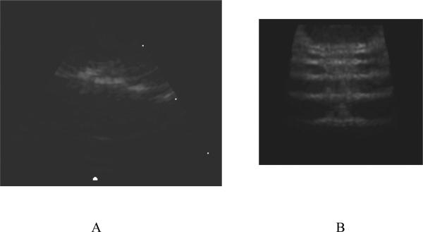
Figure 5 shows a B-mode image (fig. 5A) and a C-mode plane (fig. 5B) from a 3D scan of the lateral resolution wires of the AIUM wire phantom with the wires spaced at 1, 2, 3, 4 and 5 mm. While we can resolve each wire in the C-scan image, we can also see the effects of the side lobes predicted by our beam plot in fig. 4.
Figure 5.
A B-scan (A) and C-Scan (B) of the AIUM wire phantom. The wires are separated by 1, 2, 3, 4 and 5 mm.
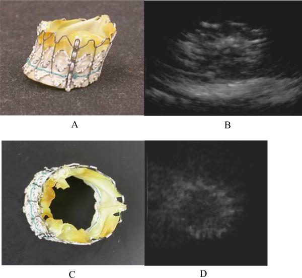
Figure 6 shows a photograph of a prosthetic heart valve in figures 6A and 6C. This valve is a prototype unit, and has been expanded and dried. Figures 6B and 6D show real-time 3D rendered images of the same prosthetic heart valve in a water bath on top of a piece of rubber. We can see some of the struts that make up the frame that holds the valve and the overall shape of the whole device in each image.
Figure 6.
A photograph of a prosthetic heart valve (A and C) and a real–time rendered ultrasound image of it in a water bath (B and D). The view in figures 6A and 6B are from the side. Figures 6C and 6D show an end view. The valve is resting on a piece of rubber in the ultrasound images.
Discussion
We were able to build a ring transducer larger than our previous catheters with 204 elements in transmit and 172 elements in receive. Figure 6 shows a typical pulse shape and bandwidth for unmatched ceramic elements. We encountered a long ring down from the transmit pulse while measuring the 50 Ohm insertion loss. This prevented us from getting the reflector closer to the face of the transducer than 3.2 mm. With such small elements, we have significant losses due to diffraction at this distance.
We were able to make real-time 3D images with the transducer in a water tank. However, when we imaged in tissue mimicking phantoms and in a sheep heart, we saw significant clutter. There was time dependent cutter which was especially bad near the top of the B-scans, as well as lateral clutter. We hypothesized that the time dependent clutter was due to reverberations within the catheter lumen, and added the micro-balloons which reduced this clutter. The balloons serve as an air interface and since we have them covering all sides of the elements except for the forward-view direction, all sound not moving forward generated by the elements would be immediately reflected back. In order to try to further reduce this time dependent clutter in future iterations of this device, we will integrate the phenolic micro-balloons into the epoxy that holds the flexes to the catheter so that they are much closer to the elements.
As we see from our simulations (figure 2), we have a high sidelobe level of –15.8 dB. This is the cause of the lateral clutter seen in our images. Other groups have suggested using a synthetic aperture technique to improve sidelobe levels [15,16]. If they can be implemented in real-time, these techniques will help improve image quality for ring array apertures. Since we plan to use these transducer for guidance of interventional procedures, they must be able to image at real-time volume rates.
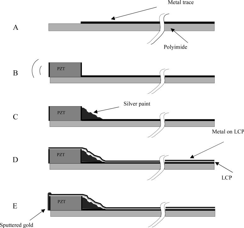
Figure 2.
A schematic of the steps to building the ring array transducers. We start with a metallized polyimide substrate (figure 2A) with an area without the metal to attach the PZT. We next attach the PZT beam (figure 2B) with non-conductive epoxy. After the epoxy cures, silver paint is used to connect the back electrode of the PZT with the metal trace (figure 2C). The PZT is then diced, and wrapped around a lumen. A 0.012 mm thick layer of liquid crystal polymer (LCP) is wrapped around the outer circumference of the PZT and polyimide substrate (figure 2D). This LCP layer is metallized with gold (shown in black) on one side only, the outer side, so that it does not risk shorting the traces together. A layer of gold is sputtered on the face of the elements and connected to the gold on the outside of the LCP (figure 2E).
While relatively easy to fabricate compared to a fully sampled 2D array aperture, ring array transducers have unusual physical characteristics that may require development of new materials. A typical 2D element is free to vibrate in its lateral dimensions. However, bonding to the rigid polyimide flex circuit, which is further bonded to the catheter lumen creates a very different lateral structure. The elements are also wrapped in the LCP layer. These layers lead to reverberations that cause time dependent clutter. New materials for the catheter lumen may need to be developed to fully control these issues.
References
- 1.Iung B, Baron G, Butchart E, et al. A prospective survey of patients with valvular heart disease in Europe: the Euro Heart Survey on valvular heart disease. Eur Heart J. 2003;24:1231–124. doi: 10.1016/s0195-668x(03)00201-x. [DOI] [PubMed] [Google Scholar]
- 2.Bach D, Siao D, Girard S, et al. Evaluation of patients with severe symptomatic aortic stenosis who do not undergo aortic valve replacement. Circ Cardiovasc Qual Outcomes. 2009;2:533–539. doi: 10.1161/CIRCOUTCOMES.109.848259. [DOI] [PubMed] [Google Scholar]
- 3.Iung B, Cachier A, Baron G, et al. Decision-making in elderly patients with severe aortic stenosis: why are so many denied surgery? Eur Heart J. 2005;26:2714–2720. doi: 10.1093/eurheartj/ehi471. [DOI] [PubMed] [Google Scholar]
- 4.Cribier A, Eltchaninoff H, Bash A, et al. Percutaneous transcatheter implantation of an aortic valve prosthesis for calcific aortic stenosis: first human case description. Circulation. 2002;106:3006–3008. doi: 10.1161/01.cir.0000047200.36165.b8. [DOI] [PubMed] [Google Scholar]
- 5.Himbert D, Descoutures F, Al-Attar N, et al. Results of transfemoral or transapical aortic valve implantation following a uniform assessment in high-risk patients with aortic stenosis. J. Am. Coll. Cardiol. 2009;54:303–311. doi: 10.1016/j.jacc.2009.04.032. [DOI] [PubMed] [Google Scholar]
- 6.Light E, Lieu V, Smith S. New Fabrication Techniques for Ring-array Transducers for Real-Time 3D Intravascular Ultrasound. Ultrasonic Imaging. 2009;31:247–256. doi: 10.1177/016173460903100403. [DOI] [PMC free article] [PubMed] [Google Scholar]
- 7.Jensen J, Svendsen N. Calculation of pressure fields from arbitrarily shaped, apodized, and excited ultra -sound transducers. IEEE Trans Ultrason Ferro Freq Con. 1992;39:262–267. doi: 10.1109/58.139123. [DOI] [PubMed] [Google Scholar]
- 8.Smith SW, Pavy HE, von Ramm OT. High speed ultrasound volumetric imaging system part I: transducer design and beam steering. IEEE Trans Ultrason Ferroelec Freq Contr. 1991;32:100–108. doi: 10.1109/58.68466. [DOI] [PubMed] [Google Scholar]
- 9.von Ramm OT, Smith SW, Pavy HE. High speed ultrasound volumetric imaging system part II: Parallel processing and display. IEEE Trans Ultrason Ferroelec Freq Contr. 1991;38:109–115. doi: 10.1109/58.68467. [DOI] [PubMed] [Google Scholar]
- 10.Pua EC, Idriss SF, Wolf PD, Smith SW. Real-time 3D transesophageal echocardiography. Ultrasonic Imaging. 2004;27:217–232. doi: 10.1177/016173460402600402. [DOI] [PubMed] [Google Scholar]
- 11.Light ED, Idriss SF, Sullivan KF, Wolf PD, Smith SW. Real-Time 3D Ultrasonic Laparoscopy. Ultrasonic Imaging. 2005;27:89–100. doi: 10.1177/016173460502700301. [DOI] [PubMed] [Google Scholar]
- 12.Lee W, Smith SW. Miniaturized catheter 2D for real-time 3D intracardiac echocardiography. IEEE Trans Ultrason Ferroelec Freq Contr. 2004;51:1334–1346. doi: 10.1109/tuffc.2004.1350962. [DOI] [PubMed] [Google Scholar]
- 13.Light ED, Smith SW. Two Dimensional Arrays for Real Time 3D Intravascular Ultrasound. Ultrasonic Imaging. 2004;26:115–128. doi: 10.1177/016173460402600204. [DOI] [PubMed] [Google Scholar]
- 14.Light ED, Smith SW. Two-Dimensional Arrays for Real-Time 3D Intra-luminal Ultrasound Imaging. 30th Symposium on Ultrasonic Imaging and Tissue Characterization; May, 2005. 2005. [Google Scholar]
- 15.Wang Y, Stephens DN, O'Donnell M. A forward-viewing ring-annular ultrasound array for intravascular imaging. Proc. IEEE Ultrason. Symp. 2001:1573–1576. doi: 10.1109/tuffc.2002.1159845. [DOI] [PubMed] [Google Scholar]
- 16.Yeh DT, Oralkan O, Wygant IO, O'Donnell M, Khuri-Yakub BT. 3-D ultrasound imaging using a forward-looking CMUT ring array for intravascular/intracardiac applications. Ultrasonics, Ferroelectrics and Frequency Control, IEEE Transactions on. 2006 June;53(6):1202–1211. doi: 10.1109/tuffc.2006.1642519. [DOI] [PubMed] [Google Scholar]


