Abstract
Three-dimensional ultrasound has been an effective imaging modality for diagnostics and is now an emerging modality for image-guided minimally-invasive interventions since it enables visualization of both instruments and tissue. Challenges to ultrasound-guided interventions arise, however, due to the low signal-to-noise ratio and the imaging artifacts created by the interventional instruments. Metallic instruments, in particular, are strong scatters and so produce a variety of artifacts. For many interventions, the manual or robotic instrument is comprised of a long curved tubular structure with specialized tooling at its tip. Toward the goal of developing a surgical navigation system, this paper proposes an image processing algorithm for enhancing the tubular structure of imaged instruments while also reducing imaging artifacts. Experiments are presented to evaluate the effectiveness of the approach in the context of robotic instruments whose shape comprises a smooth curve along their length.
I. Introduction
The last decade has led to substantial progress in three-dimensional medical imaging techniques including CT, MRI, and ultrasonography. MRI and CT usually produce higher quality volumetric images than ultrasound. Compared with MRI and CT, however, ultrasound imaging has a number of advantages, including affordability, portability, speed and safety of use for both patient and clinician. Consequently, there has been substantial interest in applying real-time 3D ultrasound to image-guided minimally-invasive interventions [1], [2], [3], [4].
An existing impediment to the use of 3D ultrasound in these applications, however, is the difficulty of recognizing objects from the volumetric images, particularly for the automatic detection of instruments. A number of researchers have developed algorithms for instrument navigation during interventional procedures. For example, ultrasound based tracking problems have been investigated for instruments consisting of a straight shaft in intracardiac surgery [2], [3], [4], liver biopsies [5], prostate brachytherapy [6], ex-vivo phantom experiments [7], and concentric tube robots in cardiac surgery [8], [9]. There are also studies for tracking needles, catheters or surgical grippers in 2D ultrasound images [10], and recently on tracking the shaft of instruments [7], [2], [3], [5] using 3D ultrasound. Most of this work has focused on development of the tracking algorithms and there are few details on artifact reduction except for well-addressed speckle artifact reduction algorithms.
In instrument imaging, artifacts can produce a variety of shapes and patterns that change according to the instrument's position and orientation in the image. These artifacts not only obscure the shape and location of the instrument, they also obscure nearby tissue making it difficult to visualize tool-tissue interaction. Therefore, artifact reduction and instrument structure enhancement are essential steps for improving instrument visualization for both manual and automated task performance. Three-dimensional ultrasound imaging artifacts of straight rod-like medical instruments have been investigated in [11]. This paper extends that work by investigating artifacts of curved instruments in water-tank experiments and also by introducing a post-processing algorithm for tubular structure enhancement.
The primary contributions of this article are twofold. First, we identify the types and characteristics of salient artifacts in images of curved tubular instruments. One of the benefits of this study is to provide a better understanding of the acquired ultrasound images. Artifact characterization can help distinguish between instrument, artifacts and tissue, and so provides insights for developing new techniques in artifact mitigation.
Second, we propose a tubular enhancement algorithm based on the “vesselness” measure [12]. Specifically, the proposed approach incorporates the characteristics of tubular instrument imaging, including the clearer boundaries of the surface facing the transducer and the known diameter of the instrument. This provides a software approach for enhancing the tubular structure while also suppressing artifacts.
The remainder of the paper is organized as follows. Section II presents the proposed algorithm for tubular enhancement in 3D ultrasound images. In Section III, the experimental method is described and experimental results are presented for both the identification of 3D ultrasound artifacts and evaluation of the proposed tubular enhancement algorithm. Conclusions appear in the final section.
II. Tubular Enhancement Algorithm
The algorithm is based on the analysis of the eigensystem of the image volume Hessian matrix following the approach presented in [12]. A common intensity-based approach to image pattern analysis is to look at the differential behavior, including first- and second-order gray-value derivatives of the local volume at multiple scales. The local variation of the intensity at voxel location, x = (x, y, z)T, of an image, I, can be expressed in a Taylor expansion as,
| (1) |
where σ denotes the image scale of the analysis; Iσ = I * G, is the image convolved with a 3D Gaussian kernel ; ▽Iσ and (Iσ) denote the gradient vector and Hessian matrix in the scale space σ. The Hessian matrix is the second order vector field, i.e., the gradient of the image gradient, at scale σ,
| (2) |
where γ is the commonly used scale normalization parameter.
The eigensystem, including eigenvalues and eigenvectors, of the Hessian matrix reveals the geometrical dissimilarity of different structures. The vesselness measure proposed in [12] is given by,
| (3) |
where a, b, c are the coefficients to control the weight of A, B, ∥λ∥; λ = [λ1, λ2, λ3]T and v1, v2, v3 are the eigenvalues and corresponding eigenvectors of Hessian matrix, with a increasing magnitude order |λ1| ≤ |λ2| ≤ |λ3 and unit vector length |v| = 1. The idea is to use A = |λ2/λ3| for distinguishing plate and line structures, and for separating tubular structures from blob structures. The larger the eigenvalue is, the greater the intensity variation is in the corresponding direction: v1 indicates the direction along the tubular structure with minimum intensity variation, implying that, for an idealized tubular structure, λ1 → 0, and λ2, λ3 should be equally large and negative to represent a tubular cross-section.
An important characteristic of 3D ultrasound instrument images is that the surface of the instrument that is facing the transducer is reproduced most accurately in location and shape while the surface facing away from the transducer is often distorted and enlarged by artifacts. To accurately detect the instrument location, it is thus worthwhile to emphasize the clearer portion of the instrument cross section. To do so, we select the scale σ to be the instrument diameter and we add a new term to the existing vesselness measure to take “boundariness” into account,
| (4) |
where d is the coefficient to control the weight of D, which is the norm of image intensity gradient in the direction of the eigenvector, v3, associated with maximum intensity variation,
| (5) |
The direction, v3, corresponds to the most distinctly imaged surface.
III. Experiments
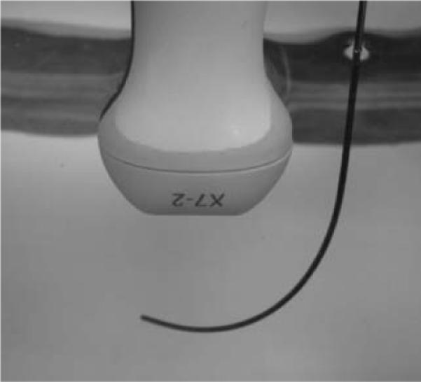
Experiments were performed in a water tank as shown in Fig. 1. Three dimensional ultrasound images were acquired using a Philips IE33 (www.philips.com) with a 3D probe. The probe was mounted as shown in a linear stage while a piecewise constant curvature rod was submerged and mounted on a rotary stage. The sample rods employed in the experiments corresponded to both curved and straight concentric tube robots [8]. These robots are composed of NiTi tubes. For the configuration depicted in Fig. 1, the distal portion had a radius of curvature of R1 = 60 mm and a diameter of 2 mm. Standard settings of the imaging parameters were used during image generation, including 50% overall gain and 50% compression rate, frequency fusion mode 2.
Fig. 1.

Water tank experiment.
A. Results
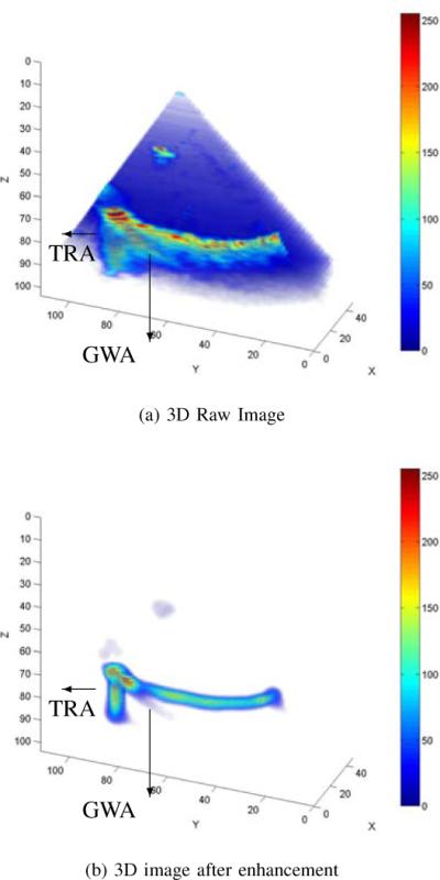
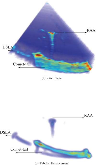
To illustrate the capabilities of the algorithm, two examples are shown in Figs. 2 and 3. Substantial artifacts can be observed in both of the raw images. Most of these artifacts arise due to reverberation effects in which the acoustic energy reflects repeatedly at boundaries of differing acoustic impedance. These boundaries occur at the tube-water interface and the shape of the artifact corresponds to the manner in which some fraction of each reflection returns to the transducer and is inaccurately mapped to a location in image space corresponding to time of return.
Fig. 2.

Tubular instrument image with artifacts: Guide Wave Artifact, GWA and Tip Reverberation Artifact, TRA. (a) raw image. (b) result of tubular enhancement algorithm.
Fig. 3.

Tubular instrument image with artifacts: CT, Comet Tail; DSLA, Diffractive Side Lobe Artifact; and RAA, Range Ambiguity Artifacts. (a) raw image. (b) result of tubular enhancement algorithm.
For example, Guide Wave Artifacts (GWA) are reverberations due to the sound wave traveling along the tubular instrument and eventually emanating from the instrument end or at discontinuities in its cross section. These artifacts can appear as fingers, as shown in Fig. 2 (a). For this type of artifact, the proposed algorithm can suppress the blurred region, but cannot eliminate it if the artifact itself resembles a tubular object with the same length scale (diameter) as the tubular instrument, as shown in Fig. 2 (b). Tip Reverberation Artifact (TRA) is produced from a particularly strong reverberation at the tool-tip, as shown in Fig. 2.
As a second example, Comet Tail Artifacts (CTA) appear as band-like structures on the opposite side from the transducer and are strongest when the tube surface is orthogonal to the scan lines. As shown in Fig. 3, these artifacts can occur along the entire length of the tube when the tube curvature is similar to beam curvature and the tube is placed conformal to the beam sector. As can be seen in both figures, the proposed tubular enhancement algorithm is very effective at reducing comet tail artifacts since the artifact is arranged in a plate-like pattern that can be well distinguished from a tubular structure. These artifacts resemble a shadow of the instrument after the tubular enhancement, as shown in Fig. 3 (b).
Other artifact types that possess tubular structure that can be seen in these figures are Range Ambiguity Artifacts (RAA) and Diffractive Side Lobe Artifacts (DSLA). DSLA arise from the corner or tip of the tubular instruments and are caused by the change of directions and intensities of the sound waves after passing through an aperture or sharp tip. This artifact can be partially reduced by tubular enhancement algorithm as shown in Fig. 3. RAA are generated when multiple internal reflections cause sound returning from a prior pulse to be interpreted as a return from the most recent pulse. This artifact may occur with reverberation artifacts and as shown Fig. 3, it results in an artifact appearing between the transducer and the tubular instrument.
Since each of these artifacts has a tubular structure, they are not completely suppressed by the proposed algorithm. The algorithm does, however, render them easily distinguishable from the instrument and so makes it possible to remove them by additional post-processing using, for example, motion history.
B. Diameter Estimation Accuracy
In general, it is hard to identify the diameter of the tubular structure in a 3D ultrasound volume before any processing of artifact reductions, as illustrated in Fig. 3 (a). However, we are able to do so after the proposed tubular enhancement processing, as the boundary is clearly illustrated, such as in Fig. 3 (b).
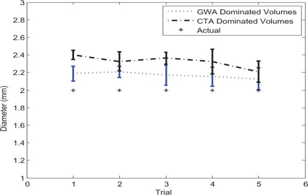
As the diameter of the tubular instrument is known, we can quantify the performance of improvement by comparing the estimated diameter after tubular enhancement with the true diameter. The diameter is manually estimated by taking the average of diameter measurements near the distinct ends and the middle of the enhanced tubular structure, excluding the obvious distorted portions. We ran five tests for the ultrasound volumes with dominating artifacts of GWA, such as in Fig. 2, and another five tests with dominating Comet Tail Artifacts (CTA), such as in Fig. 3. CTA dominate when the tangent of the curved tube is roughly normal to the scan lines. GWA dominate when the tangent of the curved tube tip is less than 45 degrees from parallel to the scan lines. We can see from Fig. 4 that the estimated diameter is always larger than the actual, since artifacts blur the image. Artifacts which affect the entire length of the instrument increase the diameter more than those artifacts which are only present over a small fraction of the total length. Therefore, CTA dominated images produce a larger diameter than GWA dominated images.
Fig. 4.

Tube diameter estimation from 3D ultrasound volumes dominated by two different artifacts: GWA and CTA, with comparison to the known tube diameter.
C. Discussion
The proposed algorithm is a one pass filter for enhancing tubular structures using eigensystem analysis of the Hessian matrix. If the artifacts demonstrate a ghost image of the tubular instruments, the filter cannot distinguish it. In this case, prior information, such as the curvature profile can be incorporated to further remove the unwanted structures. For example, after tubular enhancement, the guide wave artifacts appear as finger-like tubes pointing in very different directions from the actual tubular instrument, and hence they can be distinguished by tube direction analysis.
IV. Conclusions
Motivated by the need for image-guided instrument navigation techniques in minimally invasive interventions, this paper has focused on employing tubular structure enhancement to disambiguate ultrasound imaging artifacts from the interventional instrument. In our experiments, we reproduced many of the previously reported types of 3D artifacts and evaluated algorithm performance. The algorithm was particularly effective in reducing the observed instrument to its actual location and diameter by favoring the tubular surface facing the probe. Those artifacts that also possess a tubular structure of the same scale cannot be eliminated by this approach. They can, however, be distinguished from the instrument based on their location and orientation with respect to the instrument.
Acknowledgments
This work was supported by the National Institutes of Health under grants R01HL073647 and R01HL087797.
References
- [1].Cannon J, Stoll J, Salgo I, Knowles H, Howe R, Dupont P, Marx G, del Nido P. Real-time three-dimensional ultrasound for guiding surgical tasks. Computer aided surgery. 2003;8(no. 2):82–90. doi: 10.3109/10929080309146042. [DOI] [PubMed] [Google Scholar]
- [2].Stoll J, Dupont P. Passive markers for ultrasound tracking of surgical instruments. Medical Image Computing and Computer-Assisted Intervention-MICCAI 2005. 2005:41–48. doi: 10.1007/11566489_6. [DOI] [PubMed] [Google Scholar]
- [3].Novotny P, Stoll J, Vasilyev N, Del Nido P, Dupont P, Zickler T, Howe R. GPU based real-time instrument tracking with three-dimensional ultrasound. Medical image analysis. 2007;11(no. 5):458–464. doi: 10.1016/j.media.2007.06.009. [DOI] [PMC free article] [PubMed] [Google Scholar]
- [4].Yuen S, Kettler D, Novotny P, Plowes R, Howe R. Robotic motion compensation for beating heart intracardiac surgery. The International Journal of Robotics Research. 2009;28(no. 10):1355. doi: 10.1177/0278364909104065. [DOI] [PMC free article] [PubMed] [Google Scholar]
- [5].Boctor EM, Choti MA, Burdette EC, Webster RJ., III Three-dimensional ultrasound-guided robotic needle placement: an experimental evaluation. The International Journal of Medical Robotics and Computer Assisted Surgery. 2008;4(no. 2):180–191. doi: 10.1002/rcs.184. [Online]. Available: http://dx.doi.org/10.1002/rcs.184. [DOI] [PMC free article] [PubMed] [Google Scholar]
- [6].Yan P. MO-FF-A4-02: Automatic Shape-Based 3D Level Set Segmentation for Needle Tracking in 3D TRUS Guided Prostate Brachytherapy. Medical Physics. 2010;37:3366. doi: 10.1016/j.ultrasmedbio.2012.02.011. [DOI] [PubMed] [Google Scholar]
- [7].Ding M, Cardinal HN, Guan W, Fenster A. In: Automatic needle segmentation in 3d ultrasound images. no. 1. Mun SK, editor. vol. 4681. SPIE; 2002. pp. 65–76. [Online]. Available: http://link.aip.org/link/?PSI/4681/65/1. [Google Scholar]
- [8].Dupont P, Lock J, Itkowitz B, Butler E. Design and control of concentric-tube robots. Robotics, IEEE Transactions on. 2010;26(no. 2):209–225. doi: 10.1109/TRO.2009.2035740. [DOI] [PMC free article] [PubMed] [Google Scholar]
- [9].Ren H, Vasilyev NV, Dupont PE. Detection of curved robots using 3d ultrasound. IEEE/RSJ International Conference on Intelligent Robots and Systems, submitted; 2011. [DOI] [PMC free article] [PubMed] [Google Scholar]
- [10].Ortmaier T, Vitrani M-A, Morel G, Pinault S. Robust real-time instrument tracking in ultrasound images for visual servoing,” in Robotics and Automation, 2005. ICRA 2005. Proceedings of the 2005 IEEE International Conference on.2005. pp. 2167–2172. [Google Scholar]
- [11].Huang J, Triedman JK, Vasilyev NV, Suematsu Y, Cleveland RO, Dupont PE. Imaging artifacts of medical instruments in ultrasound-guided interventions. J Ultrasound Med. 2007;26(no. 10):1303–1322. doi: 10.7863/jum.2007.26.10.1303. [Online]. Available: http://www.jultrasoundmed.org/cgi/content/abstract/26/10/1303. [DOI] [PubMed] [Google Scholar]
- [12].Frangi A, Niessen W, Vincken K, Viergever M. Multiscale vessel enhancement filtering. Medical Image Computing and Computer-Assisted InterventationMICCAI98. 1998:130–137. [Google Scholar]


