Abstract
Over the last decade electrical batteries have emerged as a critical bottleneck for portable electronics development. High-power mechanical energy harvesting can potentially provide a valuable alternative to the use of batteries, but, until now, a suitable mechanical-to-electrical energy conversion technology did not exist. Here we describe a novel mechanical-to-electrical energy conversion method based on the reverse electrowetting phenomenon. Electrical energy generation is achieved through the interaction of arrays of moving microscopic liquid droplets with novel nanometer-thick multilayer dielectric films. Advantages of this process include the production of high power densities, up to 103 W m−2; the ability to directly utilize a very broad range of mechanical forces and displacements; and the ability to directly output a broad range of currents and voltages, from several volts to tens of volts. These advantages make this method uniquely suited for high-power energy harvesting from a wide variety of environmental mechanical energy sources.
 High-power mechanical energy harvesting could be an alternative to batteries, but efficient energy conversion technology has been missing. Here, a novel mechanical-to-electrical energy conversion method is described that is based on reverse electrowetting and is uniquely suited for high-power energy harvesting.
Energy harvesting is a very old idea arguably going back to the invention of the windmill, sail and waterwheel. More recently efforts have been focused on ways to convert environmental energy into electrical power. Many types of energy harvesters exist covering a very broad range of applications from large-scale power generators to portable power sources for mobile devices and sensors. The harvesting of environmental mechanical energy is particularly promising for portable applications by using such high-power sources as human locomotion, but currently its use is substantially limited by low power output of energy converters. Existing methods of mechanical-to-electrical energy conversion such as electromagnetic, piezoelectric, or electrostatic are not well suited for effective direct coupling to the majority of high-power environmental mechanical energy sources suitable for portable applications, thus their energy output remains in the microwatt to hundreds of milliwatt range1,2,3. However with the rapid growth of mobile devices the demand for power sources producing watts or tens of watts has acutely increased.
To bridge this gap, we have developed a radically new mechanical-to-electrical energy conversion method that is based on reverse electrowetting—a novel microfluidic phenomenon4. Energy generation is achieved through the interaction of arrays of moving microscopic liquid droplets with a novel multilayer thin film. We believe that this approach has a number of significant advantages, over existing mechanical-energy-harvesting technologies, including very high power densities, up to 103 W m−2, ability to directly utilize a very broad range of mechanical forces and displacements, including those not accessible by traditional piezoelectric or electromagnetic methods, and ability to output a broad range of currents and voltages, from several volts to tens of volts without the need for up or down voltage conversion.
Results
Reverse electrowetting concept
The motion of a conductive liquid on a dielectric-coated conductive substrate has been extensively studied in the past as a part of electrowetting-on-dielectric (EWOD) phenomenon5. In a classical electrowetting experiment liquid spreading on the dielectric surface is facilitated by electrically induced increase in the dielectric surface wettability5. The wettability change arises from the extra electrostatic energy that is associated with the electrically charged liquid–solid interface, which is formed when the voltage from an external source is applied between the conductive droplet and the dielectric-film-coated electrode.
It can be shown5 that this extra electrostatic energy and the liquid–solid interfacial energy σsl can be combined to produce Lippmann's effective solid–liquid interfacial energy σsleff=σsl−CV2/2, where V is the voltage applied between the conductive droplet and the dielectric-film-coated electrode and C is the capacitance per unit area of the liquid–solid interface. On inserting Lippmann's effective interfacial tension into classical Young's equation5 for the droplet contact angle θ, one obtains the electrowetting equation5 cos θ=cos θ0+CV2/2σlv, where σlv is the liquid-vapor interfacial energy and θ0 is the initial droplet contact angle where no voltage is applied. The electrowetting equation predicts that the droplet contact angle θ should decrease with the increase in the applied voltage. As a result the droplet tends to spread and position itself in such a way as to maximize its overlap with the dielectric-film-coated electrode. Thus, in a classical electrowetting experiment, the electrical energy is converted into mechanical energy of liquid motion through electrically induced change in the dielectric surface wettability.
Here we employ a new approach that allows one to run this process in reverse, converting mechanical energy of liquid motion into electrical current, thus achieving reverse electrowetting (REWOD). Because REWOD is a novel phenomenon, which had not been previously described in the literature, a detailed description of the physics of the REWOD process is lacking. In this work, we report only our initial results that provide the fundamentals of the process.
In its essence, the REWOD process is conceptually straight forward. The droplet and the electrode are connected to the external electrical circuit that provides a constant bias voltage between the droplet and the electrode. External mechanical actuation is used to move the droplet in such a way as to force a decrease of its overlap with the dielectric-film-coated electrode. This results in the decrease of the total charge that can be maintained at the droplet liquid–solid interface. The excessive electrical charge then flows back through the electrical circuit that connects the droplet and the electrode, generating electrical current that can be used to power the external load.
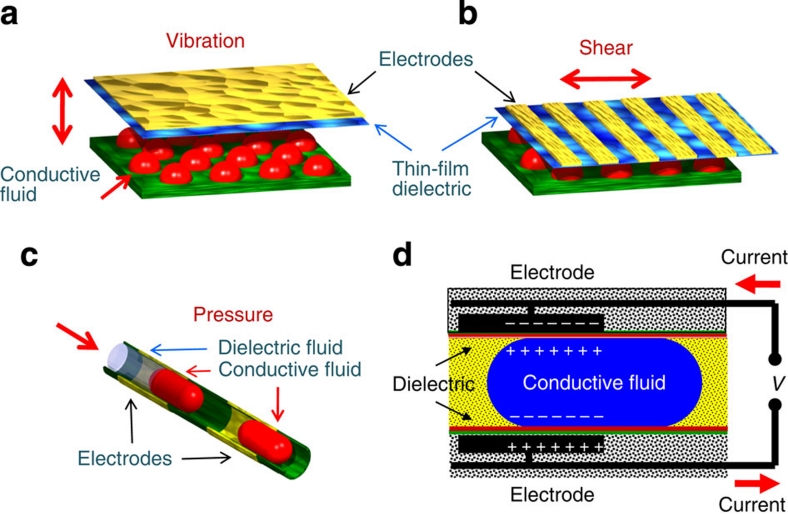
In the REWOD process, fluidic actuation can be accomplished in a number of different geometries, as shown in Figure 1, such as out-of-plane vibration, in-plane shear, and in-channel droplet motion. To further illustrate the main principle of the REWOD operation, let us consider the case of a droplet confined in a channel as shown in Figure 1c. As the droplet moves in and out of alignment with the electrified thin-film-dielectric-coated electrodes, the amount of the electrical charge at the electrodes changes causing electrical current to flow as shown in Figure 1d.
Figure 1. Schematics of three major droplet actuation mechanisms.
These include (a) droplets between oscillating plates, (b) droplets between sliding plates, and (c) droplets in a microchannel. (d) Shows in greater detail schematics of reverse-electrowetting-based energy generation process in a microchannel geometry.
In the simplest approximation, we can neglect the intricacy of the wetting–dewetting process associated with the motion of liquid droplets during the REWOD process and treat each droplet simply as a variable capacitor. In this approximation, the REWOD process behaves similarly to the classical variable-capacitance-based energy generation. Thus, the electrical energy produced per unit area of the composite liquid/thin-film-dielectric/solid interface during the REWOD process is directly proportional to the interfacial electrical capacitance and to the square of the voltage applied across the interface.
Even though the above description helps to elucidate the fundamentals of the REWOD process, it fails to account for several important phenomena associated with the wetting–dewetting process that substantially influence the actual energy-generation process. In particular, it does not account for such phenomena as contact line hysteresis and surface charge trapping that impose important limitations on the energy density per unit area that can be generated using the REWOD approach.
Contact angle hysteresis is well known to adversely affect classical electrowetting (EWOD)5. In its most severe form, contact angle hysteresis leads to 'pining' of the position of the contact line, preventing droplet spreading in response to the applied voltage during the EWOD process. Similarly, in the REWOD process contact line pinning hinders fluid actuation, thus impeding energy generation. The influence of the contact line hysteresis on the REWOD and EWOD process can be substantially mitigated by a proper choice of the polymeric coating that contacts the conductive liquid5. In particular, fluoropolymers, such as Cytop6 used in this work, are known to provide low-hysteresis surface with the contact angle hysteresis less than 5°.
Surface charge trapping is another phenomenon that can substantially reduce energy production during the REWOD process. In dielectric films with thicknesses of only a few tens of nanometers, even a few volts can result in very strong electric fields on the scale of 106 V cm−1. As a result, electrical carrier injection and subsequent charge trapping in the dielectric film often take place7,8. This essentially causes immobilization of some portion of the electrical charge in the dielectric, impeding charge collection during the dewetting process and, thus, reducing energy generation efficiency.
An extensive investigation was performed to determine the optimum materials needed to maximize energy production and to limit charge trapping for the REWOD process, of which an extended discussion can be found in the Methods section. Ultimately, liquid metals, Hg and Galinstan9, gave the best results for the conducting liquid. The optimized thin dielectric stack consisted of Ta2O5 coated with a thin film of fluoropolymer (Cytop6). The Ta2O5 film possessed superior resistance to voltage breakdown, whereas the Cytop film was necessary to reduce charge trapping and prevent contact angle hysteresis.
REWOD energy production
Successful high-power mechanical energy harvesting using the proposed approach is contingent on solving three major problems, namely achieving high level of electrical energy generation per unit area of the liquid–solid interface; attaining efficient mechanical actuation and electrical energy generation by the individual droplets; and demonstrating synchronous generation of electrical energy by a group of micro-droplets working in parallel.
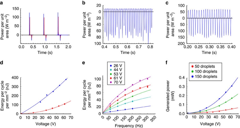
Typical results for the instantaneous power per unit area of the liquid–solid interface generated during the REWOD process using each of the three actuation methods described above are shown in Figure 2a–c. The overall form of the curves and the level of generated power (~102 W m−2) are quite similar in all three cases. The results shown in Figure 2a clearly support the premise that Galinstan and Hg behave very similarly during the REWOD process.
Figure 2. Power and energy generated at the resistive load R.
The electrical circuit used is shown in Figure 8. (a) Instantaneous power generated by a droplet of Galinstan (blue) and a droplet of Mercury (red) between oscillating plates. A single droplet was measured with the liquid-substrate overlap area of about 1 mm2 (Fig. 7). (b) Instantaneous power generated by a train of 22 Hg droplets in a channel. Each droplet had about 5.8 mm2 liquid-substrate overlap area (Fig. 5). (c) Instantaneous power generated by an array of 50 Hg droplets between sliding plates. Each droplet had about 0.28 mm2 liquid-substrate overlap area (Fig. 6). (d) Energy generated per unit area per one oscillation cycle as a function of bias voltage. Results for a single Hg droplet with about 1 mm2 liquid-substrate overlap area between oscillating plates (16 nF cm−2 capacitance) are shown in blue, and results for 22 Hg droplets in a channel (5 nF cm−2 capacitance, about 5.8 mm2 liquid-substrate overlap area per droplet) are shown in red. Dots represent the actual experimental data; solid lines represent the best parabolic fit. (e) Energy generated per unit area per one oscillation cycle for the case of sliding plates actuation (3.4 nF cm−2 capacitance, 50 Hg droplets, about 0.28 mm2 liquid-substrate overlap area per droplet) as a function of the oscillation frequency. Dots represent the actual experimental data; solid lines represent the best fit using equation (1). (f) Average power generated by an array of Hg droplets between sliding plates as a function of bias voltage for 100 Hz oscillation frequency. Circular periodic arrays of 50, 100 and 150 droplets were formed by placing the droplets in one, two or three concentric rings as explained in the Methods section. The results for the arrays of 50, 100 and 150 droplets with the combined liquid-substrate overlap areas of 14.1, 28.2, and 42.3 mm2, respectively, are shown. Dots represent the actual experimental data; solid lines represent the best parabolic fit.
Integration of the instantaneous power curves over one oscillation period allows calculation of the energy generated per unit area per one oscillation cycle, which is one of the most important characteristics of the REWOD process. From the results shown in Figure 2d, one can see that energy of almost 0.4 μJ mm−2 is obtained for the dielectric film stack with 16 nF cm−2 capacitance.
The dependence of the charge displaced per unit area per cycle on the bias voltage was linear for thicker films with 5 nF cm−2 capacitance, but showed substantial deviation from the linear behaviour at high voltages for thin films with capacitance about 16 nF cm−2. For thin films, this caused substantial deviation of the generated energy per unit area per cycle from the ideal quadratic dependence on the bias voltage. Indeed, as shown in Figure 2d, for the thicker films with 5 nF cm−2 capacitance, the curve for generated energy per unit area per cycle exhibits an obvious parabolic shape. However, for the thin films with 16 nF cm−2 capacitance, the energy curve has an almost a linear shape, indicating that the charge displaced per unit area per cycle is growing more slowly than a linear function of the bias voltage. This reinforces the notion that a simple ideal capacitor model does not fully describe the REWOD process at high electric fields.
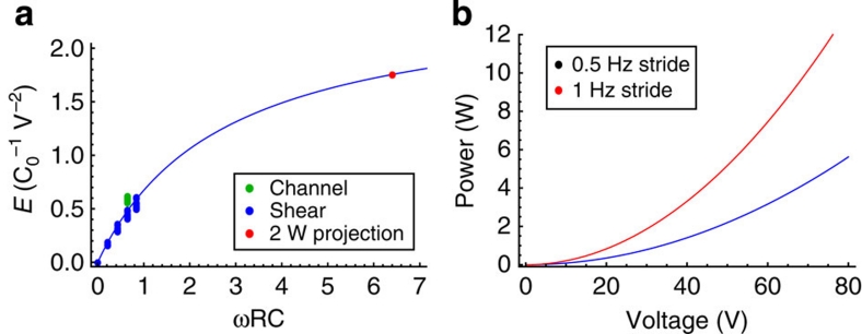
The dependence of the REWOD energy generation on the wetting–dewetting frequency and the number of droplets was investigated using sliding-plates actuation as shown in Figure 1b. In Figure 2e, the dependence of the average energy density per one wetting–dewetting cycle is plotted as a function of wetting–dewetting frequency for five different voltages. The energy produced per cycle increased with the frequency for all five voltages. As discussed below, these experimental data can be collaped onto a single master curve by an appropriate scaling as shown in Figure 3a. This type of behaviour is expected from the theoretical description of the REWOD process, as will become evident from the subsequent discussion.
Figure 3. Plots of energy generated and predicted power.
(a) Shows energy generated per one oscillation cycle (in units of C0V2 ) as a function of dimensionless parameter ωRC0. The solid line represents equation (1). Experimental data for the droplets between sliding plates are shown in blue, and experimental data for the droplets in a channel are shown in green. The red dot represents the predicted energy for a train of 1,000 droplets. (b) Shows the predicted power for a train of 1,000 droplets as a function of the bias voltage. Calculations are for of a load impedance of 2 KΩ and a film-stack capacitance of 16 nF cm−2. The red curve corresponds to 1-Hertz stride (fast walk) and the blue curve to 0.5-Hertz stride (leisure walk).
To investigate the dependence of the average generated power on the number of droplets, the performance of the sliding plates set-up was studied for the cases of 50, 100 and 150 droplets. The droplets were arranged in concentric circular arrays (50 droplets in each ring) as explained in the Methods section. The results are shown in Figure 2f. As expected the overall power produced by a set of droplets increased with the number of droplets working in parallel.
However, the generated power is growing faster than linear with the number of droplets, because the average power generated by each of the droplet rings is different. Indeed, the power depends on the ring diameter because the effective wetting–dewetting period is decreasing with the increase in the linear sliding velocity for the electrode pattern with the fixed electrode strip width. The droplets in the outer ring are experiencing a lower wetting–dewetting period (or, equally, higher effective frequency) and thus generate more power per droplet than the droplets in the inner ring.
REWOD model
The average energy E generated per one wetting–dewetting cycle and the average generated power P can be theoretically analysed using a simple analytical model (see Supplementary Methods for details). The following results were obtained:
| 1 |
| 2 |
where R is the load impedance, C0=ɛ0kAh−1 is the maximum capacitance of the variable capacitor (that is, REWOD unit), V is the bias voltage, A is the maximum overlap area between the droplets and the electrodes achieved during the wetting–dewetting cycle, h is the thin film dielectric thickness, k is the thin film dielectric constant, ɛ0 the vacuum permittivity, and ω=2πT−1 is the capacitance oscillation frequency, where T is characteristic period of one wetting–dewetting cycle.
The theoretical curve described by equation (1) is plotted in Figure 3a as a solid line. The shape of this curve is similar to the experimental curves shown in Figure 2e. To quantitatively compare theoretical predictions with the experimental data, the results for the average energy density per one wetting–dewetting cycle presented in Figure 2d,e are re-plotted in Figure 3. As one can see, both the channel set-up data and the sliding plates set-up data collapse onto the same theoretical curve, supporting the validity of the model.
Discussion
The results described above establish the fundamentals of energy production using REWOD process and clearly demonstrate that the energy-generation process can be readily scaled upwards to achieve high power output in excess of 1 W in a relatively small package. Indeed, scaling up the REWOD-based energy-generation process entails increasing the number of droplets working in parallel to generate electrical current. In this work, we have experimentally demonstrated that this scaling can be readily achieved over two orders of magnitude, from a single droplet to 150 droplets. In terms of the liquid-substrate area, the scaling was demonstrated over almost three orders of magnitude, from 0.28 mm2 (single droplet in the sliding plates set-up) to 1.28 cm2 (22 droplets in a channel set-up, each droplet having 5.8 mm2 liquid-substrate overlap area). As the total capacitance of the system C linearly scales with the area, it was demonstrated to scale over three orders of magnitude as well, from 14 pF (single droplet in the sliding plates set-up, 5 nF cm−2 dielectric stack) to 20 nF (22 droplets in a channel set-up, 16 nF cm−2 dielectric stack).
Devices with even larger number of droplets can be readily fabricated by exploiting a natural synergy between the REWOD process and droplet-based microfuidics10. Indeed, parallel actuation of a large number of micro-droplets required for scaling-up of the generated power is routinely performed in channel-based droplet macrofluidic devices, where thousands of droplets can be synchronously moved in microchannels with a great degree of control over their position and velocity10. Combination of REWOD and droplet microfluids offers important advantages such as easy scaling, very flexible force–displacement relationship, and extremely simple device design with no moving solid parts.
Microfluidic power generators based on the REWOD process can take advantage of many previously inaccessible environmental mechanical energy sources. Two specific examples will be illustrated: energy harvesting from human locomotion and high-power harvesting of mechanical vibration energy.
Energy harvesting from human locomotion using footwear-embedded harvesters is a long-recognized concept1,11,12,13. Data available in the literature indicate that up to 10 W per foot can be generated without adversely affecting a person's gait13. For comparison, relatively high-power mobile electronic devices, such as cell phones and mobile computers, typically consume power on the order of 1 and 15 W respectively.
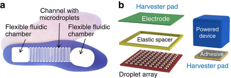
The following simple estimate illustrates the power that can be produced by a footwear-embedded microfluidic harvester using the REWOD process. Let us consider 2-m-long train of 1,000 conductive droplets, each 1 mm long separated by 1 mm spacers and positioned inside 1-mm-diameter circular cross-section channel with the total length of 4 m, Figure 4a. The total area covered by such channel is about 40 cm2 or less than ¼ of the area of a typical human footprint. The total volume of the liquid contained in the channel would be about 4 ml, which makes it readily compatible with footwear. Assuming that the heel area is about 20 cm2, we estimate that the total midsole compression required to achieve 4 ml volume displacement is around 2 mm. Such a displacement is well below the level that might affect the person's gait.
Figure 4. Schematics of two REWOD applications.
(a) Footwear-embedded microfluidic energy harvester and (b) a REWOD-based vibration harvester.
Let us consider the case of the film stack with the capacitance of 16 nF cm−2. The average generated power calculated using equation (2) is shown in Figure 3b. The average power per foot can exceed 2 W for bias voltages in excess of 35 V and 10 W for bias voltages in excess of 75 V. The bias voltage can be substantially reduced by increasing the capacitance of the dielectric film stack. However, it is important to mention, that even at its current level the bias voltage does not present a substantial practical issue. A wide range of commercially available DC–DC boost converter components can be used to convert the 3.7 V output of standard Li-ion batteries to the required bias voltage. Thus, this example clearly supports the use of footwear designed for high-power-energy harvesting based on reverse electrowetting.
The other common source for mechanical energy harvesting is vibration energy. It has been demonstrated that the energy of mechanical vibrations present in floors, stairs, vehicles and equipment housings can be used for electrical power generation1,3,14. Currently, the majority of experimental vibration harvesters have output power in the range from 10−6 to 10−2 W (refs 1,3,14). The REWOD process can enable the use of novel harvester architectures with greatly increased power output. One example of the REWOD-based vibration harvester device consists of an array of conductive droplets squeezed between two dielectric-coated electrodes, as shown in Figure 4b. The electrodes are separated by a millimeter-thick elastic spacer so that the resulting structure can be used as a mounting 'pad' for the load device. Mechanical vibration of the load device causes periodic change in the solid–liquid contact area and, thus, electrical current generation. For the film stack with a capacitance of 102 nF cm−2, the resulting power density can be scaled up to 10−1 W cm−2 at 50 Hz vibration frequency, thus enabling the fabrication of practical vibration harvesters with power output of several watts.
The above examples illustrate new possibilities in portable high-power energy harvesting that can be opened by utilizing the REWOD process. High-power energy harvesting can potentially provide a valuable alternative to the use of batteries. Even though energy harvesting is unlikely to completely replace batteries in the majority of mobile applications, it can have a very important role in reducing cost, pollution, and other problems associated with battery use. We believe that the REWOD-based mechanical to electrical energy conversion process, which we have developed, can go a long way in achieving this goal.
Methods
REWOD droplet actuation methods
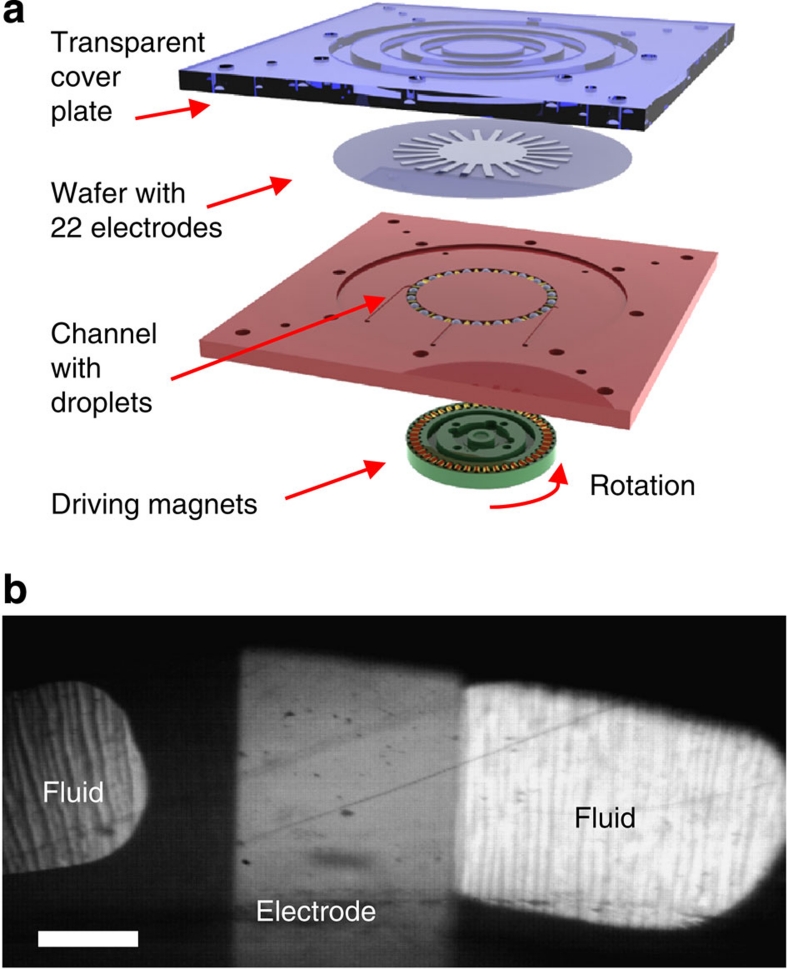
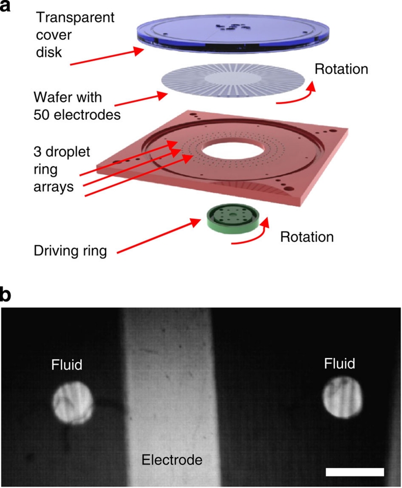
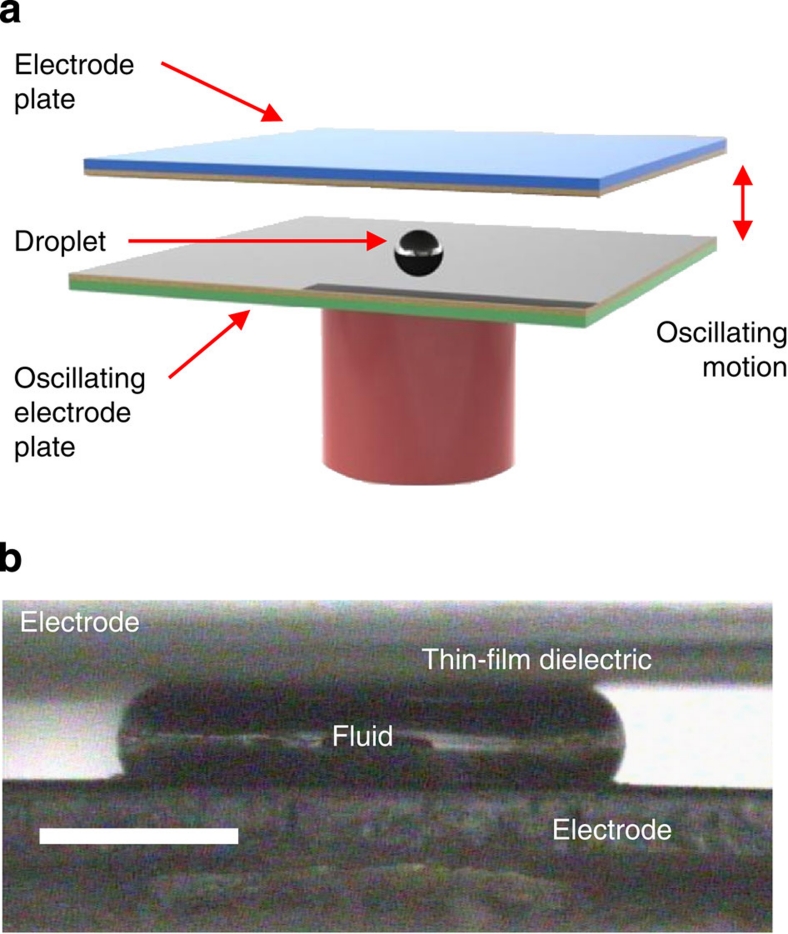
In this work, we have investigated all three major droplet actuation methods described above, that is, droplets between oscillating plates, droplets between sliding plates, and droplets in a microchannel, (Fig. 1). In the case of a microchannel, a train of 22 droplets separated by rigid spacers (magnetic balls or cylinders) was formed in a circular trench as shown in Figure 5. The unfilled channel space between droplets was either filled by air or by an inert dielectric liquid. A quartz wafer with the patterned electrodes covered by the thin-film dielectric stack was placed on top of the trench, forming a channel. The droplets were actuated by rotating a set of magnets positioned underneath the channel and magnetically coupled to the droplet spacers. Rotation was performed by a computer-controlled stepping motor. The sliding plates actuation was achieved by forming circular periodic ring arrays of liquid droplets protruding from a set of small holes in a planar substrate (three rings with the radii of 27, 32 and 37 mm, total of 50 droplets in each ring) and placing a quartz wafer with the patterned electrodes covered by the thin-film dielectric stack on top of the droplets, as shown in Figure 6. Sliding motion was achieved by rotating the wafer with respect to the droplets. The wafer was rotated by a computer-controlled stepping motor, using the same control system as in the channel set-up. Finally, in the case of droplets between oscillating plates, a liquid droplet was periodically squeezed between two planar substrates with the electrodes deposited on the surface. Either one or two of these electrodes was covered by a thin-film dielectric stack. The substrates were moved by a computer-controlled linear electromagnetic actuator as shown in Figure 7. The amplitude of oscillation was adjusted to achieve full droplet disconnect from the electrodes at each cycle.
Figure 5. Experimental set-up for droplets in a microchannel.
(a) Schematics of the device and (b) a frame from a high-speed video showing a top view of the droplets overlapping one of the electrodes. Scale bar represents 1 mm.
Figure 6. Experimental set-up for droplets between sliding plates.
(a) Schematics of the device and (b) a frame from a high-speed video showing a top view of the droplets overlapping one of the electrodes. Scale bar represents 1 mm.
Figure 7. Experimental set-up for a single droplet between oscillating plates.
(a) Schematics of the device and (b) a frame from a high-speed video showing a side view of a droplet squeezed between two electrodes. Scale bar represents 0.5 mm.
The electric circuit used to investigate energy generation was identical for all three set-ups. The circuit is shown in Figure 8 and includes a source of a constant bias voltage V, a resistive load R and a variable capacitor C, (the REWOD unit, which represents a harvester set-up, that is, a set of droplets in contact with the electrode grid). The voltage drop across the resistive load was captured by the data acquisition board and converted into electrical current allowing direct calculation of the generated power as a function of time.
Figure 8. Schematics of the electric circuit.
The circuit used to investigate energy generation includes a source of a bias voltage V, a resistive load R, and a variable capacitor C (the REWOD unit, which represents a harvester set-up, that is, a set of droplets in contact with the electrode grid). The voltage drop on the resistive load was captured by the data acquisition board and converted into electrical current allowing direct calculation of the generated power as a function of time. Resistive loads with the values of R in the range from 104 to 106 Ω were investigated. A battery (with internal resistance of about 1 Ω) was used to provide a bias voltage.
Optimization of REWOD materials
For the REWOD process, the electrical energy produced per unit area of the composite liquid/thin-film-dielectric/solid interface is directly proportional to the interfacial electrical capacitance and to the square of the voltage applied across the interface. Thus, to maximize the energy density of such a composite interface, one has to simultaneously maximize the interface capacitance and increase the interface voltage up to the point, just before breakdown occurs. The interface capacitance can be increased by employing high-k dielectric material and by decreasing the thickness of the dielectric film. However, both of those choices can adversely affect the breakdown voltage. Because the energy density depends on the first power of the capacitance and on the second power of the breakdown voltage, the desirable tradeoff to maximize energy density is often difficult to achieve. The problem is further compounded by the fact that the behaviour of the breakdown voltage in the liquid/thin-film-dielectric/solid interfaces is not well understood. In dielectric films with a thickness of only few tens of nanometers, the value of the breakdown voltage exhibits highly nonlinear and complicated dependence on the properties of the materials, as well as on the frequency and polarity of the applied voltage7,8,15,16.
In addition to energy density issues, a number of subtle problems exist, because the energy generation process involves motion of liquid droplets with respect to the electrified substrate. This process causes periodic wetting and dewetting of the substrate surface having the voltage applied across the liquid/thin-film-dielectric/solid interface. As discussed above, for nanometer-thin films, even a few volts can result in very strong electric fields on the scale of 106 V cm−1. This results in electrical carrier injection and subsequent charge trapping in the dielectric film7,8.
One of our first problems was to determine the best conducting and dielectric liquids for the REWOD application. A wide range of dielectric liquids (which were used in the microchannel actuation set-up) from alkanes (decane, dodecane and hexadecane) to silicone oils (polydimethylsiloxane such as DMS-T05, DMS-T11 by Gelest) was found to perform well. A number of conducting liquids such as aqueous salt solutions, molten ionic salts, and liquid metals have shown the REWOD phenomenon. In the course of our investigation, we found that using ions as charge carriers was quite inefficient for energy production, because of strong charge trapping at the interface. Liquid metals proved to be the best exhibiting high electrical conductivity, higher surface tension, and low vapor pressure. Using electrons for charge carriers showed significant improvement in energy production. Higher surface tension is desirable, because the energy per unit area increases as surface tension increases. There are only two choices for liquid metals that remain liquid at room temperature: Hg and Ga/In/Sn alloy or Galinstan9. For reverse-electrowetting, their appropriate properties are similar, but for most of this investigation, Hg was used, because the surface of Galinstan oxidizes rapidly in air9.
However, mercury is undesirable for use in consumer products because of its toxicity. Data presented in Figure 2a show that the same amount of energy can be produced when Galinstan is used as the liquid metal instead of Hg. Galinstan is nontoxic, environmentally benign, and widely used in commercially available consumer products, such as thermometers. The physical properties of Galinstan are equal to or better than mercury for this application. Galinstan has a lower density, lower resistivity and higher surface tension than mercury. As was mentioned above, the major issue with using Galinstan is its fairly rapid oxidation when exposed to air. For the REWOD application, the train of droplets would be fabricated in sealed channels protected from air exposure and contamination from the environment. Many commercially available products are manufactured in an air-free environment, such as Li-ion batteries, thus once the equipment to handle Galinstan is in place, its use should be relatively straight forward.
The next important consideration was to develop a dielectric film optimized for energy production. The electrode capacitance can be increased by using a higher-k material and by decreasing the dielectric layer thickness. Simple calculations indicate that if high capacitance on the order of 102 nF cm−2 is to be achieved at lower working voltages (<100 V), dielectric film thicknesses are limited to several 100 nm, but, as previously noted, field strengths are quite high causing the film to be susceptible to breakdown. We ultimately determined that Ta2O5, possessing a relatively high k of 25, demonstrated the best resistance to dielectric breakdown. The Ta2O5 films were produced by anodic oxidation at room temperature of sputtered deposited Ta films on quartz substrates. Precise Ta2O5 thickness could be controlled by adjusting the anodizing voltage.
Although not completely understood theoretically, we found that charge trapping at the interface between the liquid and the dielectric surface had a dominant role in limiting energy production. The amount of charge trapped at the interface drastically reduces the amount of energy available for use. We investigated numerous dielectrics not only for their breakdown characteristics but also for their tendency to trap charge. As a result, we discovered that all oxide thin films, which we investigated, were poor at energy production. Inorganic fluorides were better, but fluoropolymers or Teflon-like films were by far the best. The fluoropolymer films were produced by spin coating with Cytop6 and then by curing in N2 at 250 °C for 2 h. Although the Cytop films showed the least amount of charge trapping, they demonstrated unreliable breakdown characteristics. Thus, our best results for energy production were obtained using a dielectric composite of Cytop deposited on Ta2O5.
Author contributions
T.K. performed theoretical and experimental work, whereas J.A.T. performed experimental and nanofabrication work.
Additional information
How to cite this article: Krupenkin, T. & Taylor, J.A. Reverse electrowetting as a new approach to high-power energy harvesting. Nat. Commun. 2:448 doi: 10.1038/ncomms1454 (2011).
Supplementary Material
Supplementary Figure S1 and Supplementary Methods.
Acknowledgments
Financial support through NSF SBIR Grant 1013372 is appreciated.
References
- O'Donnell R. Energy harvesting from human and machine motion for wireless electronic devices. Proc. Ieee 96, 1455–1456 (2008). [Google Scholar]
- Poulin G., Sarraute E. & Costa F. Generation of electrical energy for portable devices Comparative study of an electromagnetic and a piezoelectric system. Sensor. Actuat. a-Phys. 116, 461–471 (2004). [Google Scholar]
- Khaligh A., Zeng P. & Zheng C. Kinetic energy harvesting using piezoelectric and electromagnetic technologies-state of the art. Ieee Trans. Ind. Electron. 57, 850–860 (2010). [Google Scholar]
- Krupenkin T. Method and apparatus for energy harvesting using microfluidics. USA patent # 7898096 (2011).
- Mugele F., Duits M. & van den Ende D. Electrowetting: a versatile tool for drop manipulation, generation, and characterization. Adv. Colloid Interface Sci. 161, 115–123 (2010). [DOI] [PubMed] [Google Scholar]
- Lin Y. Y. et al. Low voltage electrowetting-on-dielectric platform using multi-layer insulators. Sensor. Actuat. B-Chem. 150, 465–470 (2010). [DOI] [PMC free article] [PubMed] [Google Scholar]
- Wan Z. L., Zeng H. & Feinerman A. Reversible electrowetting of liquid-metal droplet. J. Fluid. Eng.-T. Asme 129, 388–394 (2007). [Google Scholar]
- Sen P. & Kim C. J. A fast liquid-metal droplet microswitch using EWOD-driven contact-line sliding. J. Microelectromech. 18, 174–185 (2009). [Google Scholar]
- Mohseni K. & Baird E. S. Digitized heat transfer using electrowetting on dielectric. Nanosc. Microsc. Therm. 11, 99–108 (2007). [Google Scholar]
- Teh S. Y., Lin R., Hung L. H. & Lee A. P. Droplet microfluidics. Lab Chip 8, 198–220 (2008). [DOI] [PubMed] [Google Scholar]
- Paradiso J. A. & Starner T. Energy scavenging for mobile and wireless electronics. Ieee Pervas. Comput. 4, 18–27 (2005). [Google Scholar]
- Shenck N. S. & Paradiso J. A. Energy scavenging with shoe-mounted piezoelectrics. Ieee Micro 21, 30–42 (2001). [Google Scholar]
- Starner T. Human-powered wearable computing. IBM Syst. J. 35, 618–629 (1996). [Google Scholar]
- Beeby S. P., Tudor M. J. & White N. M. Energy harvesting vibration sources for microsystems applications. Meas. Sci. Technol. 17, R175–R195 (2006). [Google Scholar]
- Berry S., Kedzierski J. & Abedian B. Low voltage electrowetting using thin fluoroploymer films. J. Colloid Interface Sci. 303, 517–524 (2006). [DOI] [PubMed] [Google Scholar]
- Novkovski N., Skeparovski A. & Atanassova E. Charge trapping effect at the contact between a high-work-function metal and Ta2O5 high-k dielectric. J. Phys. D 41, 105302 (2008). [Google Scholar]
Associated Data
This section collects any data citations, data availability statements, or supplementary materials included in this article.
Supplementary Materials
Supplementary Figure S1 and Supplementary Methods.


