Abstract
We developed and validated silicon-based neural probes for neural stimulating and recording in long-term implantation in the brain. The probes combine the deep reactive ion etching process and mechanical shaping of their tip region, yielding a mechanically sturdy shank with a sharpened tip to reduce insertion force into the brain and spinal cord, particularly, with multiple shanks in the same array. The arrays’ insertion forces have been quantified in vitro. Five consecutive chronically-implanted devices were fully functional from 3 to 18 months. The microelectrode sites were electroplated with iridium oxide, and the charge injection capacity measurements were performed both in vitro and after implantation in the adult feline brain. The functionality of the chronic array was validated by stimulating in the cochlear nucleus and recording the evoked neuronal activity in the central nucleus of the inferior colliculus. The arrays’ recording quality has also been quantified in vivo with neuronal spike activity recorded up to 566 days after implantation. Histopathology evaluation of neurons and astrocytes using immunohistochemical stains indicated minimal alterations of tissue architecture after chronic implantation.
Keywords: Auditory prostheses, biomicroelectromechanical systems, electrical stimulation, implantable electrodes, iridium oxide
I. INTRODUCTION
IMPLANTABLE microelectrode systems based on batch processing and micromachining techniques continue to evolve and expand their applications in treating diseases and disorders in the central and peripheral nervous systems, as well as advancing basic neuroscience. Applications include rehabilitation following spinal cord injury and sensory deficits such as hearing loss. Recovery of limb movements by paralyzed persons may be assisted by brain–machine interfaces using recording micro-electrodes. In the future, devices for the treatment of neurodegenerative diseases, including Parkinson's disease, epilepsy, and depression, may employ microelectrodes. Batch-processed microelectrodes have been developed using a variety of substrates, including silicon [1], [2], silicon-on-insulator [3], ceramic [4], and metal [5]. Despite these advances, there has been limited progress in demonstrating chronically-implantable systems that can continue to function for many months.
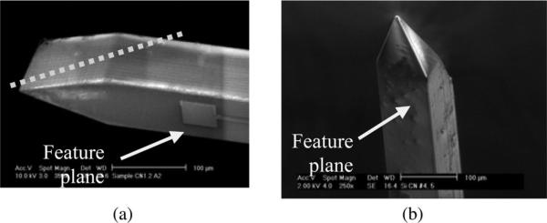
We previously introduced a novel way of fabricating silicon-based microelectrode arrays [6]–[8], and in this report, the details of the fabrication processes, the chronic implantation, electrochemical characterization, and tissue studies are presented. The use of deep reactive ion etching (DRIE) has enabled the formation of probe shanks with a range of thicknesses, which is an alternative to the dopant concentration-based wet etching process [9]. The DRIE process increases stiffness, for example, by a factor of eight for each doubling of the probe's thickness [10]. A drawback of the DRIE technique, however, is that it yields wedge-shaped tips [see Fig. 1(a)], and it has been difficult to shape the out-of-plane dimensions [5], [11]. We combined the DRIE technique and mechanical grinding of the probe tips, resulting in a configuration that is pointed in two planes, as shown in Fig. 1(b). This method enables a true 3-D tip configuration with excellent reproducibility. Table I shows a comparison of different methods of shaping the probe tips. Although the effect of probe tip shape on tissue response remains debatable [12]–[13], a reduced tip profile does lessen the insertion force into the tissue [10], [14] and reduces probe bending or buckling. In addition, arrays with multiple shanks require higher insertion force, and therefore, a pointed tip profile facilitates scaling of the number of shanks without excessive dimpling during the penetration of the pia mater.
Fig. 1.
Shapes of the tips in silicon-based probes. (a) Scanning electron microscopic (SEM) of a 100-μm-thick tip of a probe after DRIE. The dotted line shows the approximate portion of the tip region to be ground out. (b) True 3-D tip, formed by mechanical grinding.
TABLE I.
Methods to Shape Probe Tips
| Grinding | Doped Etch-stop | Wet-Etching | |
|---|---|---|---|
| References | This article | [16, 17] | [18-20] |
| Fabrication | Easy | Difficult | Moderate |
| Wafer Orientation Requirement | No | No | Yes |
| Etching Mask needed | No | Yes | Yes |
| Etching Angles | Flexible; Independently controlled | Limited | Limited |
| Advantages | Economical. Any angle. | Batch process | Batch process |
| Disadvantages | Serial process | Requires dopant dosing | Fixed angle only; rough surface |
Maintaining the electrical integrity of chronically-implanted microelectrodes is an important and challenging task. The use of low-pressure chemical-vapor deposition (LPCVD) silicon oxide and nitride films as insulating materials precluded the use of commonly-used metals such as gold and titanium as interconnect traces because of LPCVD's high temperature requirement [9]. As a result, the process required using a conductive material such as polysilicon, which in turn, requires doping to lower its resistivity, adding to the complexity of the wafer processing. We used the low-temperature plasma-enhanced CVD (PECVD) process to deposit the oxide–nitride–oxide (ONO) insulation. The use of the low-temperature deposition method, and the use of gold as interconnects and electrodes, also allows electrodeposition of iridium oxide film (EIROF) onto the gold seed layer [15]. The EIROF process does not require wafer-level deposition of iridium oxide film, and offers low impedance and higher charge injection capacity than gold or platinum. Other methods of depositing iridium oxide include electrochemical activation of pure iridium and sputtering of iridium oxide in vacuum deposition systems, both of which require sputtering from iridium or iridium-containing targets.
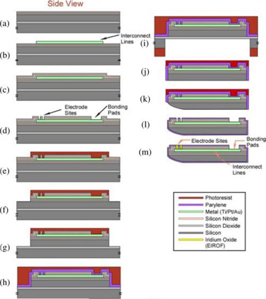
In typical multisite microelectrode arrays, the insulation over the interconnects is only present on the feature plane of the probe, leaving the edges of the device uninsulated and exposed to the saline environment after implantation. This may also expose the uninsulated silicon on the back of the probe [9]. We developed a procedure for encapsulating the entire probe shank with a conformal layer of Parylene C, a United States Pharmacopeia (USP) Class VI material suitable for human implantation (refer to step l of Fig. 3).
Fig. 3.
Process flow chart illustrating major fabrication steps. See the texts for details.
We evaluated our silicon-based microelectrode arrays in vitro and in the central auditory system. The cochlear nucleus (CN) array, for chronic implantation into the cat CN, is comprised of two probes, each with two 2.5 mm shanks, and each shank with four electrode sites measuring 100 μm in thickness. Because the device was custom designed by the authors, the dimension, placement, and spacing of the electrode sites, as well as the thickness, length, and number of the shanks can be reconfigured to meet different experimental needs without relying on a commercial vendor.
II. METHODS
A. Development of Multisite Microelectrodes Arrays
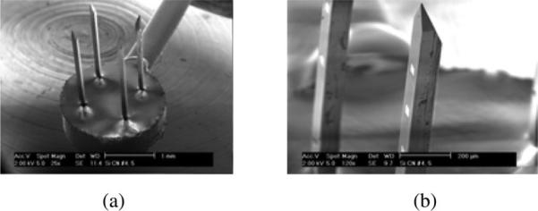
The completed CN array is shown in Fig. 2. The major fabrication steps for the arrays are illustrated in Fig. 3. Briefly, they are elaborated as follows.
On a silicon-on-insulator wafer, the first triple sandwich of silicon dioxide–silicon nitride–silicon dioxide (ONO) is deposited by PECVD.
A bilayer of photoresists is patterned, followed by evaporation and lift-off of titanium, platinum, and gold films, defining the transmission lines, electrodes, and bonding pads.
The second ONO triple sandwich is deposited.
RIE is used to etch the ONO layers to open the recording/stimulating sites and bonding pads.
A thick photoresist layer is spun onto the wafer and patterned to define the shape of the probes.
RIE is used to etch through the ONO layers.
The upper (“device”) silicon wafer is etched by DRIE down to the buried oxide layer, yielding probe profiles of a desired thickness.
A layer of Parylene C is deposited as a protection layer. Another layer of photoresist is then spun onto the device side to bond to a backing wafer (not shown in the drawing) in order to provide mechanical support during the backside DRIE.
Backside DRIE is used to etch up to the buried oxide layer of the wafer.
Following RIE of the oxide layer, individual probes are released from the wafer plane by cutting the holding bars.
The tips of the probes are then shaped by mechanical grinding, reshaping the probe tip from a wedge-like “vertical” edge to a beveled tip. The resulting bevel angle is approximately 20° when viewed from the side.
A 3-μm conformal layer of Parylene C is deposited onto all surfaces (PDS 2010, Specialty Coating Systems) at room temperature and annealed for 24 h at 180 °C under vacuum. The electrode sites and bonding pads are opened using an excimer laser (FTSS266-50, CryLaS, Berlin, Germany), followed by a brief residual cleaning in oxygen plasma at 100 Watt in 250 mTorr (PEIIA, Technics). For assembly into the CN chronic arrays, 0.001” platinum lead wires insulated with Teflon or Parylene C are wedge bonded onto the gold bonding sites, which in turn, are overlaid with MED 4210 silicone elastomer. Two such probes are then placed in a custom Teflon mold with the probe shanks aligned using a custom tool. The mold is filled with a USP V epoxy material (Epotek 301, Epoxy Technologies, Inc., Billerica, MA) to encapsulate the bonding areas. The 16 platinum wires are wound to form a flexible helical cable and are coated with MED 1011 silicone, and the leads are attached to a percutaneous connector.
Finally, iridium oxide is electroplated onto the gold electrode sites to enhance the charge injection capacity [15]. The voltages are cycled between 0 and 625 mV (versus Ag/AgCl) at a rate of 50 mV/s until there is no further increase in the charge storage capacity (CSC), or when CSC reaches 25 mC/cm2.
Fig. 2.
Silicon-based microelectrode arrays developed at HMRI. (a) SEM view of a CN array with a total of four 100-μm-thick shanks and 16 electrode sites. (b) Enlarged view of the tip region of a probe shank showing the sharpened tip and electrode sites on the feature plane.
B. Microelectrode Properties and Characterization
Impedance measurements were obtained using a PC4/300 potentiostat system (Gamry Instruments, Warminster, PA). For in vitro measurements in a phosphate buffered saline (PBS), a three-electrode chemical cell configuration was used with an Ag/AgCl reference electrode, a large carbon counter electrode, and working electrodes. For in vivo measurement, the chemical cell was a large implanted platinum counter electrode, an implanted Ag/AgCl reference electrode, and the array's electrode sites. For the ac impedance measurements, sinusoids from 1 to 100 000 Hz at a level of 10 mV peak to peak were utilized. For cyclic voltammetry (CV) measurement of CSC, a scan rate of 50 mV/s was used [21]. CV is also used before and after the electroplating of iridium oxide film in order to evaluate the effectiveness of the procedure.
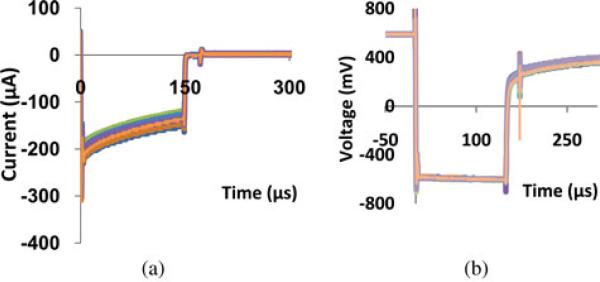
Charge injection capacity Qinj was obtained in PBS and after implantation. Cathodic current pulses of 150 μs was applied to each electrode, riding on an anodic bias of +0.6 V, which increased the charge injection capacity of the EIROFs [15]. The amplitude of the cathodic input current pulse was increased until the output peak voltage (“voltage transient”) reached −0.6 V (and in some cases, −1.2 V) versus Ag/AgCl. The −0.6 V limit is a very conservative estimate of reversible charge injection since a portion of the voltage transient is due to resistive drop in the surrounding medium. Fig. 4 shows an example of the current pulse sequence and the resulting voltage transient. Qinj is calculated, as summarized in Table II, by integrating the charges within the current pulse. The cathodic voltage limits for fully reversible charge injection are ensured by using a “compliance-limited” current stimulator that reduces the stimulus current when the electrode voltage transient attempts to exceed the specified limit [22].
Fig. 4.
Representative charge injection plots of electrodes in one array in PBS. A monophasic cathodic current pulse was injected through the EIROF electrodes (a), while monitoring the resulting voltage (b), which also shows a +0.6 V anodic voltage bias applied to the channel under study. Current pulses of 150 μs in width were used with +0.6 V bias, and cathodic current intensity, in (a), was kept below the resulting potentials of −0.6 V versus Ag/AgCl, at which point Qinj values were obtained. Qinj of EIROF in the PBS was 1.39 ± 0.68 mC/cm2 . When the maximum potential excursion was extended to −1.2 V, its corresponding Qinj was 2.65 ± 1.56 mCm/cm2.
TABLE II.
Charge Injection Capacity of EIROF Microelectrodes, With a +0.6 V Anodic Voltage Bias Versus Ag/AgCl
| Compliance Limit | AVG (mC/cm2) | STD (mC/cm2) | # of electrodes/arrays |
|---|---|---|---|
| PBS | |||
| -0.6V | 1.39 | 0.68 | 56 / 4 |
| -1.2V | 2.65 | 1.56 | 44 / 3 |
| In-Vivo | |||
| -0.6V (2 - 84 weeks) | 0.01 – 0.16 | 0.001-0.07 | 63 / 4 |
| -1.2V (At Week 84) | 0.23 | 0.04 | 13 / 1 |
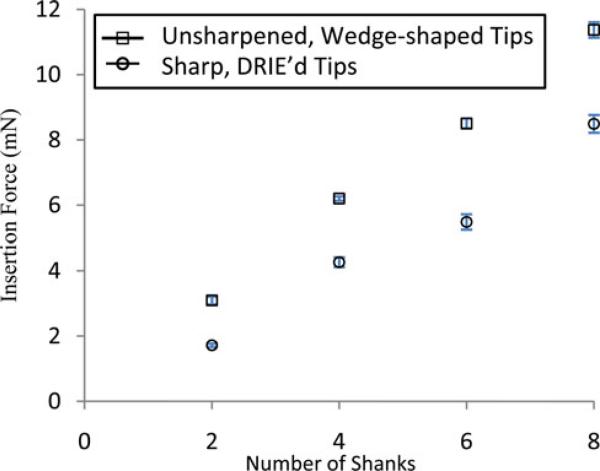
In order to quantify the advantage of shaping the probe tips, we measured insertion forces into the agar by the blunt “wedge” tips [see Fig. 1(a)] and the sharpened tips [see Fig. 1(b)], using arrays with two, four, six, and eight shanks each. The setup is similar to [23] with a load cell (Transducer Techniques, GS0-50) and a constant-speed linear drive system, but is also equipped with a displacement transducer (Measurement Specialties, M12). The arrays were inserted at a speed of 0.9 mm/s into a gel of 2% agar (Fisher Scientific) in water. Labview was used to record all measurements. The data were analyzed in Minitab with a two-way analysis of variances (ANOVA), in which the factors were the number of shanks and the tip shapes (unsharpened or sharpened).
C. Chronic Implantation
The CN arrays were implanted into the feline ventral CN following ethylene oxide sterilization and degassing. The procedure for implanting the array was as described previously [24]. The target location of the array is intended to model a clinical auditory brainstem implant in which an array of penetrating electrodes is inserted into the ventral CN [25].
D. Auditory Physiology Experiment
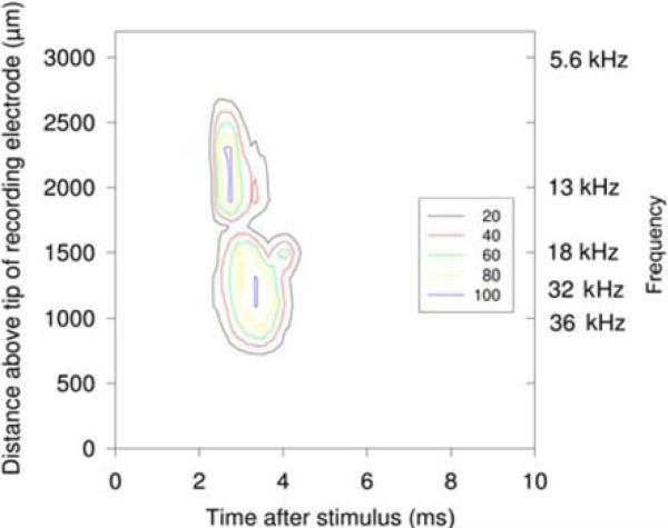
The ability of the chronically implanted CN arrays to access the tonotopic organization of the ventral CN was confirmed by recordings from the inferior colliculus (ICC) in nonrecovery experiments using an “ICC probe” (photos not shown). This probe is a single shank with 16 recording sites, each with a geometrical area of 550 μm2, and was used for acute recording of single- and multiunit activity in the central nucleus of the cat ICC. The shape of the tip region and the rigidity of the DRIE-generated shank allow these long (6 mm) probes to penetrate through the pia membrane covering the cat's ICC without bending or buckling. Other details of the procedures are described in [8]. Briefly, electrical stimulation with controlled-current, stimulus pulses (each pulse with 150 μs in duration, ranging from 0 to 30 μA; 50 pulses per second) was applied to the microelectrode sites in the CN. Poststimulus time histograms, one for each recording site in the ICC response maps, were generated from the histograms, as shown in Fig. 6.
Fig. 6.
Two response maps overlapped, in cat CN172, evoked by a micro-electrode site implanted in the CN for 88 days, that produced a response in the 10 kHz region of the ICC (top contours) and another microelectrode site on an adjacent probe shank in approximately the 30 kHz region (bottom contours). The left ordinate is calibrated in microns above the tip of the multisite recording electrode in the ICC. The calibration based on best responses to acoustic tones is shown on the right ordinate. The contour lines show the multiunit activity as a percentage of the maximum (from 20% to 100%). The stimulation intensity was 30 μA.
E. Analysis and Quantification of Neuronal Recordings
We measured the SNRs of the neuronal action potentials (APs) recorded in the cats’ CN. Data were recorded from all electrically functional electrode sites with the cats lightly anesthetized. The amplitude distribution and the standard deviation (STD) of all peaks were calculated. Events whose amplitude is greater than 3 × STD were omitted from the distribution, and the STD recalculated to yield the mean noise amplitude N. Events with peak amplitude greater than 3 N are classified as neuronal APs. This procedure does not require any assumptions regarding the amplitude distribution of the noise, except that the distribution is unimodal. The overall SNRs of all events classified as AP is computed from the mean of the peak amplitude of all APs. Since this metric is weighted by the S/N of the (more numerous) spikes with lower amplitudes, we also computed the mean SNRs of the 10% of the APs with the largest SNRs as a separate metric.
F. Histology
For the evaluation of neurons and the tissue responses in proximity to the chronically-implanted microelectrode arrays, CN arrays without electrical connections were implanted into the cerebral cortex of adult rabbits: two rabbits for two months and one rabbit for five months. Each array had a silicone cable connected to emulate our intracortical array packaging. The animals were anesthetized and then perfusion-fixed with 4% formaldehyde in phosphate buffer, pH 7.4, immediately following a 100-mL initial perfusion of PBS prewash solution to remove blood from the vasculature. After the arrays were removed from the cortex, the tissue was embedded into paraffin and sectioned at a thickness of 5 μm perpendicular to the lengths of the probe shanks to permit a cross-sectional view of the shank tracks. Tissue sections of cortical layers were evaluated using immunohistochemical markers for neurons (neuronal specific nuclear protein; NeuN) and astrocytes (glial fibrillary acidic protein; GFAP). The sections were treated for 1 h with 20% normal goat serum in PBS. The primary antibodies (NeuN, 1:2000, monoclonal mouse; GFAP, 1:500, polyclonal chicken) were applied. Biotinylated secondary antibodies (antimouse for NeuN and antichicken for GFAP; both at 1:200) were used. The primary and secondary antibodies were diluted in PBS containing 10% normal goat serum. The horseradish peroxidase-based Avidin Biotin Complex kit was used for visualizing the antigen–antibody sites. Nova Red (SK-4800, producing a reddish brown reaction product) was employed for NeuN and SG (SK-4700, producing a bluish black reaction product) for GFAP.
III. RESULTS
A. Electrochemical Properties
AC impedances were first measured in PBS for five CN arrays with a total of 77 electrode sites. The impedance of gold electrodes (surface areas of approximately 2000 μm2) prior to EIROF electrodeposition was uniformly high at 1.58 ± 0.83 MΩ at 1 kHz. Electroplating decreased the impedance to 133 ± 286 kΩ. The CSC of the EIROF microelectrode was more than one order of magnitude greater than that of gold (averages of 20.5 ± 6.9 mC/cm2 versus 1.9 mC/cm2, respectively). Despite some variations between arrays, the overall measurements in PBS confirmed successful electrodeposition of the iridium oxide film. The in vivo impedance values at 1 kHz typically ranged from a few hundred kilohm to below 1 MΩ for the entire duration of implantation of the five arrays.
Table II summarizes charge injection results with different voltage compliance levels and measurement conditions. An example of charge injection capacity Qinj of EIROF is shown in Fig. 4 for Array CN173. In this case, the current levels [see Fig. 4(a)] were selected to limit the maximum potential transient of −0.6 V versus Ag/AgCl [see Fig. 4(b)]. Average Qinj of the EIROF in the PBS was 1.39 ± 0.68 mC/cm2 for 56 electrodes in four arrays tested. When the maximum potential excursion was extended to 1.2 V, the corresponding average Qinj was increased to 2.65 ± 1.56 mC/cm2, as measured from 44 electrodes in three arrays.
After implantation, Qinj of 63 electrodes ranged from 0.01 to 0.16 mC/cm2 with a compliance limit of −0.6 V versus Ag/AgCl and 0.23 ± 0.04 mC/cm2 with a compliance limit of −1.2 V. In one array with 16 electrodes at 84 weeks after implantation, Qinj at −0.6 V was 0.14 ± 0.07 mC/cm2. It should be noted that the ohmic IR drop has not been subtracted from the voltage transients; therefore, all Qinj values presented in this report should be viewed as a conservative measure of the charge injection limit, especially for the values obtained with the −0.6 V compliance limit [21].
B. Mechanical Properties
The insertion force of the arrays into an agar substrate was measured to quantify the advantage of the mechanical shaping of the probe tips (five insertion trials each into a pristine agar surface), and is plotted in Fig. 5. All of the tested groups, from two to eight shank arrays, showed that the sharpened tips resulted in less insertion force than those of the wedge-shaped, unground tips. The two-way ANOVA of the data showed highly significant differences in insertion force for different numbers of shanks and for tip configuration (p < .001 for both effects).
Fig. 5.
Comparison of the insertion forces of sharpened and unsharpened probes into an agar substrate. The sharpened tips yielded lower insertion forces than those of the wedge-tip probes for arrays with two, four, six, and eight shanks. The arrays were assembled similarly to Fig. 2(a). The center-to-center spacing of the shanks was 1 mm. Error bars represent two STDs over five insertion trials.
Mechanical robustness of the CN arrays has also been verified in acute and chronic animal studies by insertions into the CN, spinal cord, and cerebral cortex of cats and rabbits (see Table III). The arrays were inserted at a low speed (approximately 1 mm/s) or a high speed (approximately 1 m/s). In all cases, the probes penetrated though the pia mater, and no shanks were fractured. In most cases, there was minimal bleeding from the network of blood vessels on the surface of the brain and spinal cord [26]. In order to penetrate the thick pia covering the feline lumbar spinal cord, a high-speed inserter tool [27] was used. Due to their sharpened tips, the arrays penetrated fully into the targets with little dimpling of the pia.
TABLE III.
Summary of Insertions Performed at Various Targets
| Targets | Number of Array/Insertions | Insertion speed |
|---|---|---|
| Cerebral cortex | 11; 18 | High (~1 m/sec) & low (~1 mm/sec) |
| Spinal cord | 4;10 | High and low |
| Cochlear nucleus | 8; 8 | Low |
C. Auditory Physiology Testing
A total of five CN arrays were implanted into the cochlear nucleus of five cats. On day 88, cat CN172 was used in a terminal experiment in which the responses in the central nucleus of the ICC were recorded as described previously [8]. Fig. 6 shows the time-depth maps of the responses evoked in the ICC from two microstimulating sites in the contralateral ventral CN. These maps illustrate the precise access to the tonotopic organization of the CN that can be obtained with this type of microstimulating array.
D. Neuronal Recordings and Analysis
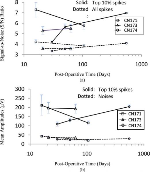
Although the electrodes in the CN are intended primarily for stimulation, and thus have relatively large geometrical areas (~2000 μm2), most sites recorded spontaneous single- and/or multiunit neuronal activities. An example is shown in Fig. 7, where an electrode site in the CN of cat CN174 recorded well-resolved APs at 566 days after implantation. Fig. 8 shows a compilation of long-term recording quality from three arrays, at 16 to 566 days after implantation of the arrays into the cats’ ventral CN.
Fig. 7.
Sample of spontaneous single-unit neuronal activity recordings from an electrode site in a cat's CN array at 566 days after implantation.
Fig. 8.
Summary plots of long-term recording quality from three arrays, recorded from 16 days to 566 days after implantation into the cats’ ventral CN. (a) SNRs of all neuronal units (dotted line) and those of the top 10% of units with the largest SNRs (solid). (b) Mean amplitudes of top 10% units (solid) and of the noises (dotted line). Error bars represent one STD.
E. Histology
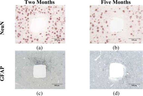
The NeuN- and GFAP-stained rabbits sections are shown in Figs. 9 and 10. In two months, some polarized astrogliosis, as revealed by increased expression of GFAP adjacent to one side of the probe shank, were present around the tracks [see (Fig. 10(c)], but were decreased by five months [see Fig. 10(d)]. Neurons were visible within 50 μm of the edge of the probe tracks. Overall, these cross-sectional views of the silicon shank tracks showed typical medium- and long-term tissue responses to chronic implantation of rigid silicon probes [28].
Fig. 9.
Low-magnification micrograph of NeuN-stained section showing the four silicon shank tracks and a nonuniform distribution of the neurons around the tracks two months after implantation into the cerebral cortex of a rabbit. The array used was similar to the one shown in Fig. 2(a). The sections were cut perpendicular to the axis of the shanks.
Fig. 10.
Histologic sections of rabbit cerebral cortical tissues showing tissue response at different times after implantation. (a) and (b) NeuN stain for neurons. (c) and (d) GFAP stain for astrocytes and their processes. The tissues were sectioned perpendicular to the length of probe shanks after the arrays were removed from the tissue. (a) and (c) Two months after implantation. Astrogliosis is visible mostly near one side of the track. (b) and (d) Five months after implantation. Astrogliosis is reduced from that occurring at two months.
IV. DISCUSSION
To our knowledge, this is the first report on the potential advantages of shaping the tip region of a thick silicon probe using postwafer mechanical grinding. Neither wet nor drying etching alone could provide such flexibility in controlling the shape of the probe tip. The mechanical robustness of the chronic probes, formed by DRIE, has been apparent during the in-wafer fabrication, fabrication of the implantable arrays, insertion into the brain and spinal cord, and explantation after sacrifice of the animal subjects. We believe that the use of DRIE-based thick silicon shanks coupled with post-wafer tip shaping of the tips will render these devices practical for insertions through the thicker pia covering the human brain and spinal cord.
The conformal coating of Parylene C over the entire probe shanks of silicon-based multisite microelectrode arrays offers several advantages, as discussed in Section I: (1) it rounds off the edges of the probe tips and sides, potentially reducing tissue damage during insertion [13], (2) it provides additional electrical insulation for the ONO layers that will cover any defects of the silicon dioxide–silicon nitride–silicon dioxide (ONO) insulation stack on the probes’ feature plane, and in particular, prevents the entrance of electrolytes from the edges of the feature plane, where all six ONO layers would be subject to prolonged exposure to a saline environment, and (3) it encapsulates the probe within a coating having well-established biocompatibility properties. Without the Parylene C coating, the sides and back of the silicon shanks would expose the tissue to the doped silicon, which does not have Food and Drug Administration approval for long-term implantation into the human body.
We deposited ONO layers using a PECVD process, which does not preclude the use of commonly used metals (e.g., gold, titanium, platinum) unlike the LPCVD-based films for which high temperature is required [29]. The use of high conductivity metal such as gold for the conductor traces reduces impedances and driving voltages during stimulation compared to polysilicon [29]. We have shown through chronic implantation into the brain that high-quality PECVD films can be an adequate insulation material that can last for many months in vivo. This also allows the use of EIROF, which is conveniently electroplated onto the gold seed layer. Additionally, for one array tested, we found no noticeable change in impedance or charge transfer density of EIROF electrodes before and after sterilization with ethylene oxide.
There are two main advantages of utilizing compliance voltage limits during current injection. The first is based on the observation that there is always variability in the amplitude of the voltage transient for different electrode sites, both within and across arrays, and over time for individual electrode sites. Coupled with varying “access voltage” (which is attributed to the resistive medial surrounding the implanted electrode), one would have the burden of identifying for each electrode, and at any given time, the amount of stimulus current that can be injected by completely reversible electrochemical processes. The exact definition of access voltage may be subjective. The use of compliance limits ensures that the stimulus charge is injected by reversible electrochemical processes, although a recent report showed that such a condition did not preclude neuronal loss during chronic microstimulation using microwire arrays [30]. Also, excessively large current pulses may cause irreversible damage to the electrode materials (personal observation). An advantage in terms of power consumption in very large scale integration implementation has been discussed [31], and a hardware approach to provide safe stimulation has been demonstrated [32].
The charge injection capacity Qinj of the electroplated iridium oxide obtained in PBS, as reported here, is comparable to those of activated iridium oxide film on silicon substrate [33] and on microwires [34]. However, there are little data available in the literature with which we can compare our in vivo Qinj values obtained up to 84 weeks after device implantation. Weiland and Anderson reported an estimated value based on CSC [35]. A short-term two-week evaluation of poly(3,4-ethylenedioxythiophene) (PEDOT) showed values larger than those of platinum iridium electrodes [36], but potential degradation of the PEDOT film was noted, and in vivo Qinj was not reported. The reasons for the disparities between the CSC versus Qinj, as well as in vitro versus in vivo properties of stimulating electrodes, have been explained in [21]. We hope that the values of Qinj reported in this paper will serve as a useful reference for future development of chronically-implanted microstimulating arrays.
The results of long-term recording from Cat CN174 [see Fig. 8(a)] illustrate the potential of our devices for long-term recording of neuronal activity as well as for long-term micros-timulation. However, the reduction in the SNRs and signal amplitudes in CN171 indicates that the neuronal environment and tissue responses near the implant strongly influence chronic recording. This premise is supported by the similarity across arrays and the stability over time of the noise amplitude (see Fig. 8(b), dotted lines), which suggests that the devices themselves retained all or most of their electrical functionality. (Much of the “noises” recorded are in fact unresolved neuronal activity [37].)
A paper discussing in vivo recording quality using multisite silicon electrode arrays is by Vetter et al., using “Michigan-” type probes [28]. Their results are not directly comparable to ours since their electrodes were implanted in the rat cerebral cortex, whereas our data are from the cat ventral CN; the area of their electrodes sites was 312 μm2 or less, whereas ours were 2000 μm2 (primarily intended for microstimulation). Their mean SNRs of all spikes were 5–9 versus 3–4.5 for ours (4– 8 for the 10% of spikes with the largest SNRs). Their mean signal amplitudes ranged from 50 to 100 μV, versus our 100 to 250 μV for the top 10% of recorded spikes). We recorded for a longer duration (566 days versus 127 days). Ward et al. also reported in vivo recording quality using multisite ceramic and silicon devices, but were able to record APs only for 31 days [38]. During the period, their SNRs ranged from 5–7; signal amplitudes 60–400 μV. Their electrode areas were 1250 μm2 and 1760 μm2, respectively. In general, we can conclude that the ability of our device to record multiunit neuronal activity is comparable to what has been reported for similar electrodes in terms of SNRs and signal amplitudes, even considering our larger electrode site area. It also illustrates that electrodes with a surface area of 2000 μm2 are suitable for both chronic recording and stimulation, which is a valuable asset for some applications.
As shown in Fig. 5, the difference between the insertion forces of the sharpened and unsharpened shanks increased with the number of shanks. While we would not expect the insertion force into the agar gel to be quantitatively representative of those encountered during insertion through the pia mater of various animal subjects or human patients, they do illustrate the advantage of the sharpened tips. One advantage of reduced insertion force during passage through the pia mater and then through the brain parenchyma is less mechanical distortion (strain) within the parenchyma [12].
The tissue response to silicon probes with a boron-doped back surface has been previously shown to produce tissue responses and neuronal loss that are confined to the immediate vicinity of the probes, and in that sense, can be considered to be biocompatible [39, 40]. In this study, the tissue responses to our Parylene C-coated, DRIE-based arrays were investigated after implantation for two to five months. All chronic tissue responses were limited to a localized repair process with a glial sheath formed around the probe shank tracks. This is believed to be the first tissue response study with DRIE-based silicon probes with a conformal coating of Parylene C over the entire probe shanks.
V. CONCLUSION
We have fabricated and validated silicon-based chronicallyimplantable multisite neural probe arrays with a unique combination of features: DRIE-based thick and mechanically sturdy shanks, mechanically ground true 3-D tips, and a conformal coating of Parylene C over the entire probe shanks. The overall insulation quality of the chronic device allowed all five chronically-implanted devices to be fully functional at least for several months. The functionality of the chronic array has been validated for both microstimulation and neural recording. Histologic analyses of the tissue adjacent to the DRIE-processed shanks of the chronically implanted arrays showed only a localized inflammation around the probe shanks. We expect that this probe system will prove valuable in basic neuroscience research, and with further development, may be used clinically in neural prostheses and neuromodulation.
ACKNOWLEDGMENT
The authors would like to thank Y. Smirnova for data acquisition, L. Bullara, V. Cheng, N. Kuleviciute, and Al Kowalewski for device assembly, J. Chavez and C. Graham for histologic tissue processing, V. Pikov for writing software for recording of neural activity and for a semiautomated laser stage, E. Smith, F. Sanchez, and J. Lemke for animal surgery and care, P. Troyk for the compliance-limited current source, and S. Cogan for his help with the EIROF process. The animal use procedures followed the guidelines of the Institutional Animal Care and Use Committee, Huntington Medical Research Institutes, Pasadena, CA, and the National Research Council's Guide for the Care and Use of Laboratory Animals.
This work was supported by the National Institutes of Health under Award R01DC009643 (D. B. McCreery) and Award R21EB008582 (M. Han).
Biography
 Martin Han (M'04) received the B.S. degree in electrical engineering from the University of Hawaii, Honolulu, HI, in 1996, and the M.S. degree in electrical engineering and the Ph.D. degree in biomedical engineering from the University of Southern California, Los Angeles, CA, in 2000 and 2003, respectively. His Ph.D. thesis focused on the development of planar microelectrode arrays for recording and stimulation in hippocampal tissue slices for cognitive prosthesis.
Since 2003, he has been a Staff Scientist in the Neural Engineering Program at Huntington Medical Research Institutes (HMRI), Pasadena, CA, and is a voluntary faculty member with the Department of Ophthalmology, Keck School of Medicine, University of Southern California. His current research interests include the development of silicon- and biodegradable-polymer-based implantable microelectrode arrays using biomicroelectromechanical systems and hybrid microfabrication technologies for better understanding of the brain–device interface and for treating neurological disorders such as profound hearing loss, Parkinson's disease, and spinal cord injury.
Dr. Han is a member of the Eta Kappa Nu, IEEE Engineering in Medicine and Biology Society, Biomedical Engineering Society, Society for Neuroscience, and American Association for the Advancement of Science.
 Panya S. Manoonkitiwongsa received the Ph.D. degree in anatomy from the Department of Pathology and Human Anatomy, School of Medicine, Loma Linda University, Loma Linda, CA, in 1997.
He was a Postdoctoral Fellow in Neurohistology And Histochemistry at Loma Linda University, for one year. He was also a Postdoctoral Fellow in Neuropathology And Quantitative Electron Microscopy in the Departments of Neurosciences and Neurology, and Stroke Research Center, University of California, San Diego, CA, for two years. He was also an Ad junct Professor of Biology in the Department of Life Sciences, San Bernardino Valley College, San Bernardino, CA. Since 2001, he has been with Huntington Medical Research Institutes (HMRI), Pasadena, CA, where he is currently the Chief of Histology, Neuroanatomy and Experimental Neuropathology, and the Director of the Transmission and Scanning Electron Microscopy, Histotechnology, Immunohistochemistry and Image Analysis Laboratories of the Neural Engineering Program. Since 1987, he has also been a board certified in electron microscopy, Microscopy Society of America, Chicago, IL. His research interests include the development of safe and effective neuroprotection-based treatments for ischemic stroke, including therapeutic angiogenesis, and improvements in preclinical study designs for histopathology-based safety neuropharmacology.
Dr. Manoonkitiwongsa is a member of the American Association of Anatomists, National Society for Histotechnology, and Microscopy Society of America.
Cindy X. Wang is currently working toward the B.S. degree in mechanical engineering at the University of California, Berkeley, CA.
From May to August 2011, she was a part of the summer student program in Neural Engineering Program at the Huntington Medical Institute, Pasadena, CA, where she was involved in the development of neural microelectrode arrays. Since September 2011, she has been working as a medical image analyst intern for O. N. Diagnostics, Berkeley, where she is involved in the analysis of CT scans used in osteoporosis applications.
 Douglas B. McCreery received the B.Sc. and M.Sc. degrees in electrical engineering and the Ph.D. degree in biomedical engineering from the University of Connecticut, Storrs, in 1966, 1970, and 1975, respectively.
He was a Postdoctoral Researcher in the Department of Neurosurgery, University of Minnesota, Morris. He is currently the Director of the Neural Engineering Program at Huntington Medical Research Institutes, Pasadena, CA. His research interests include the development of neuroprostheses and devices for neuromodulation for the central nervous system, and the physiologic and histologic effects of electrical stimulation of the central and peripheral nervous systems.
Contributor Information
Martin Han, Huntington Medical Research Institutes, Pasadena, CA 91105 USA (martinhan@hmri.org)..
Panya S. Manoonkitiwongsa, Huntington Medical Research Institutes, Pasadena, CA 91105 USA (stevemanoon@hotmail.com).
Cindy X. Wang, Department of Mechanical Engineering, University of California, Berkeley, CA 94710 USA (cindyx7w@gmail.com).
Douglas B. McCreery, Huntington Medical Research Institutes, Pasadena, CA 91105 USA (dougmc@hmri.org).
References
- 1.Blanche TJ, Spacek MA, Hetke JF, et al. Polytrodes: High-density silicon electrode arrays for large-scale multiunit recording. J. Neurophysiol. 2005;93(5):2987–3000. doi: 10.1152/jn.01023.2004. [DOI] [PubMed] [Google Scholar]
- 2.Yoon TH, Hwang EJ, Shin DY, et al. A micromachined silicon depth probe for multichannel neural recording. IEEE Trans. Biomed. Eng. 2000 Aug.47(8):1082–1087. doi: 10.1109/10.855936. [DOI] [PubMed] [Google Scholar]
- 3.Kindlundh M, Norlin P, Hofmann UG. A neural probe process enabling variable electrode configurations. Sens. Actuators B, Chem. 2004;102(1):51–58. [Google Scholar]
- 4.Moxon KA, Leiser SC, Gerhardt GA, et al. Ceramic-based multisite electrode arrays for chronic single-neuron recording. IEEE Trans. Biomed. Eng. 2004;51(4):647–656. doi: 10.1109/TBME.2003.821037. Apr. [DOI] [PubMed] [Google Scholar]
- 5.Motta PS, Judy JW. Multielectrode microprobes for deep-brain stimulation fabricated with a customizable 3-D electroplating process. IEEE Trans. Biomed. Eng. 2005;52(5):923–933. doi: 10.1109/TBME.2005.845225. May. [DOI] [PubMed] [Google Scholar]
- 6.Han M, Bullara LA, McCreery DB. Development of a robust chronic neural probe. presented at the Biomed. Eng. Soc. Ann. Fall Meet.; Los Angeles, CA. Sep. 26–29, 2007. [Google Scholar]
- 7.Han M, McCreery DB. A new chronic neural probe with electro-plated iridium oxide electrodes. presented at the 30th Annu. Int. Conf. IEEE Eng. Med. Biol. Soc.; Vancouver, BC, Canada. Aug. 20–25, 2008; [DOI] [PubMed] [Google Scholar]
- 8.McCreery DB, Han M, Pikov V. Neuronal activity evoked in the inferior colliculus of the cat by surface macroelectrodes and penetrating microelectrodes implanted in the cochlear nucleus. IEEE Trans. Biomed. Eng. 2010 Jul.57(7):1765–1773. doi: 10.1109/TBME.2010.2046169. [DOI] [PMC free article] [PubMed] [Google Scholar]
- 9.Wise KD, Anderson DJ, Hetke JF, et al. Wireless implantable microsystems: High-density electronic interfaces to the nervous system. Proc IEEE. 2004 Jan.92(1):76–97. [Google Scholar]
- 10.Najafi K, Hetke JF. Strength characterization of silicon microprobes in neurophysiological tissues. IEEE Trans. Biomed. Eng. 1990 May;37(5):474–481. doi: 10.1109/10.55638. [DOI] [PubMed] [Google Scholar]
- 11.Norlin P, Kindlundh M, Mouroux A, et al. A 32-site neural recording probe fabricated by DRIE of SOI substrates. J. Micromech. Microeng. 2002;12(4):414–419. [Google Scholar]
- 12.Bjornsson CS, Oh SJ, Al-Kofahi YA, et al. Effects of insertion conditions on tissue strain and vascular damage during neuroprosthetic device insertion. J. Neural Eng. 2006;3:196–207. doi: 10.1088/1741-2560/3/3/002. [DOI] [PubMed] [Google Scholar]
- 13.Edell DJ, Toi VV, McNeil VM, et al. Factors influencing the bio-compatibility of insertable silicon microshafts in cerebral cortex. IEEE Trans. Biomed. Eng. 1992 Jun.39(6):635–643. doi: 10.1109/10.141202. [DOI] [PubMed] [Google Scholar]
- 14.Jensen W, Yoshida K, Hofmann UG. In-vivo implant mechanics of flexible, silicon-based ACREO microelectrode arrays in rat cerebral cortex. IEEE Trans. Biomed. Eng. 2006 May;53(5):934–940. doi: 10.1109/TBME.2006.872824. [DOI] [PubMed] [Google Scholar]
- 15.Meyer RD, Cogan SF, Nguyen TH, et al. Electrodeposited iridium oxide for neural stimulation and recording electrodes. IEEE Trans. Neural Syst. Rehabil. Eng. 2001 Mar.9(1):2–11. doi: 10.1109/7333.918271. [DOI] [PubMed] [Google Scholar]
- 16.Kovacs GTA, Maluf NI, Petersen KE. Bulk micromachining of silicon. Proc. IEEE. 1998 Aug.86(8):1536–1551. [Google Scholar]
- 17.Wise KD, Angell JB, Starr A. An integrated-circuit approach to extracellular microelectrodes. IEEE Trans. Biomed. Eng. 1970 Jul.17(3):238–247. doi: 10.1109/tbme.1970.4502738. [DOI] [PubMed] [Google Scholar]
- 18.Bean KE. Anisotropic etching of silicon. IEEE Trans. Electron. Devices. 1978 Oct.25(10):1185–1193. [Google Scholar]
- 19.Merlos A, Acero M, Bao MH, et al. TMAH/IPA anisotropic etching characteristics. Sens. Actuators A, Phys. 1993;37–38:737–743. [Google Scholar]
- 20.Turner JN, Shain W, Szarowski DH, et al. Cerebral astrocyte response to micromachined silicon implants. Exp. Neurology. 1999;156:33–49. doi: 10.1006/exnr.1998.6983. [DOI] [PubMed] [Google Scholar]
- 21.Cogan SR. Neural stimulation and recording electrodes. Annu. Rev. Biomed. Eng. 2008;10:275–309. doi: 10.1146/annurev.bioeng.10.061807.160518. [DOI] [PubMed] [Google Scholar]
- 22.Troyk PR, Detlefsen DEA, DeMichele GAD. A multifunctional neural electrode stimulation ASIC using neurotalk interface. Proc. 28th Annu. Int. Conf. IEEE Eng. Med. Biol. Soc.; Aug. 30–Sept. 3,, 2006; pp. 2994–2997. [DOI] [PubMed] [Google Scholar]
- 23.Sharp AA, Ortega AM, Restrepo D, et al. In vivo penetration mechanics and mechanical properties of mouse brain tissue at micrometer scales. IEEE Trans. Biomed. Eng. 2009 Jan.56(1):45–53. doi: 10.1109/TBME.2008.2003261. [DOI] [PMC free article] [PubMed] [Google Scholar]
- 24.McCreery D, Lossinsky A, Pikov V. Performance of multisite silicon microprobes implanted chronically in the ventral cochlear nucleus of the cat. IEEE Trans. Biomed. Eng. 2007 Jun.54(6):1042–1052. doi: 10.1109/TBME.2007.891167. [DOI] [PubMed] [Google Scholar]
- 25.Otto SR, Shannon RV, Wilkinson EP, et al. Audiologic outcomes with the penetrating electrode auditory brainstem implant. Otology Neurotology. 2008;29(8):1147–1154. doi: 10.1097/MAO.0b013e31818becb4. [DOI] [PubMed] [Google Scholar]
- 26.Pikov V. Clinical applications of intraspinal microstimulation. Proc. IEEE. 2008 Jul.96(7):1120–1128. [Google Scholar]
- 27.McCreery D, Pikov V, Lossinsky A, et al. Arrays for chronic functional micro stimulation of the lumbosacral spinal cord. IEEE Trans. Neural. Syst. Rehabil. Eng. 2004 Jun.12(2):195–207. doi: 10.1109/TNSRE.2004.827223. [DOI] [PubMed] [Google Scholar]
- 28.Vetter RJ, Williams JC, Hetke JF, et al. Chronic neural recording using silicon-substrate microelectrode arrays implanted in cerebral cortex. IEEE Trans. Biomed. Eng. 2004 Jun.51(6):896–904. doi: 10.1109/TBME.2004.826680. [DOI] [PubMed] [Google Scholar]
- 29.Wise KD, Sodagar AM, Yao Y, et al. Microelectrodes, microelectronics, and implantable neural microsystems. Proc. IEEE. 2008 Jul.96(7):1184–1202. [Google Scholar]
- 30.McCreery D, Pikov V, Troyk PR. Neuronal loss due to prolonged controlled-current stimulation with chronically implanted microelectrodes in the cat cerebral cortex. J. Neural Eng. 2010;7(3):9. doi: 10.1088/1741-2560/7/3/036005. DOI: 10.1088/1741-2560/73/036005. [DOI] [PMC free article] [PubMed] [Google Scholar]
- 31.Halpern ME, Fallon J. Current waveforms for neural stimulation-charge delivery with reduced maximum electrode voltage. IEEE Trans. Biomed. Eng. 2010 Sep.57(9):2304–2312. doi: 10.1109/TBME.2010.2053203. [DOI] [PubMed] [Google Scholar]
- 32.Schuettler M, Franke M, Krueger TB, et al. A voltage-controlled current source with regulated electrode bias-voltage for safe neural stimulation. J. Neurosci. Methods. 2008;171(2):248–252. doi: 10.1016/j.jneumeth.2008.03.016. [DOI] [PubMed] [Google Scholar]
- 33.Weiland JD, Anderson DJ, Humayun MS. In-vitro electrical properties for iridium oxide versus titanium nitride stimulating electrodes. IEEE Trans. Biomed. Eng. 2002 Dec.49(12):1574–1579. doi: 10.1109/TBME.2002.805487. [DOI] [PubMed] [Google Scholar]
- 34.Cogan SF, Troyk PR, Ehrlich J, et al. Potential-biased, asymmetric waveforms for charge-injection with activated iridium oxide (AIROF) neural stimulation electrodes. IEEE Trans. Biomed. Eng. 2006 Feb.53(2):327–332. doi: 10.1109/TBME.2005.862572. [DOI] [PubMed] [Google Scholar]
- 35.Weiland JD, Anderson DJ. Chronic neural stimulation with thin-film, iridium oxide electrodes. IEEE Trans. Biomed. Eng. 2000 Jul.47(7):911–918. doi: 10.1109/10.846685. [DOI] [PubMed] [Google Scholar]
- 36.Venkatraman S, Hendricks J, King ZA, et al. In vitro and in vivo evaluation of PEDOT microelectrodes for neural stimulation and recording. IEEE Trans. Neural Syst. Rehabil. Eng. 2011 Jun.19(3):307–316. doi: 10.1109/TNSRE.2011.2109399. [DOI] [PubMed] [Google Scholar]
- 37.Gerstein GL. Cross-correlation measures of unresolved multi-neuron recordings. J. Neurosci. Methods. 2000;100(1–2):41–51. doi: 10.1016/s0165-0270(00)00226-0. [DOI] [PubMed] [Google Scholar]
- 38.Ward MP, Rajdev P, Ellison C, et al. Toward a comparison of microelectrodes for acute and chronic recordings. Brain Res. 2009;1282:183–200. doi: 10.1016/j.brainres.2009.05.052. [DOI] [PubMed] [Google Scholar]
- 39.Biran R, Martin DC, Tresco PA. Neuronal cell loss accompanies the brain tissue response to chronically implanted silicon microelectrode arrays. Exp. Neurol. 2005;195(1):115–126. doi: 10.1016/j.expneurol.2005.04.020. [DOI] [PubMed] [Google Scholar]
- 40.Szarowski DH, Andersen MD, Retterer S, et al. Brain responses to micro-machined silicon devices. Brain Res. 2003;983:23–35. doi: 10.1016/s0006-8993(03)03023-3. [DOI] [PubMed] [Google Scholar]


