

Abstract
Background and Objectives
Photothermal therapies have limited efficacy and application due to the poor penetration depth of light inside tissue. In earlier work, we described the development of novel fiberoptic microneedles to provide a means to mechanically penetrate dermal tissue and deliver light directly into a localized target area. This paper presents an alternate fiberoptic microneedle design with the capability of delivering more diffuse, but therapeutically useful photothermal energy. Laser lipolysis is envisioned as a future clinical application for this design.
Materials and Methods
A novel fiberoptic microneedle was developed using hydrofluoric acid etching of optical fiber to permit diffuse optical delivery. Microneedles etched for 10, 30, and 50 minutes, and an optical fiber control were compared with three techniques. First, red light delivery from the microneedles was evaluated by imaging the reflectance of the light from a white paper. Second, spatial temperature distribution of the paper in response to near-IR light (1064 nm, 1 W CW) was recorded using infrared thermography. Third, ex vivo adipose tissue response during 1064 nm, (5 W CW) irradiation was recorded with bright field microscopy.
Results
The acid etching exposed a 3 mm length of the fiber core, allowing circumferential delivery of light along this length. Increasing etching time decreased microneedle diameter, resulting in increased uniformity of red and 1064 nm light delivery along the microneedle axis. For equivalent total energy delivery, thinner microneedles reduced carbonization in the adipose tissue experiments.
Conclusions
We developed novel microscale optical diffusers that provided a more homogeneous light distribution from their surfaces, and compared performance to a flat-cleaved fiber, a device currently utilized in clinical practice. These fiberoptic microneedles can potentially enhance clinical laser procedures by providing direct delivery of diffuse light to target chromophores, while minimizing undesirable photothermal damage in adjacent, non-target tissue.
Keywords: Liquefaction, adipose, lipolysis, laser, carbonization, fat, etching, silica, thermography
Introduction
Focused or near-collimated light only travels a few millimeters into turbid tissues, due to the combined effects of photon scattering and absorption. Many laser cosmetic procedures, such as laser lipolysis and hair removal [1,2], have limited efficacy and restricted uses, due to the short penetration depth of light into skin and underlying tissue [3]. Other potential applications, such as treatment/ablation of skin tumors, are similarly limited by this obstacle [4,5]. Therefore light-guiding optical fibers with flat end faces are commonly used to deliver visible and near-infrared light interstitially to deeper tissue regions [2,6,7]. However, an optical fiber with a flat end face limits the laser power that can be delivered safely because high irradiance at the tip leads to excessive temperature elevation, causing both carbonization of the tissue and thermal damage to the fiber itself.
To deliver increased amounts of therapeutically-useful energy to large tissue regions, several types of optical diffusers have been developed [8-11]. These optical diffusers provided uniform delivery of light from their surfaces for photothermal and photochemical laser therapy procedures [12]. Even though the radiant emittance profile can be well-controlled at the surface of the diffuser, the fluence distribution inside the tissue is determined by inherent tissue optical properties, limiting the volume of tissue that can be treated with a single diffuser. Multiple diffusers have been shown to deliver effective levels of laser energy to larger tissue volumes [13].
Recently, we developed skin penetrating fiberoptic microneedles for delivering laser light to subdermal tissue. These microneedles cause minimal mechanical damage to the dermal tissue they traverse (PCT/US2010/025809) [14]. These microneedles were manufactured using a novel melt-drawing technique to have extremely small diameter (73 to 125 μm) and ultra-sharp tips (≤ 8 μm). Microneedles of these diameters minimize mechanical damage to the healthy tissue, reduce blood loss, and thus afford greater patient comfort [15-17]. Sharp tips lowered the insertion force needed to penetrate the skin, similar to the working principle of a mosquito’s fascicle [18]. Melt-drawn microneedles emitted light only in close proximity to their distal tips, due to the cladding on their exterior surface. Silica fibers with a lower refractive index cladding allow conduction of light along the fiber core through the principal of total internal reflection. These melt-drawn microneedles were more suitable for point delivery rather than diffuse delivery of laser light.
In this paper, we present a new microneedle design that delivers light circumferentially along an acid-etched (cladding removed) length of 3 mm, functioning as a microscale optical diffuser for laser therapy procedures. Light delivery was evaluated with three sets of experiments: 1) photographic imaging of visible red light (wavelength, λ = 635–650 nm) delivery onto white paper, 2) thermal imaging of white paper irradiated with 1064 nm CW light, and 3) microscopic imaging of adipose tissue irradiated with 1064 nm CW light. Excised porcine subdermal fat was used as a relevant translational model for demonstrating laser lipolysis, a potential clinical application for this tool. A flat-cleaved fiber (control) was used for comparison measurements due to the simplicity of its design and significant clinical use for mainstream laser therapy procedures [2,6,7,13,19,20].
Materials and Methods
Manufacturing of fiberoptic microneedles by etching
To fabricate microneedles for this study, we developed a novel manufacturing process using acid etching, to remove cladding and core material from a multimode silica optical fiber with 105 μm core diameter and 125 μm cladding diameter, (AFS105/125Y, Fiber Guide Industries, New Jersey). This multimode substrate fiber is suited for transmitting 1064 nm laser light. In Step I (see Figure 1, below), the optical fiber was flat-cleaved at both ends to approximately 50 cm in length In Step II, one end of the fiber was housed in a capillary tube with 3 mm of fiber extending beyond the tube. The remainder of the fiber was then chemically masked inside the tube. In Step III, the fiber was immersed to a depth of 3 mm in a 50% hydrofluoric (HF) acid aqueous solution (Acros Organics, Belgium). Optical fibers were etched for 10, 30, or 50 minutes with N = 3 samples at each time. Etching time was varied to obtain microneedles with substantially different thicknesses. In Step IV, the microneedles were removed from the HF solution and rinsed.
Fig. 1.
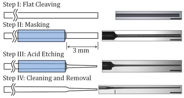
Schematic illustration of the fiberoptic microneedle manufacturing process with a representative image from each step (500 μm scale bar).
Visible light delivery by fiberoptic microneedles
Photographic imaging of visible light delivery has been used to evaluate the emission properties of optical diffusers [11,21,22]. In this study, images of red light delivery were used to qualitatively compare the emission profiles of the different microneedles and the fiber control (Figure 2(a)). A free-space optical coupler (F915-T, Newport, California) was used to launch collimated red light into the microneedles and the fiber control. The distal end (tip) of the fiber control and the microneedles were positioned flat on white paper. Images of the diffusely reflected light from the paper were captured with a digital SLR camera (T1I, Canon USA, New York) attached to a surgical microscope (Revelation, Seiler, Missouri). The images were taken in a dark room, and the same camera exposure settings were used for each image.
Fig. 2.

A schematic representation of microneedle light delivery and specimen interaction experiments (a) Red light delivery/reflectance on white paper (b) 1064 nm light delivery and photothermal response of white paper (c) 1064 nm light delivery and structural response of adipose tissue.
Near-infrared light delivery and photothermal heat generation by fiberoptic microneedles
Near-IR light delivered by fiberoptic microneedles was imaged using infrared thermography. The resultant temperature distribution of paper positioned beneath the microneedles and the fiber control experiments were compared. The region of paper receiving greater intensity of infrared light appeared warmer in thermography images. Continuous wave (CW), 1064 nm light, generated by a diode-pumped fiber laser, (YLR-10-1064-LP, IPG Photonics, Massachusetts) was coupled into the microneedles and the fiber control in the manner described above for visible light delivery experiments (Figure 2(b)). Total power delivered in all directions from each microneedle was measured using an integrating sphere (819C-OPT, Newport, California) with a silicon photodetector (918D-SL-OD1, Newport, California). Microneedles were positioned flat on white paper and a power of P = 1 W was delivered.
A thermal camera (Thermovision A40M, FLIR, Massachusetts) was used to image the temperature distribution around the microneedle and the fiber control during laser irradiation. The emissivity of the white paper (0.9) and the ambient temperature (293 K) were measured and factored into data analysis. The thermal camera was equipped with a focusing lens (Close-up lens LW 34/80, FLIR), and the resulting spatial resolution was 83 μm per pixel. The image-recording rate was 1 Hz.
Microscopic imaging of adipose tissue irradiated with 1064 nm light
Excised porcine abdominal belly skin, from young adult hogs, was acquired from a local abattoir. Subdermal fat specimens of 1-2 mm in thickness were prepared. To maintain hydration prior to the experiments, samples were placed between paper cloths saturated with isotonic saline and maintained at 4 °C. The fiberoptic microneedles were placed on a glass slide, and the fat samples were placed over the microneedles. Fat samples were irradiated with 1064 nm light for 60 seconds with P = 5 W of power delivered by microneedles and the fiber control. Bright field imaging (DM IL LED, Leica Microsystems, Switzerland) was used to capture images of fat liquefaction, which was indicated by the disruption of adipocytes. Carbonization (charring) of the tissue around the microneedles and the fiber control was considered an indication that the local temperature of the tissue/needles exceeded 100 °C [23]. Pre- and post-experimental images of the microneedles were compared and any carbonization of the tissue was noted (Table 1). A schematic illustration of the experimental setup is given in Figure 2(c).
Table 1. Geometric parameters of microneedles.
| Microneedle | Etching Time [Minutes] |
Length [mm] |
Average Thickness [μm] |
Tip Thickness [μm] |
Carbonization Observed? |
|---|---|---|---|---|---|
| Control | N/A | N/A | 125 | 125 | Yes |
| 10-I | 10 | 2.9 | 99 | 92 | Yes |
| 10-II | 10 | 3.0 | 98 | 95 | Yes |
| 10-III | 10 | 3.0 | 97 | 95 | Yes |
| 30-I | 30 | 3.0 | 72 | 59 | Yes |
| 30-II | 30 | 2.7 | 70 | 65 | Yes |
| 30-III | 30 | 2.7 | 68 | 60 | Yes |
| 50-I | 50 | 3.0 | 48 | 21 | No |
| 50-II | 50 | 2.9 | 38 | 20 | No |
| 50-III | 50 | 2.8 | 33 | 17 | Yes |
Results
Microneedle geometrical properties
Representative images from different stages of the manufacturing process are shown in Figure 1. Dimensions of the microneedles were measured from bright field digital images recorded with a microscope. Length, average thickness, and tip thickness are listed for each microneedle in Table 1. The average thickness was calculated by averaging the thickness at the tip and the base. A line in the Step IV image in Figure 1 marks the horizontal location of the microneedle base. In this Table, microneedles are grouped according to their etching time and sequentially numbered.
Visible light delivery by fiberoptic microneedles
Representative red light delivery images of microneedles and the fiber control are shown in Figure 3. The bright field microscopy images of the microneedles and the fiber control are shown beneath each light delivery image with the same position and magnification. For the fiber control, all of the visible light was delivered from the flat end face (Figure 3(a)). Thus, the fiber was not visible in this image. After leaving the tip, the light diverged in a conical beam as theoretically predicted, based on the numerical aperture (NA = 0.22) of the fiber. A representative microneedle is shown for each etching time of 10, 30, and 50 minutes in Figure 3(b), (c), and (d) respectively. For all the microneedles, visible light was emitted from the circumference, rendering them visible. As the etching time was increased, a larger region of diffuse reflection from the underlying white paper was formed around the microneedles, and the area of the spot of saturated intensity near the tip was reduced.
Fig. 3.

Diffuse reflectance of red light from white paper during delivery by (a) Control, (b) 10-I, (c) 30-I, and (d) 50-III (500 μm scale bar).
Near-infrared light delivery and photothermal heat generation by fiberoptic microneedles
The temperature distribution of the paper beneath the microneedles and the fiber control following 15 seconds of irradiation with 1064 nm light (P = 1 W) are shown in Figure 4. The tip of each microneedle and the fiber control were positioned at x = 4 mm and y = 1.5 mm in each image. In Figure 4, the region of higher temperature extended from the tip towards the base of the microneedle as the etching time was increased from zero (Control, Figure 4(a)) to 50 minutes (50-III, Figure 4(d)).
Fig. 4.

Temperature distribution after 15 seconds of irradiation (1064 nm, P = 1 W) for (a) Control, (b) 10-I, (c) 30-I, and (d) 50-III.
To allow quantitative assessment of the 1064 nm light delivery and resultant heat generation in the paper, the local temperature along the axes of the microneedles and the fiber control following 15 seconds of irradiation with 1064 nm light (P = 1 W) are plotted in Figure 5. Axial temperature profiles in Figure 5 demonstrate that as the etching time was increased the light was delivered more uniformly through the length of the microneedles. As a result, while light delivery by the control generated a large temperature peak right in front of the tip (x = 4.1 mm), light delivery by 50-III generated relatively uniform temperatures along the length of the microneedle (x = 1-4 mm).
Fig. 5.
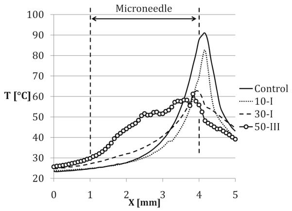
Local temperature along the axes of the microneedles and the control fiber after 15 seconds of Irradiation
Microscopic imaging of adipose tissue irradiated with 1064 nm light
A representative image for light delivery experiments conducted in adipose tissue with the microneedles of different etching times and fiber control are shown in Figure 6. In the pre-irradiation images, (duration of laser irradiation, Δt = 0 s), microneedles and the fiber control were delivering red laser light and individual adipocytes were visible. In these images, microneedle tips are marked with dashed lines.
Fig. 6.
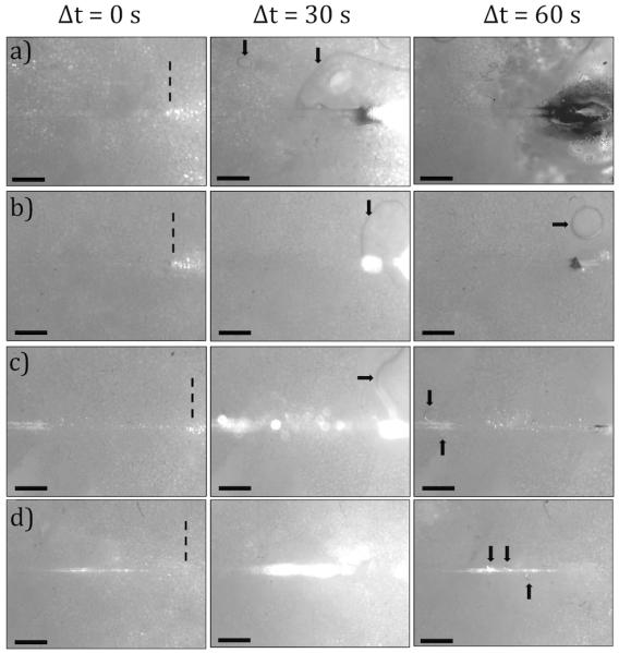
Images of the adipose tissue before, during, and after 1064 nm, P = 5 W irradiation for 60 seconds (a) Control, (b) 10-I, (c) 30-II, (d) 50-I
Images captured during laser irradiation (Δt = 30 s) show microneedles and the fiber control delivering 1064 nm light (P = 5 W), which saturated the camera. Post-experimental images (Δt = 60 s) show disruption of adipocytes and carbonization of the tissue. Pools of liquefied fat (marked by arrows) were observed in all post-experimental images. Decreased microneedle diameter was correlated with decreased incidence of tissue and fiber tip carbonization (Table 1). All of the microneedles were intact following experimentation with the exception of 50-III that was severed at its base.
Discussion
The goal of this study was to develop and test fiberoptic microneedles that diffusely deliver light into tissue. For this purpose, a four-step manufacturing process was developed to controllably etch away the outermost material (cladding) and portions of the core of an optical fiber. This process is uniquely different from our previously published method of melt-drawing the entire fiber, which preserved the cladding and resulted in point delivery of light near the microneedle tip [14]. Etching time was varied between 10 to 50 minutes to obtain microneedles with significantly different diameters (ranging from 33 to 99 μm). Variability in diameter was observed between microneedles with the same etching time. For example, diameters of microneedles 10-I through III ranged from 99 to 97 μm, and 30-I through III varied between 72 to 68 μm. The greatest diameter variation occurred between microneedles 50-I through 50-III (48 to 33 μm). This variation is expected for small-scale manufacture in the laboratory, and may be attributed to experimental uncertainties such as 1) manual placement of the chemical mask on the fiber, 2) depth of acid immersion (3±0.5 mm), 3) time of acid immersion (variation less than 1 min), and 4) innate variations in the substrate fiber used for manufacturing. Manufacturing repeatability and reliability may be improved by simultaneous batch fabrication for potential commercial applications.
Visible light delivery experiments demonstrated that decreasing microneedle thickness correlated with increased diffuse light emission. This is evident in Figure 3, which shows a substantial increase in the area of the reflected light around the microneedles for decreasing diameter. For thinner microneedles, less of the light was delivered in the forward direction, resulting in reduced intensity near the tip. These results indicate that thinner microneedles may be considerably more efficient in delivering diffuse light. This is an attractive area for further investigation.
The qualitative observations obtained from the light delivery images were quantitatively supported by thermal imaging experiments. As the microneedle thickness decreased, more diffuse light delivery resulted in lower maximum temperatures (Figure 4). Microneedles that were etched longer, such as 50-III, generated an increased and more uniform region of heating along their lengths (Figure 5), which may be preferable for many photothermal therapy applications.
Fat irradiation experimental results highlighted several differences between the fiber control and microneedles of different thicknesses. First, the region of disrupted adipocytes shifted away from the tip (Figure 6(a)) and towards the mid-length of the microneedle (Figure 6(d)) as the microneedle thickness decreased. This is expected as more light was emitted prior to the tip with thinner microneedles. Secondly, the amount of carbonized tissue diminished with deceasing thickness. Minimizing carbonization is important, as carbonization of the tissue has detrimental effects on the efficiency of laser photothermal therapy by limiting light propagation inside the tissue and visibility during surgery [23,24]. Carbonized tissue can cover the surface of the microneedle, causing the local temperature around the microneedle to become extremely high, leading to more carbonization, and eventual failure. Mordon et al. reported tissue carbonization as a complication of laser lipolysis with a continuous wave laser (wavelength, λ = 980 nm, P = 15 W) [25]. This carbonization was possibly due to a high irradiance (Ir ~ 53 W/mm2) on the tissue around the 600-μm thick fiber tip.
In our work , the fiberoptic microneedles delivered light through a larger, circumferential surface area as opposed to the flat-cleaved fiber, which delivers light through the smaller, cross-sectional area of its core. The fiber control carbonized the tissue when delivering P = 5 W through its 105 μm diameter core (Ir = 577 W/mm2). In contrast, the light delivery surface area of microneedle 50-II during fat liquefaction experiments was ~0.35 mm2 (obtained by approximating the microneedle as a cylinder). This microneedle was able to deliver P = 5 W with a spatially-averaged irradiance of Ir = 14 W/mm2 without causing any carbonization. Increasing the surface area available for light emission from a microneedle optical diffuser can reduce undesirable effects of high irradiance while still delivering high energy or power dose.
These results indicate that thinner microneedles (33-48 μm) are favorable for light delivery properties. Due to their slenderness, these microneedles can be damaged while being inserted into organs such as skin. In prior work, we were not able to penetrate skin with microneedles that were 70 μm or thinner [14]. In this study, microneedle 50-III was damaged while liquefying fat. Mechanical damage caused the light-diffusing surface to reduce drastically and caused carbonization of the tissue. To address this issue, we are developing a microneedle insertion device, which will mechanically strengthen the microneedles by limiting their unsupported length during insertion into tissue.
Conclusions
We designed novel fiberoptic microneedles that functioned as microscale optical diffusers and provided a more homogeneous light emission from their surfaces compared to a flat-cleaved optical fiber. This permitted more broadly distributed light, in addition to reduced heat generation, and temperature elevation (demonstrated on paper and in adipose tissue), for equivalent total power and energy delivered. The fiberoptic microneedles appear to be particularly well-suited for clinical laser applications that require light to be delivered several millimeters beneath an epithelial surface, such as laser hair removal [7], lipolysis [2,26-29], and treatment of skin and bladder carcinomas [4,5,30,31]. Furthermore, fiberoptic microneedles as we described may be quite useful in experimental laser hyperthermia procedures for cancerous or other lesions in sensitive organs such as the brain, where existing optical diffusers have been shown to be effective in avoiding carbonization, but are more likely to induce mechanical damage due to their larger thickness (>1.5 mm) compared to a bare fiber [32]. Fiberoptic microneedles can potentially be applied in both open surgery and catheterization procedures. Owing to their microscale size, these microneedles induce minimal damage while allowing the laser light to reach several millimeters deeper than laser energy incident on the tissue surface.
Acknowledgements
The authors would like to acknowledge NSF (CBET 0933571) and NIH/NCI (1R21CA156078) for the financial support of this project. The authors also acknowledge the United States Air Force Office of Scientific Research for a travel grant awarded to present this research at the 30th Annual American Society for Lasers Medicine and Surgery and Medicine Conference in Phoenix, Arizona in April 2010.
Footnotes
The authors have no conflicts of interest regarding any information presented in this paper.
Contributor Information
Mehmet A. Kosoglu, Department of Mechanical Engineering, Virginia Tech, Randolph Hall, 100L1, Blacksburg, Virginia, 24061
Robert L. Hood, Virginia Tech-Wake Forest University School of Biomedical Engineering and Sciences, Virginia Tech, ICTAS Bldg, Stanger St, Room 325, Blacksburg, Virginia, 24061, Phone: (361) 563-1613, Fax: (540) 231 0970, robert86@vt.edu
Dr. John H. Rossmeisl, Jr., Virginia Tech, Virginia-Maryland Regional College of Veterinary Medicine, Department of Small Animal Clinical Sciences, Phase II, Room 272, Blacksburg, VA 24061, Phone: (540) 231-3595, jrossmei@vt.edu.
Dr. David C. Grant, Virginia Tech, Virginia-Maryland Regional College of Veterinary Medicine, Department of Small Animal Clinical Sciences, Phase II, Room 306, Blacksburg, VA 24061, Phone: (540) 231-5699s, dgrant@vt.edu.
Dr. Yong Xu, Department of Electrical and Computer Engineering, Virginia Tech, Whittemore, 467, Blacksburg, Virginia, 24061, Phone: (540) 231-2464, Fax: (540) 231-3362, yong@vt.edu
Dr. John L. Robertson, Virginia Tech, Virginia-Maryland Regional College of Veterinary Medicine, Department of Biomedical Sciences & Pathobiology, Phase II, Room 214, Blacksburg, VA 24061, Phone: (540) 231-4643, drbob@vt.edu.
Dr. M. Nichole Rylander, Virginia Tech-Wake Forest University School of Biomedical Engineering and Sciences and Department of Mechanical Engineering, Virginia Tech, ICTAS Bldg, Stanger St, Room 335, Blacksburg, Virginia 24061, Phone: (540) 231-3134, Fax: (540) 231 0970, mnr@vt.edu
Dr. Christopher G. Rylander, Virginia Tech-Wake Forest University School of Biomedical Engineering and Sciences and Department of Mechanical Engineering, Virginia Tech, ICTAS Bldg, Stanger St, Room 325, Blacksburg, Virginia 24061, Phone: (540) 231-0964, Fax: (540) 231 0970, cgr@vt.edu
References
- 1.Wheeland RG. Laser-assisted hair removal. Dermatol Clin. 1997;15(3):469. doi: 10.1016/s0733-8635(05)70455-1. &. [DOI] [PubMed] [Google Scholar]
- 2.Badin AZD, Moraes LM, Gondek L, Chiaratti MG, Canta L. Laser lipolysis: Flaccidity under control. Aesthet Plast Surg. 2002;26(5):335–339. doi: 10.1007/s00266-002-1510-3. [DOI] [PubMed] [Google Scholar]
- 3.Bhatt N, Alster TS. Laser surgery in dark skin. Dermatol Surg. 2008;34(2):184–195. doi: 10.1111/j.1524-4725.2007.34036.x. [DOI] [PubMed] [Google Scholar]
- 4.Gibson SC, Byrne DS, McKay AJ. Ten-year experience of carbon dioxide laser ablation as treatment for cutaneous recurrence of malignant melanoma. Brit J Surg. 2004;91(7):893–895. doi: 10.1002/bjs.4558. [DOI] [PubMed] [Google Scholar]
- 5.Kozlov AP, Moskalik KG. Pulsed Laser-Radiation Therapy of Skin Tumors. Cancer. 1980;46(10):2172–2178. doi: 10.1002/1097-0142(19801115)46:10<2172::aid-cncr2820461013>3.0.co;2-l. [DOI] [PubMed] [Google Scholar]
- 6.Verdaasdonk RM, vanSwol CFP. Laser light delivery systems for medical applications. Phys Med Biol. 1997;42(5):869–894. doi: 10.1088/0031-9155/42/5/010. [DOI] [PubMed] [Google Scholar]
- 7.Hashimoto K, Kogure M, Irwin TL, Tezuka K, Osawa T, Kato K, Ebisawa T. Permanent hair removal with a diode-pumped Nd : YAG laser: A pilot study using the direct insertion method. J Am Acad Dermatol. 2003;49(6):1071–1080. doi: 10.1016/s0190-9622(03)02130-3. [DOI] [PubMed] [Google Scholar]
- 8.Ward H. Molding of Laser Energy by Shaped Optic Fiber Tips. Laser Surg Med. 1987;7(5):405–413. doi: 10.1002/lsm.1900070506. [DOI] [PubMed] [Google Scholar]
- 9.Chang CT, Auth DC. Radiation Characteristics of a Tapered Cylindrical Optical Fiber. J Opt Soc Am. 1978;68(9):1191–1196. [Google Scholar]
- 10.Vesselov L, Whittington W, Lilge L. Design and performance of thin cylindrical diffusers created in Ge-doped multimode optical fibers. Appl Optics. 2005;44(14):2754–2758. doi: 10.1364/ao.44.002754. [DOI] [PubMed] [Google Scholar]
- 11.Small W, Buckley PR, Wilson TS, Loge JM, Maitland KD, Maitland DJ. Fabrication and characterization of cylindrical light diffusers comprised of shape memory polymer. J Biomed Opt. 2008;13(2) doi: 10.1117/1.2904952. [DOI] [PMC free article] [PubMed] [Google Scholar]
- 12.Ripley PM, MacRobert AJ, Mills TN, Bown SG. A comparative optical analysis of cylindrical diffuser fibres for laser therapy using fluorescence imaging. Laser Med Sci. 1999;14(4):257–268. [Google Scholar]
- 13.Haraldsdottir KH, Ivarsson K, Gotberg S, Ingvar C, Stenram U, Tranberg KG. Interstitial laser thermotherapy (ILT) of breast cancer. Ejso-Eur J Surg Onc. 2008;34(7):739, 745. doi: 10.1016/j.ejso.2008.01.008. [DOI] [PubMed] [Google Scholar]
- 14.Kosoglu MA, Hood RL, Chen Y, Xu Y, Rylander MN, Rylander CG. Fiber Optic Microneedles for Transdermal Light Delivery: Ex Vivo Porcine Skin Penetration Experiments. Journal of Biomechanical Engineering. 2010;132(9):091014. doi: 10.1115/1.4002192. [DOI] [PubMed] [Google Scholar]
- 15.Kaushik S, Hord AH, Denson DD, McAllister DV, Smitra S, Allen MG, Prausnitz MR. Lack of pain associated with microfabricated microneedles. Anesth Analg. 2001;92(2):502–504. doi: 10.1097/00000539-200102000-00041. [DOI] [PubMed] [Google Scholar]
- 16.Gill HS, Denson DD, Burris BA, Prausnitz MR. Effect of microneedle design on pain in human volunteers. Clin J Pain. 2008;24(7):585–594. doi: 10.1097/AJP.0b013e31816778f9. [DOI] [PMC free article] [PubMed] [Google Scholar]
- 17.Gill HS, Prausnitz MR. Does Needle Size Matter? J Diabetes Sci Technol. 2007;1(5):725–729. doi: 10.1177/193229680700100517. [DOI] [PMC free article] [PubMed] [Google Scholar]
- 18.Ramasubramanian MK, Barham OM, Swaminathan V. Mechanics of a mosquito bite with applications to microneedle design. Bioinspiration & Biomimetics. 2008;3(4):1–10. doi: 10.1088/1748-3182/3/4/046001. [DOI] [PubMed] [Google Scholar]
- 19.Achauer BM, Celikoz B, VanderKam VM. Intralesional bare fiber laser treatment of hemangioma of infancy. Plast Reconstr Surg. 1998;101(5):1212–1217. doi: 10.1097/00006534-199804050-00006. [DOI] [PubMed] [Google Scholar]
- 20.Lindner U, Lawrentschuk N, Weersink RA, Davidson SRH, Raz O, Hlasny E, Langer DL, Gertner MR, Van der Kwast T, Haider MA, Trachtenberg J. Focal Laser Ablation for Prostate Cancer Followed by Radical Prostatectomy: Validation of Focal Therapy and Imaging Accuracy. Eur Urol. 2010;57(6):1111–1114. doi: 10.1016/j.eururo.2010.03.008. [DOI] [PubMed] [Google Scholar]
- 21.Verdaasdonk RM, Borst C. Ray Tracing of Optically Modified Fiber Tips .1. Spherical Probes. Appl Optics. 1991;30(16):2159–2171. doi: 10.1364/AO.30.002159. [DOI] [PubMed] [Google Scholar]
- 22.Verdaasdonk RM, Borst C. Ray Tracing of Optically Modified Fiber Tips .2. Laser Scalpels. Appl Optics. 1991;30(16):2172–2177. doi: 10.1364/AO.30.002172. [DOI] [PubMed] [Google Scholar]
- 23.Niemz MH. Laser-tissue interactions : fundamentals and applications. xvi. Springer; Berlin ; New York: 2004. p. 305. [Google Scholar]
- 24.Wyman D, Wilson B, Adams K. Dependence of Laser Photocoagulation on Interstitial Delivery Parameters. Laser Surg Med. 1994;14(1):59–64. doi: 10.1002/lsm.1900140113. [DOI] [PubMed] [Google Scholar]
- 25.Mordon S, Eymard-Maurin AFo, Wassmer B, Ringot J. Histologic Evaluation of Laser Lipolysis: Pulsed 1064-nm Nd:YAG Laser Versus CW 980-nm Diode Laser. Aesthetic Surgery Journal. 2007;27(3):263–268. doi: 10.1016/j.asj.2007.03.005. [DOI] [PubMed] [Google Scholar]
- 26.Brown SA, Rohrich RJ, Kenkel J, Young L, Hoopman J, Coimbra M. Effect of low-level laser therapy on abdominal adipocytes before lipoplasty procedures. Plastic and Reconstructive Surgery. 2004;113(6):1796–1804. doi: 10.1097/01.prs.0000117302.73214.1a. [DOI] [PubMed] [Google Scholar]
- 27.Zelickson BD, Dressel TD. Discussion of Laser-Assisted Liposuction. Laser Surg Med. 2009;41(10):709–713. doi: 10.1002/lsm.20842. [DOI] [PubMed] [Google Scholar]
- 28.Reynaud JP, Skibinski M, Wassmer B, Rochon P, Mordon S. Lipolysis Using a 980-nm Diode Laser: A Retrospective Analysis of 534 Procedures. Aesthet Plast Surg. 2009;33(1):28–36. doi: 10.1007/s00266-008-9262-3. [DOI] [PMC free article] [PubMed] [Google Scholar]
- 29.Fisher NM, Schaffer JV, Berwick M, Bolognia JL. Breslow depth of cutaneous melanoma: Impact of factors related to surveillance of the skin, including prior skin biopsies and family history of melanoma. J Am Acad Dermatol. 2005;53(3):393–406. doi: 10.1016/j.jaad.2005.03.004. [DOI] [PubMed] [Google Scholar]
- 30.Syed HA, Biyani CS, Bryan N, Brough SJS, Powell CS. Holmium : YAG laser treatment of recurrent superficial bladder carcinoma: Initial clinical experience. J Endourol. 2001;15(6):625–627. doi: 10.1089/089277901750426427. [DOI] [PubMed] [Google Scholar]
- 31.Pietrow PK, Smith JA. Laser treatment for invasive and noninvasive carcinoma of the bladder. J Endourol. 2001;15(4):415–418. doi: 10.1089/089277901300189466. [DOI] [PubMed] [Google Scholar]
- 32.Atsumi H, Matsumae M, Kaneda M, Muro I, Mamata Y, Komiya T, Tsugu A, Tsugane R. Novel laser system and laser irradiation method reduced the risk of carbonization during laser interstitial thermotherapy: Assessed by MR temperature measurement. Laser Surg Med. 2001;29(2):108–117. doi: 10.1002/lsm.1096. [DOI] [PubMed] [Google Scholar]