Abstract
Bevel-tip steerable needles for minimally invasive medical procedures can be used to reach clinical targets that are behind sensitive or impenetrable areas and are inaccessible to straight, rigid needles. We present a fast algorithm that can compute motion plans for steerable needles to reach targets in complex, 3D environments with obstacles at interactive rates. The fast computation makes this method suitable for online control of the steerable needle based on 3D imaging feedback and allows physicians to interactively edit the planning environment in real-time by adding obstacle definitions as they are discovered or become relevant. We achieve this fast performance by using a Rapidly Exploring Random Tree (RRT) combined with a reachability-guided sampling heuristic to alleviate the sensitivity of the RRT planner to the choice of the distance metric. We also relax the constraint of constant-curvature needle trajectories by relying on duty-cycling to realize bounded-curvature needle trajectories. These characteristics enable us to achieve orders of magnitude speed-up compared to previous approaches; we compute steerable needle motion plans in under 1 second for challenging environments containing complex, polyhedral obstacles and narrow passages.
I. Introduction
Needle insertion is widely-used in minimally invasive medical procedures for diagnosis and treatment, including biopsy sample removal, delivery of drug injections, and radioactive seed implantation for cancer treatment. Performing these procedures using traditional rigid needles is limited to straight-line paths between the needle entry point and target zone, which can lead to complications due to the inability to maneuver around impenetrable or sensitive anatomical structures. As an alternative to rigid needles, a new class of highly flexible, bevel-tip needles are being developed that enable the needle to move along curved trajectories within tissue when a forward pushing force is applied [19], [2]. This class of steerable needles offers improved mobility, enabling needles to reach previously inaccessible targets while maneuvering around sensitive or impenetrable areas.
Planning and executing needle insertion procedures for bevel-tip steerable needles is a difficult problem due to factors such as the nonholonomic motion of the needle tip, the presence of anatomical obstacles, and uncertainty in needle motion and state feedback. For a human operator, navigating a steerable needle under image guidance by manipulating the needle at its base is challenging and would require extensive training and experience. These problems can be alleviated with the assistance of motion planning software for computing feasible needle motions that avoid anatomical obstacles and reach clinical targets.
We present a fast, sampling-based motion planning algorithm capable of computing motion plans at interactive rates for steerable needles in complex, 3D environments with obstacles. This method could potentially be used for online control of the steerable needle based on 3D imaging feedback (obtained from imaging modalities like 3D ultrasound and MRI). It could also allow physicians to interactively edit the planning environment (e.g. relocate the target or add obstacle definitions) and immediately generate new motion plans on the fly as new information is discovered or becomes relevant.
Our approach is based on Rapidly-exploring Random Trees (RRTs) [11] with key extensions and customizations to enable fast motion planning for steerable needles. We use a reachability-guided sampling heuristic that alleviates the sensitivity of the RRT planner to the choice of the distance metric and yields significant improvement in performance of the planner [18]. In contrast to many prior motion planners for steerable needles, we relax the restrictive constraint of constant-curvature needle trajectories by using duty cycling as introduced by Minhas at al. [12], [9] to realize bounded-curvature trajectories.
We illustrate feasible plans computed by our planner in Fig. 1. We also consider a clinically motivated planning objective to evaluate the quality of a path in terms of the needle insertion length (shortest paths) and maximum clearance from the obstacles in the workspace. Prior methods addressing this problem require multiple seconds or minutes to compute a single motion plan [7], [21], [22]; the approach introduced in this paper enables us to achieve orders of magnitude speed-up in computing steerable needle plans through challenging 3D environments with polyhedral obstacles and narrow passages.
Fig. 1.
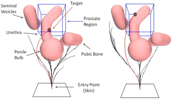
Our interactive-rate motion planner steers a flexible, bevel-tip needle around anatomical obstacles in a scenario modeling the human prostate anatomy (based on Xu et al. [22]). The region of interest (in and around the prostate) is indicated by the blue bounding box. For two different targets, we illustrate the RRT constructed during the planning phase (black) and a feasible trajectory for the needle (highlighted in red).
II. Related Work
Webster et al. [19] developed and experimentally validated a nonholonomic model of bevel-tip, flexible needle motion in stiff tissues and fit model parameters using experiments with tissue phantoms. Other steerable needle designs have also been proposed, including steering symmetric-tip needles by deforming tissues [6], stylet tips [14], and pre-bent tubes [17], [20]. Our emphasis is on bevel-tip, flexible needles, which we refer to simply as steerable needles in this paper.
Motion planning for steerable needles has been extensively studied for 2D environments. Alterovitz et al. modeled the needle motion in 2D as a Dubins car without reverse and used a nonlinear optimization-based planning framework to consider tissue deformation during needle insertion [2]. To consider motion uncertainty due to needle/tissue interaction, Alterovitz et al. formulated the motion planning problem as a Markov Decision Process (MDP) using a regular discretization of space and orientations [1] and using a sampling-based approach based on the Stochastic Motion Roadmap (SMR) [3]. Both these approaches generate a lookup table using dynamic programming that allows for instantaneous image-guided control for the steerable needle in a plane [16]. Scaling these 2D approaches to 3D environments is complicated by the increased dimensionality of the state space and permissible motion space.
With the increased use of volumetric medical imaging techniques such as 3D ultrasound and MRI, it is necessary to consider needle steering in 3D environments. Park et al. [15] proposed a diffusion-based motion planning method to compute steerable needle paths in obstacle-free stiff tissue. Duindam et al. [7] formulated the 3D motion planning problem as an optimization problem by representing the motion of the steerable needle in 3D as a screw motion and discretizing control space. Duindam et al. [8] proposed an inverse kinematics solution to analyze the reachability of the needle tip in obstacle-free environments in both 2D and 3D. Xu et al. [21], [22] used RRTs to (probabilistically) explore the entire state space for computing valid needle paths in 3D environments with obstacles. These approaches are not particularly suited for guiding steerable needles under image-based feedback due to lack of completeness guarantees or slow speed combined with the lack of consideration of uncertainty. Recently, Hauser et al. [10] proposed a method to perform feedback-based control for steerable needles in deformable tissue, but the method cannot compute paths that avoid complex or non-convex obstacles.
In contrast to previous work, we propose a fast, sampling-based motion planning algorithm for steerable needles that enables us to achieve orders of magnitude speed-up in comparison to previous approaches for motion planning in 3D environments with complex obstacles and narrow passages. Our method could be used for interactive control of steerable needles under 3D imaging feedback and allow physicians to interactively edit the environment in real-time by adding obstacles as they are discovered or become relevant.
III. Problem Statement and Assumptions
A. Problem Statement and Objective
Our goal is to guide the tip of a steerable needle to a goal location in the tissue while avoiding anatomical obstacles. We assume we have access to medical images or sensor data that can be used to precisely specify the geometry of the environment ε and the set of obstacle definitions .
The motion of the needle tip is controlled by two inputs: the insertion speed v(t) and the rotational speed of the needle shaft ω(t). The needle bends in the direction of the bevel tip, as has been experimentally shown in [19]. We assume that the kinematic motion model for the needle (as described in detail in Sec. III-B) is completely deterministic and do not explicitly consider uncertainty due to tissue inhomogeneity and tissue deformation. This does not preclude re-running the planner interactively when an unexpected event occurs. We also assume that the motion of the needle is fully determined by the motion of the needle tip, and the needle body follows the motion of the needle tip.
The motion planning problem for a steerable needle can be stated as follows:
Objective: Given an initial configuration qinit and a desired needle target zone (containing the goal) Qgoal, determine a feasible motion plan (control inputs v(t) and ω(t) for time t ∈ [0, T]) such that the needle tip reaches the desired target zone from the initial configuration while avoiding obstacles and staying within environment bounds.
Input: Description of the environment ε, obstacle definitions , parameters of the steerable needle rn, time period Δ, an entry configuration of the needle qinit, a target zone that the needle is required to reach Qgoal.
Output: A feasible motion plan in terms of a sequence of discrete controls v(t) and ω(t) with which the needle is steered from the given entry point to reach the target zone, or report that no path is found.
The planner we introduce in this paper can solve the above motion planning problem at interactive rates, which enables us to consider two extensions. First, when time is available, we can execute the planner multiple times to compute different solutions and select an optimal solution under some optimization criteria. Second, we can generalize the problem to not only compute an optimal motion plan but to also select an optimal needle insertion start configuration. In this case, the problem is to compute a motion plan that minimizes the optimization criterion over all possible needle insertion start configurations qinit for a given scenario.
When selecting an optimal motion plan from a set of feasible motion plans, our goal is to damage the least amount of tissue (e.g. shortest path) while at the same time maximizing clearance from obstacles to ensure avoidance even when unexpected needle deflections occur. To formalize the trade-off between these two competing objectives, we express the planning objective in terms of minimizing the following optimization criterion:
| (1) |
where represents the distance of the needle tip in world coordinates, pwn(t), from the closest obstacle . By appropriately adjusting the weights αl and αo, we can bias the tradeoff between computing shortest paths and paths of maximum clearance from the obstacles. It should be noted that the planning algorithm is independent of the choice of the optimization criteria.
B. Needle Kinematic Model
We model steerable needle motion in 3D using a deterministic motion model in which the needle tip moves along an approximate circular arc of constant radius of curvature rn = 1/κn in the direction of the bevel [19]. Following the model of Duindam et al. [7], the kinematics equations of the steerable needle are invariant to time scaling, in the sense that the path traced out by the needle does not change if the control inputs v(t) and ω(t) are scaled by the same (possibly time-varying) factor. Therefore, the given motion planning problem can be simplified by assuming without loss of generality that v(t) ≡ 1, which is equivalent to parameterizing the trajectory by insertion depth.
Fig. 2 illustrates the model setup. A body coordinate frame ψn is rigidly attached to the tip of the needle. The axes are aligned such that the z-axis is the direction of forward motion, and the bevel tip causes the needle to rotate instantaneously around the line parallel to the x-axis and passing through the point (0, −rn, 0). The position and orientation of the needle tip relative to a world reference frame ψw can be described compactly by a 4 × 4 matrix gwn(t) ∈ SE(3) of the form , where Rwn(t) ∈ SO(3) is the rotation matrix describing the relative orientation, and is the vector describing the relative position of coordinate frames ψw and ψn.
Fig. 2.
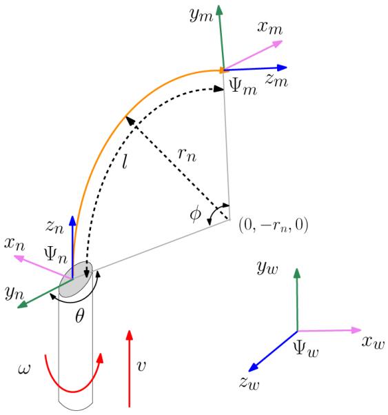
Needle kinematic model in world reference frame ψw. A body coordinate frame ψn is rigidly attached to needle tip. The axes are aligned such that the z-axis is the direction of forward motion, and the bevel tip causes the needle to rotate instantaneously around the line parallel to the x-axis and passing through the point (0, −rn, 0). The needle path (shown in orange) is parameterized as a triplet (l, rn, θ).
The instantaneous linear and angular velocities of the needle are described by a twist Vwn(t) ∈ se(3) [13], which in body coordinates ψn is expressed in matrix notation as:
The twist relates to gwn as: . When the twist is constant, the above equation becomes a linear ordinary differential equation that can be integrated as:
| (2) |
for which a relatively simple analytic expression exists [13]. We refer the reader to [19] for additional details.
In recent work, Minhas et al. [12] relax the constraint of constant-curvature trajectories for the steerable needle by performing duty cycling. By constantly spinning the needle during insertion at a speed much greater than the insertion speed (w(t) ⪢ v(t)), proportional control of the curvature of the needle trajectory through the tissue can be achieved. This results in needle trajectories of bounded-curvature (κ < κn, or equivalently, r > rn). Duty cycling provides even greater mobility for the steerable needle, resulting in faster computation of feasible trajectories and motion plans.
Let the insertion time T be discretized into regular time periods as {Δ, 2Δ, … , T}. In order to incorporate a duty cycle factor of τ (proportion of the duty cycle period Δ spent in constantly rotating the needle during insertion) into the needle kinematic model, the control inputs of the needle (v(t), ω(t)) are adjusted as:
| (3) |
for any and where k is a sufficiently large constant such that the condition ω(t) ⪢ v(t) is satisfied. Minhas et al. [12] experimentally verified that when using duty cycling, the duty cycle factor τ is inversely proportional to the curvature κ and is given by τ = (1 – (κ/κn)).
For the purposes of this work, we construct trajectories for steerable needles that are composed of piece-wise circular arcs {C1, C2, … , CN} (as described in Sec. IV). Each circular arc segment Ci is parameterized as a triplet (li, ri, θi), where li is the arc length, ri is the arc radius, and θi is the change in orientation of the needle tip coordinate frame ψn around the z-axis (as illustrated in Fig. 2). Given a feasible needle trajectory, the motion plan (described as a sequence of discretized control inputs) can be extracted using the concept of duty cycling described above (as outlined in Sec. IV-B).
IV. METHOD
We present a sampling-based motion planning algorithm for computing feasible motion plans for steerable needles in 3D environments with obstacles. Our approach proceeds in two phases. First, we compute a geometric trajectory using an RRT-based planner. Second, we convert the geometric trajectory into a motion plan (needle insertion velocity and twists) based on duty cycling.
A. Computing Feasible Geometric Trajectories
We use an RRT-based motion planning algorithm, augmented with a reachability-guided sampling heuristic proposed by Shkolnik et al. [18], to compute feasible trajectories for the steerable needle. The algorithm is outlined in Alg. 1. Given an initial configuration qinit and a goal region Qgoal, the planner incrementally builds a set of inter-connected configurations that form a tree-like structure over the state space of the steerable needle, while respecting the nonholonomic constraints of the needle motion model and avoiding obstacles in the environment. This process is repeated until either the tree connects the initial configuration and the goal region, or the maximum number of iterations is exceeded, in which case the algorithm reports that a solution cannot be found. A path connecting qinit to qgoal ∈ Qgoal can then be found by traversing the tree from the goal to the root.
Algorithm 1.
| 1: | |
| 2: | while ( and k < K) do |
| 3: | repeat |
| 4: | prand ← RANDOM_POINT_R3() |
| 5: | Qreach = ∅ |
| 6: | for all do |
| 7: | if REACHABLE(prand, qi) then |
| 8: | Qreach ← Qreach ⋃ qi |
| 9: | end if |
| 10: | end for |
| 11: | until Qreach = ∅ |
| 12: | qnear ← NEAREST_NEIGHBOR_R3(prand,Qreach) |
| 13: | |
| 14: | qnew ← NEW_STATE(qnear, u) |
| 15: | if VALID_EDGE(qnear, qnew, u) then |
| 16: | |
| 17: | |
| 18: | end if |
| 19: | k ← k + 1 |
| 20: | end while |
| 21: | return |
In a classic RRT algorithm [11], the tree is expanded iteratively. A random configuration qrand is sampled from the state space χ according to a predefined sampling distribution. The algorithm then identifies the node in the tree qnear, that is closest to the configuration qrand, as defined by a specified distance metric ρ(q). The algorithm then attempts to expand towards qrand based upon the best known control input u that drives the configuration qnear towards qrand and the resulting configuration qnew is added to the tree. For a nonholonomic system like the steerable needle, previous approaches [21], [22] rely on deterministic or uniform random sampling of control inputs to determine the control input u : (v, ω) that results in a new configuration qnew that is closest to qrand, which is a major computational bottleneck.
To avoid having to perform random sampling of control inputs to compute the best control input, we encode segments of a needle trajectory using geometric quantities instead of the actual control inputs (v, ω). Each trajectory is composed of piece-wise circular arcs {C1, C2, … , CN}, where each circular arc Ci is parameterized as a triplet ui : (li, ri, θi) as described in Sec. III. The control inputs are derived later from a given trajectory as explained in Sec. IV-B.
Under the bounded-curvature assumption, we can solve for the exact trajectory parameters u : (l, r, θ) (routine SOLVE_PARAMETERS in Alg. 1) as follows. We adopt a modified sampling strategy in which we sample a random point as opposed to sampling a random configuration from the state space χ (routine RANDOM_POINT_R3 in Alg. 1). For the needle tip configuration specified by configuration q, the reachable set comprising of all points that can be reached by the needle tip is constrained to be inside the volume of a region defined locally by
| (4) |
as shown in Fig. 3. The reachable set of configuration q has to satisfy the above reachability condition (routine REACHABLE in Alg. 1). It should be noted that previous approaches [21], [22] constrained the needle reachable set to be on the surface of the region illustrated in Fig. 3, while the reachable set under the bounded-curvature assumption is the entire volume inside the region.
Fig. 3.
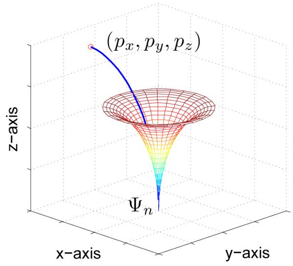
The reachable set for the steerable needle in the local coordinate frame of the needle-tip ψn is constrained to be inside the volume of the region defined locally by Eq. 4 (shown by the colored mesh). Point p = (px, py, pz) can be reached by the needle tip.
Let C : (l, r, θ) be a circular arc connecting the configuration q to point prand lying within the reachable set of q. Expressing the point prand in polar coordinates with respect to the needle tip reference frame ψn gives us the following relations: px = r cos θ(1 – cos ϕ), py = r sin θ(1 – cos ϕ), pz = r sin ϕ, l = rϕ. The exact parameters u: (l, r, θ) associated with the circular arc C can then be extracted as:
| (5) |
The 4 × 4 transformation matrix gi that encodes the final configuration of the needle tip qnew in the local coordinate frame ψn of the configuration q (corresponding to the circular arc Ci) is given by:
The final configuration of the needle tip qnew in the world coordinate frame ψW can be analytically computed as (routine NEW_STATE in Alg. 1) .
Reachability-Guided Sampling Heuristic
The efficiency with which the RRT algorithm is able to grow the tree and explore the state space is highly sensitive to the distance metric ρ(q) used to compute the nearest node in the tree. In the presence of kinematic and dynamic constraints, widely-used metrics like the Euclidean distance are a very poor approximation of the true distance between points in the constrained state space. The performance of the RRT planner degrades as a result of repeated attempts at extending the same nodes in the tree without making sufficient progress. It is also often difficult to specify a good distance metric for complicated nonholonomic systems like the steerable needle. We use the reachability-guided sampling scheme suggested by Shkolnik et al. [18] to alleviate the sensitivity of the RRT planner to the choice of the distance metric through a variation of the nearest-neighbor strategy that restricts the search domain to only those nodes that are within the reachable set of the nearest node qnear, thus increasing the likelihood of expansion of the state space.
As indicated in lines (3 – 11) of Alg. 1, the sampling strategy rejects any random points that do not lie within the reachable set of any node in the tree as determined by the reachability condition given in Eqn. 4. We used the standard Euclidean distance metric in for choosing the nearest configuration qnear from the set of feasible tree nodes Qreach that satisfy the reachability criterion. We also include a small goal bias [11] in our experiments to bias the growth of the tree towards the goal region. From our experiments, we have observed that the reachability-guided sampling and goal-bias heuristic yield dramatic improvements in the performance of the RRT planner.
Collision Checking
An important component of the RRT-based planner is to check if a random configuration qrand or the circular arc connecting the configurations qnear and qnew is valid, i.e. collision-free with respect to obstacles in the environment (routine VALID_EDGE(qnear, qnew, u) in Alg. 1). It is necessary to have an efficient collision checking routine for arbitrary, polyhedral obstacles in order to plan at interactive rates. In practice, the obstacle definitions are obtained from segmentation of 3D scans obtained from imaging devices and it is possible that the triangular surface mesh representing the obstacle may be non-manifold. In this case, any point-in-polyhedron test fails because the mesh is non-manifold or not closed. We use the open-source convex decomposition library distributed with the Bullet Physics library [4] to decompose the mesh into approximate convex pieces and their corresponding Oriented Bounding Boxes (OBB), which can be used for efficient collision detection and distance queries (as shown in Fig. 4).
Fig. 4.
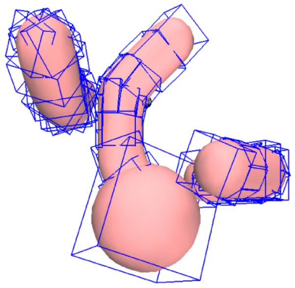
Convex decomposition is used to decompose arbitrary, triangular meshes into approximate convex pieces and their corresponding Oriented Bounding Boxes or OBBs (shown in blue) for efficient collision detection detection and distance queries [4].
B. Computing Motion Plan from Geometric Trajectory
Given the feasible geometric trajectory composed of piece-wise circular arcs {C1, C2, … , CN}, we next compute a motion plan comprising of a sequence of controls (v(t), ω(t)) that specifies needle insertion velocity and twists to reach the target and avoid obstacles.
As described in Sec. III, without loss of generality we assume v(t) = vfixed ≡ 1. This is equivalent to parameterizing the trajectory by insertion distance instead of time. One side-effect is that we have to allow for impulsive ω(t) when changing the needle tip orientation when v = 0, but this does not pose any limitations. The duration of needle insertion Ti corresponding to the segment Ci is given by Ti = li/vfixed ≡ li. Let Ti be discretized into regular time periods Δ as {Δ, 2Δ, … , Ti}. The control inputs corresponding to segment Ci are then given by:
| (6) |
for any and where k is a sufficiently large constant such that the condition ω(t) ⪢ v(t) is satisfied. The first term ω(t) = θ at t = 0 corresponds to the correction of the needle orientation at the beginning of segment Ci. The second and third relationships correspond to using duty cycling for the duration Ti (as given in Eqn. 3). Given the control inputs, the needle trajectory can be computed as outlined in Sec. III-B.
V. Results
We implemented the motion planner in C++ and tested it on a 3.33 Ghz 4-core Intel® i7™ PC. The radius of curvature of the steerable needle inside tissue is assumed to be 0.05 m, which is approximately the radius of curvature achieved for steerable needles in recent experiments [9], [16].
We consider three test environments as shown in Figs. 5, 6, and 7. For each test case, we model the environment to be a cubical region measuring 0.2 m along each axis. We model the goal target zone Qgoal as a spherical region with a radius of 0.002 m. We set the maximum number of iterations for the RRT planner to 5000 and the goal bias factor to 0.25. To optimize the motion plan, we execute the RRT planner for 100 different initial configurations, each chosen using a uniform random distribution in the entry region, which is modeled as a rectangular region centered at (0.1 m, 0.1 m, 0.0 m), and select the motion plan that minimizes the optimization criterion. For fast performance, the RRT planner executions are run in parallel across the available processing cores using OpenMP.
Fig. 5.
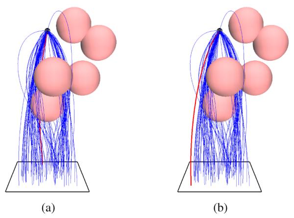
Test Case 1: Spherical Obstacles. The rectangular entry region is shown as a black rectangle at the base of the environment. (a) Optimal needle trajectory that minimizes the needle insertion depth (αl = 1, αo = 0). (b) Optimal needle trajectory that maximizes the clearance from the obstacles (αl = 0, αo = 1).
Fig. 6.
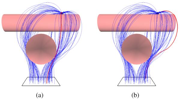
Test Case 2: Cylindrical Obstacles. The size and close proximity of the cylindrical obstacles introduces narrow passages in the steerable needle’s configuration space. (a) Optimal needle trajectory (shown in red) that minimizes the needle insertion depth (αl = 1, αo = 0). (b) Optimal needle trajectory that maximizes the clearance from the obstacles (αl = 0, αo = 1).
Fig. 7.
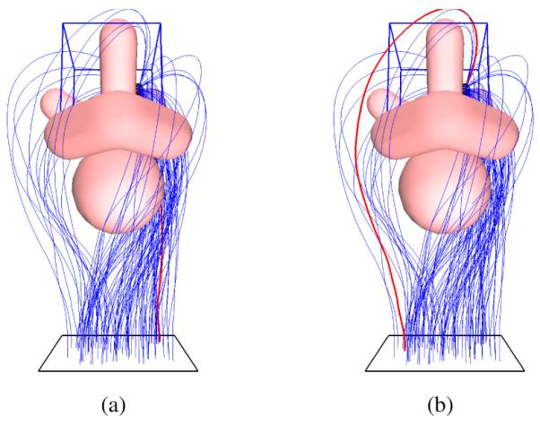
Test Case 3: Prostate Anatomy. To simulate the environment encountered by physicians performing prostate brachytherapy cancer treatment, we use a model of anatomical obstacles including the urethra, penile bulb, pubic bone, and seminal vesicles around the prostate (labeled in Fig. 1) as in Xu et al. [22]. (a) Optimal needle trajectory (shown in red) that minimizes needle insertion depth (αl = 1, αo = 0). (b) Optimal needle trajectory that maximizes the clearance from the obstacles (αl = 0, αo = 1).
Test Case 1: Spherical Obstacles
We define an environment consisting of six spherical obstacles, each of radii 0.02 m, based on the test case defined in Xu et al. [21]. Fig. 5 shows the needle motion plans computed by our planner. For this test case, Xu et al. [21] report that their RRT motion planner has a success rate of 50% and takes an average of 1851 seconds to compute a feasible motion plan on an Intel Centrino® 1.66 Ghz processor while our approach has a 100% success rate and takes an average of 0.002 seconds to compute a single feasible plan on a single core of an Intel® i7 3.33 Ghz processor.
Test Case 2: Cylindrical Obstacles
We define an environment consisting of two orthogonal cylinders as used for demonstration by Chentanez et al. [5]. The target is positioned such that the needle must be maneuvered around both obstacles. The size and close proximity of the cylindrical obstacles introduces narrow passages in the steerable needle’s state space. Fig. 6 shows the needle motion plans computed by the planner. In this case, the weights (αl, αo) of the optimization criterion (Eqn. 1) can be interactively tuned to achieve a desired trade-off between choosing a shortest path that runs very close to obstacles and a path of maximal clearance that is unnecessarily circuitous.
Test Case 3: Prostate Anatomy
To simulate the environment encountered by physicians performing prostate brachytherapy cancer treatment, we use a model of anatomical obstacles including the urethra, penile bulb, pubic bone, and seminal vesicles around the prostate as in Xu et al. [22]. The obstacles are defined using triangular meshes. Fig. 7 shows the needle trajectories computed by the planner. When minimizing insertion depth, the planner routes the needle through the narrow passage between the pubic bone and the penile bulb. This narrow passage is avoided when the optimization criterion is changed to maximize the clearance to the obstacles.
Method Performance
Table I summarizes the performance of our system on the three test cases. The third column reports the percentage of successful runs among multiple runs starting from 100 different initial configurations. The fifth column reports the CPU times (mean ± standard deviation) needed to compute a single feasible plan. The sixth column reports the total CPU time (incorporating parallelization) taken to compute an optimal motion plan chosen from among all trial runs. The results indicate that our method can be used to interactively compute hundreds of feasible motion plans for steerable needles in under a second even in challenging 3D environments with polyhedral obstacles and narrow passages.
TABLE I.
Performance of our approach on the three test cases.
| Test Case |
#Trials | % Successful runs |
Avg. no. iterations |
Avg. CPU time (secs) |
Total CPU time (secs) |
|---|---|---|---|---|---|
| 1 | 100 | 100 | 165 (± 118) | 0.0021 (± 0.0017) | 0.026 |
| 2 | 100 | 100 | 1202 (± 838) | 0.0386 (± 0.0463) | 0.483 |
| 3 | 100 | 100 | 435 (± 239) | 0.0438 (± 0.0295) | 0.548 |
VI. Conclusions and Future Work
In this paper, we presented a fast algorithm that can compute motion plans for steerable needles to reach targets in complex, 3D environments with obstacles at interactive rates. Prior methods for this problem require multiple seconds or minutes to compute a single motion plan [7], [21], [22]; our motion planner offers an orders of magnitude speed-up compared to prior work by computing hundreds of feasible motion plans in less than a second.
The fast computation makes this method suitable for online control of the steerable needle based on 3D imaging feedback and allows physicians to interactively edit the planning environment in real-time by adding obstacle definitions as they are discovered or become relevant. We achieve this fast performance by using a Rapidly Exploring Random Tree (RRT) combined with a reachability-guided sampling heuristic to alleviate the sensitivity of the RRT planner to the choice of the distance metric. We also relax the constraint of constant-curvature needle trajectories by relying on duty cycling to realize bounded-curvature needle trajectories. The fast performance also provides a family of solutions, enabling the clinician to select a high quality plan based on an optimization criterion.
In future work, we plan to integrate our planner with a real-time feedback controller operating under sensing feedback and carry out experiments on tissue phantoms. We will utilize the ability of this planner to compute motion plans at interactive rates in order to rapidly re-plan when unexpected events occur due to tissue inhomogeneity, tissue deformation, and estimation errors in motion model parameters.
VII. Acknowledgements
This research was supported in part by the National Science Foundation (NSF) under grant #IIS-0905344 and by the National Institutes of Health (NIH) under grant # R21EB011628. The authors also thank R. J. Webster III, J. Xu, K. Goldberg, and others in the needle steering community for their valuable input.
References
- [1].Alterovitz R, Branicky M, Goldberg K. Motion planning under uncertainty for image-guided medical needle steering. Int. J. Robotics Research. 2008 Nov.vol. 27(no. 11–12):1361–1374. doi: 10.1177/0278364908097661. [DOI] [PMC free article] [PubMed] [Google Scholar]
- [2].Alterovitz R, Goldberg K, Okamura AM. Planning for steerable bevel-tip needle insertion through 2D soft tissue with obstacles. Proc. IEEE Int. Conf. Robotics and Automation (ICRA); Apr. 2005.pp. 1652–1657. [Google Scholar]
- [3].Alterovitz R, Siméon T, Goldberg K. The Stochastic Motion Roadmap: A sampling framework for planning with Markov motion uncertainty. In: Burgard W, Brock O, Stachniss C, editors. Robotics: Science and Systems III (Proc. RSS 2007) MIT Press; Cambridge, MA: 2008. pp. 246–253. [Google Scholar]
- [4].BulletPhysics. 2010 http://www.bulletphysics.com/
- [5].Chentanez N, Alterovitz R, Ritchie D, Cho J, Hauser K, Goldberg K, Shewchuk JR, O’Brien JF. Interactive simulation of surgical needle insertion and steering. ACM Transactions on Graphics (Proc. SIGGRAPH) 2009 Aug.vol. 28(no. 3):88:1–88:10. [Google Scholar]
- [6].DiMaio SP, Salcudean SE. Needle steering and motion planning in soft tissues. IEEE Trans. Biomedical Engineering. 2005 June;vol. 52(no. 6):965–974. doi: 10.1109/TBME.2005.846734. [DOI] [PubMed] [Google Scholar]
- [7].Duindam V, Alterovitz R, Sastry S, Goldberg K. Screw-based motion planning for bevel-tip flexible needles in 3D environments with obstacles. Proc. of IEEE Int. Conf. on Robotics and Automation; 2008. pp. 2483–2488. [DOI] [PMC free article] [PubMed] [Google Scholar]
- [8].Duindam V, Xu J, Alterovitz R, Sastry S, Goldberg K. 3D motion planning algorithms for steerable needles using inverse kinematics. Eighth Int. Workshop on Algorithmic Foundations of Robotics (WAFR); 2008. [DOI] [PMC free article] [PubMed] [Google Scholar]
- [9].Engh JA, Podnar G, Kondziolka D, Riviere CN. Toward effective needle steering in brain tissue. Proc. Int. Conf. IEEE Engg. In Medicine and Biology Society; Sept. 2006; pp. 559–562. [DOI] [PubMed] [Google Scholar]
- [10].Hauser K, Alterovitz R, Chentanez N, Okamura A, Goldberg K. Feedback control for steering needles through 3D deformable tissue using helical paths. Proc. of Robotics: Science and Systems; 2009. [DOI] [PMC free article] [PubMed] [Google Scholar]
- [11].Kuffner JJ, LaValle SM. RRT-connect: An efficient approach to single-query path planning. Proc. IEEE Int. Conf. on Robotics and Automation.2000. pp. 995–1001. [Google Scholar]
- [12].Minhas D, Engh JA, Fenske MM, Riviere C. Modeling of needle steering via duty-cycled spinning. Proc. Int. Conf. IEEE Eng. in Medicine and Biology Society; 2007. pp. 2756–2759. [DOI] [PubMed] [Google Scholar]
- [13].Murray R, Li ZX, Sastry S. A Mathematical Introduction to Robotic Manipulation. CRC Press; 1994. [Google Scholar]
- [14].Okazawa S, Ebrahimi R, Chuang J, Salcudean SE, Rohling R. Hand-held steerable needle device. IEEE/ASME Trans. Mechatronics. 2005 June;vol. 10(no. 3):285–296. [Google Scholar]
- [15].Park W, Kim JS, Zhou Y, Cowan NJ, Okamura AM, Chirikjian GS. Diffusion based motion planning for a nonholonomic flexible needle model. Proc. of IEEE Int. Conf. on Robotics and Automation.2005. pp. 4611–4616. [Google Scholar]
- [16].Reed KB, Kallem V, Alterovitz R, Goldberg K, Okamura AM, Cowan NJ. Integrated planning and image-guided control for planar needle-steering. Proc. IEEE/RAS-EMBS Int. Conf. on Biomedical Robotics and Biomechatronics; 2008. pp. 819–824. [DOI] [PMC free article] [PubMed] [Google Scholar]
- [17].Sears P, Dupont P. A steerable needle technology using curved concentric tubes. Proc. IEEE/RSJ Int. Conf. on Intelligent Robots and Systems (IROS); Oct. 2006.pp. 2850–2856. [Google Scholar]
- [18].Shkolnik A, Walter M, Tedrake R. Reachability-guided sampling for planning under differential constraints. Proc. IEEE Int. Conf. on Robotics and Automation.2009. pp. 4387–4393. [Google Scholar]
- [19].Webster RJ, III, Kim JS, Cowan NJ, Chirikjian GS, Okamura AM. Nonholonomic modeling of needle steering. Int. J. Robotics Research. 2006 May;vol. 25(no. 5–6):509–525. [Google Scholar]
- [20].Webster RJ, III, Okamura AM, Cowan NJ. Toward active cannulas: Miniature snake-like surgical robots. Proc. IEEE/RSJ Int. Conf. on Intelligent Robots and Systems (IROS).2006. pp. 2857–2863. [Google Scholar]
- [21].Xu J, Duindam V, Alterovitz R, Goldberg K. Motion planning for steerable needles in 3d environments with obstacles using rapidly-exploring random trees and backchaining. Proc. IEEE Int. Conf. Automation Science and Engineering (CASE); Aug. 2008.pp. 41–46. [Google Scholar]
- [22].Xu J, Duindam V, Alterovitz R, Pouliot J, Cunha JAM, Hsu I-C, Goldberg K. Planning fireworks trajectories for steerable medical needles to reduce patient trauma. Proc. IEEE/RSJ Int. Conf. on Intelligent Robots and Systems (IROS); Oct. 2009; pp. 4517–4522. [DOI] [PMC free article] [PubMed] [Google Scholar]


