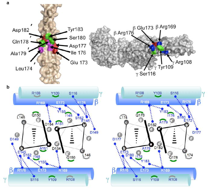
Figure 2. M1-Fg interface.

a, Interface between M1BC1 B2 (left, primed numbers refer to one helix and non-primed the opposing helix) and FgD (right) in surface representation (basic residues blue, acidic red, polar green, and nonpolar magenta). b, Schematic of the interface between M1BC1 B1 (left) and B2 (right) in helical projection and FgD (cylinders, β chain in blue and γ in blue-green). Blue dotted lines connect residues making polar contacts, and gray and green arcs correspond to M1 residues making van der Waals contacts to Fg γ 108 and 109, respectively.
