Abstract
Here we describe a method for the engineered regulation of protein kinases in living cells, the design and application of RapR (rapamycin regulated) kinases. The RapR kinase method enables activation of kinases with high specificity and precise temporal control. Insertion of an engineered allosteric switch, the iFKBP domain, at a structurally conserved position within the kinase catalytic domain makes the modified kinase inactive. Treatment with rapamycin or its non-immunosuppresive analogs triggers interaction with a small FKBP-rapamycin-binding domain (FRB), restoring the activity of the kinase. The reagents used in this method are genetically encoded or membrane permeable, enabling ready application in many systems. Based on the structural similarity of kinase catalytic domains, this method is likely applicable to a wide variety of kinases. Successful regulation has already been demonstrated for three kinases representing both tyrosine and serine/threonine kinase families (p38, FAK, Src). Procedures for designing and testing RapR kinases are discussed.
Keywords: kinase, allosteric, activation, phosphorylation
INTRODUCTION
Protein kinases comprise nearly 2% of the human genome (Manning et al., 2002). Phosphorylation of proteins by kinases is a key regulatory step in virtually all essential processes in mammalian cells. A substantial number of kinases are implicated in the development and progression of human diseases. Hence, kinases are the subject of extensive biological studies and in many cases are targets for therapeutic treatment. Manipulation of the catalytic activity of kinases provides an important opportunity to understand the role of these key players in a broad range of important signaling pathways.
The most common methods for manipulation of kinase activity include overexpression of mutants, pharmacological inhibitors, and downregulation of kinase expression by siRNA or genetic modifications. Downregulation and overexpression of kinases enable targeted control, but do not provide temporal control. Application of pharmacological inhibitors allows excellent temporal control but is often not sufficiently specific. An elegant method developed by Shokat overcomes the problem of kinase inhibitor specificity by utilizing mutant kinases that can be specifically targeted by modified analogs of the existing inhibitors (Bishop et al., 2001). In contrast to these methods, the RapR approach combines specificity, temporal control, and activation rather than inhibition.
Several approaches have been used for activation of kinases in living cells, but their applications are limited to specific cases. For certain receptor tyrosine kinases, activation has been achieved by drug-induced dimerization of the kinase (Spencer et al., 1993). Alternately, the activity of a specifically designed kinase mutant can be rescued by treatment with imidazole or its analogs (Qiao et al., 2006). The method provides very specific and reversible activation, but its design is limited to the tyrosine kinase family and requires treatment with high concentration (5mM) imidazole. The RapR method enables specific activation of a broad variety of kinases with temporal control in living cells.
We make use of the well characterized rapamycin-mediated heterodimerization of small FK506-binding protein (FKBP12) and an FKBP12-rapamycin-binding (FRB) domain of mTOR. The advantages of this system include tight and quick regulation of complex formation, use of genetically encoded and membrane permeable reagents, the small size of FKBP12 and FRB tags (90–120 amino acids), and the availability of non-immunosupressive analogs of rapamycin. A growing number of studies have demonstrated successful application of this dimerization approach for experiments in live cells and in animal models (Inoue et al., 2005; Rivera et al., 1999; Spencer et al., 1993; Stankunas et al., 2003).
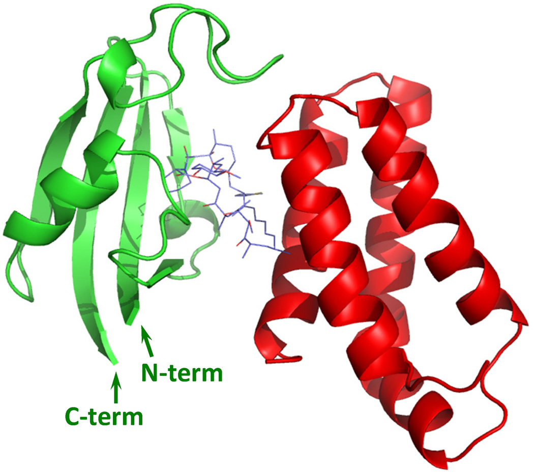
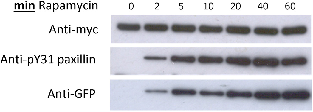
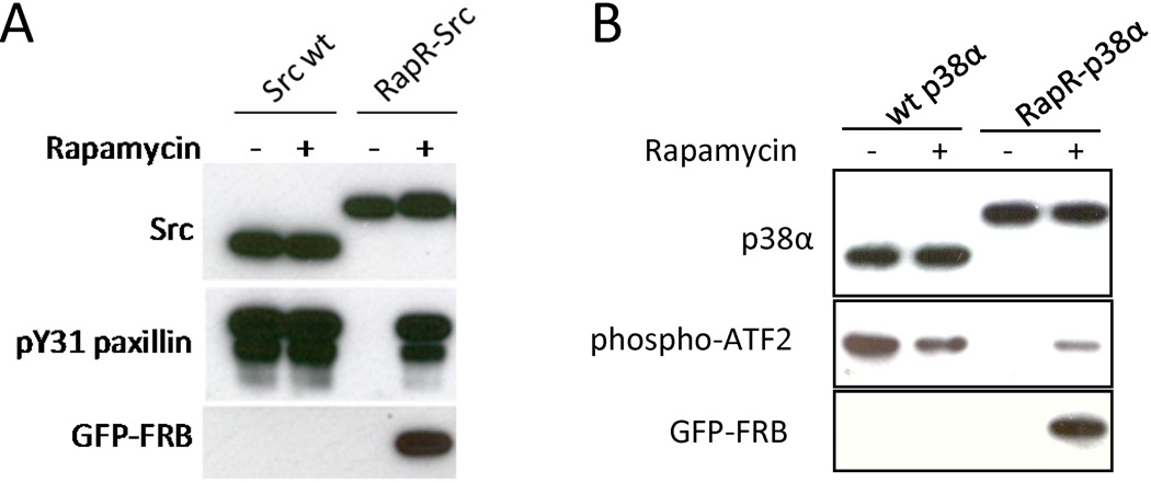
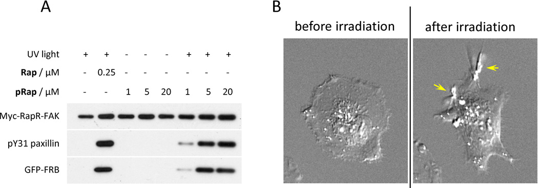
To achieve regulation of kinases, we created a modified FKBP12 protein suitable for insertion into the middle of other proteins (insertable FKBP, or iFKBP) (Fig. 1), and used it as an allosteric switch to regulate the catalytic activity of focal adhesion kinase (FAK) (Karginov et al., 2010a). Insertion of iFKBP into a structurally conserved portion of the kinase catalytic domain rendered FAK inactive. Importantly, this modification did not affect FAK’s localization or its interaction with binding partners. The catalytic activity of FAK was rapidly restored upon interaction with rapamycin and co-expressed FRB protein (Fig. 2). Molecular modeling and structure-activity studies indicated that the rigidity of a critical G-loop in the catalytic domain is decreased due to the high dynamic mobility of the inserted iFKBP domain, disrupting kinase activity. Binding to rapamycin and FRB significantly reduced the mobility of iFKBP, restoring the stability of the G-loop and catalytic activity of the kinase (Fig. 3). Using this new tool, we demonstrated that FAK directly activates Src in live cells, stimulating formation of large dorsal protrusions, a novel finding that suggested a new mechanism for FAK involvement in tumorigenesis. We have shown that RapR FAK can also be regulated by non-immunosupressive analogs of rapamycin (iRap and AP21967), demonstrating its potential for experiments in animals. The site of iFKBP insertion is structurally conserved among all kinases, suggesting that the new approach can be broadly applied. This was supported by the successful development of rapamycin-regulatable variants of the tyrosine kinase Src, and a serine/threonine kinase p38α (Fig. 4). In collaboration with Dr. A. Deiters at North Carolina State University we have recently developed a “caged” rapamycin molecule, in which an o-nitrobenzyl photocleavable protecting group inactivates the molecule until it is irradiated (Karginov et al., 2010b). The caged rapamycin had no effect on RapR-FAK until treatment with 360nm light, which generated FAK-mediated dorsal ruffles (Fig. 5) (Karginov et al., 2010b). Here we describe methodology for design and development of RapR-kinases using FAK as an example.
Fig. 1.
Predicted stricture of iFKBP (green) in complex with the FRB domain (red) and rapamycin. The N- and C-termini of iFKBP are positioned next to each other, allowing for insertion of iFKBP into small loops within protein structures. The model is based on crystal structure of FKBP12-rapamycin-FRB complex (PDB ID: 4FAP).
Fig. 2.
Rapamycin-mediated regulation of modified FAK (RapR-FAK). HEK293T cells co-expressing myc-tagged RapR-FAK and GFP-FRB were treated with 200 nM rapamycin for the indicated period of time. The kinase was immunoprecipitated and its activity was tested using the N-terminal fragment of paxillin as a substrate. Phosphorylation level of paxillin on Tyr31 indicates the activity of FAK. Reprinted with permission from {Karginov AV, Ding F, Kota P, Dokholyan NV, Hahn KM (2010) Nat Biotechnol;28(7):743-7}.
Fig. 3.
Mechanism of regulation by iFKBP. Tube representation depicting changes in the dynamics of the FAK catalytic domain. Warmer colors and thicker backbone indicate greater free movement within the structure. The red arrows points to the G-loop, critical for catalytic activity. iFKBP was placed in the insertion loop of FAK wt to generate RapR-FAK. The mobility of the iFKBP was transmitted to the G loop, rendering it sensitive to rapamycin/FRB binding. Reprinted with permission from {Karginov AV, Ding F, Kota P, Dokholyan NV, Hahn KM (2010) Nat Biotechnol;28(7):743-7}.
Fig. 4.
Regulation of different RapR-kinases. (A) HEK293T cells co-expressing myc-tagged Src and GFP-FRB constructs were treated for one hour with either 200 nM rapamycin or ethanol (solvent control). The activity of immunoprecipitated Src was tested using the N-terminal fragment of paxillin as a substrate. (B) Regulation of p38α kinase by insertion of iFKBP. HEK293T cells co-expressing the indicated flag-tagged p38α construct and GFP-FRB were treated with either 200 nM rapamycin or ethanol solvent control. The kinase activity of p38α was tested in vitro using ATF2 as a substrate. Reprinted with permission from {Karginov AV, Ding F, Kota P, Dokholyan NV, Hahn KM (2010) Nat Biotechnol;28(7):743-7}.
Fig. 5.
Light-mediated activation of a protein kinase. (A) Myc-RapR-FAK kinase was co-expressed with GFP-FRB in HEK293T cells. Cells were treated with the indicated amount of rapamycin (Rap), caged rapamycin (pRap), or DMSO (control). The indicated samples were exposed to UV light (365 nm, 1 min). All cells were incubated at 37 °C for 1 hour after treatment. Myc-RapR-FAK was immunoprecipitated using an anti-myc antibody and tested in a kinase assay using an N-terminal fragment of paxillin as a substrate. The level of phosphorylation of paxillin on Tyr31 indicates kinase activity. (B) HeLa cells co-transfected with GFP-RapR-FAK and Cherry-FRB were treated with pRap (1 µM) and imaged before and after UV irradiation (365 nm, 1 min). Arrows indicate formation of large dorsal ruffles stimulated by activated RapR-FAK. Reprinted with permission from {Karginov AV, Zou Y, Shirvanyants D, Kota P, Dokholyan NV, Young DD, Hahn KM, Deiters A (2011) J Am Chem Soc, 133 (3), pp 420–423, DOI: 10.1021/ja109630v}. Copyright {2010} American Chemical Society.
STRATEGIC PLANNING
One of the key requirements for the development of a RapR kinase is the availability of a reliable method to test the activity of the targeted kinase. The method we used for FAK requires in vitro assessment of kinase activity after immunoprecipitation from cell extract. Each kinase assay must be optimized on a case by case basis. The conditions described here were optimized for FAK.
The assays we used were based on immunoprecipitation using myc and flag tags. These were placed at the N-terminus of FAK and p38. However, due to lipid modification of Src at the N-terminus it had to be tagged at the C-terminus. A tag is not necessary as long as the kinase can be immunoprecipitated using a kinase-specific antibody and its activity can be tested in vitro. With untagged kinases, immunoprecipitation of endogenous kinases may elevate background levels of kinase activity in the assay.
We have chosen to apply the RapR approach to constitutively active kinases. This insures that kinase activity is strictly under the control of the experimentalist, and not subject to regulation by endogenous signaling pathways. In some studies it may be valuable to activate wild type, regulated kinase.
For the actual design of the RapR kinase, it is very helpful to have a crystal structure of the targeted kinase’s catalytic domain. A crystal structure can guide identification of the position for insertion of iFKBP. If necessary, the crystal structure of a close homolog can suffice, or the position for insertion of iFKBP can be even deduced through comparison of the targeted kinase sequence to sequences of non-related kinases.
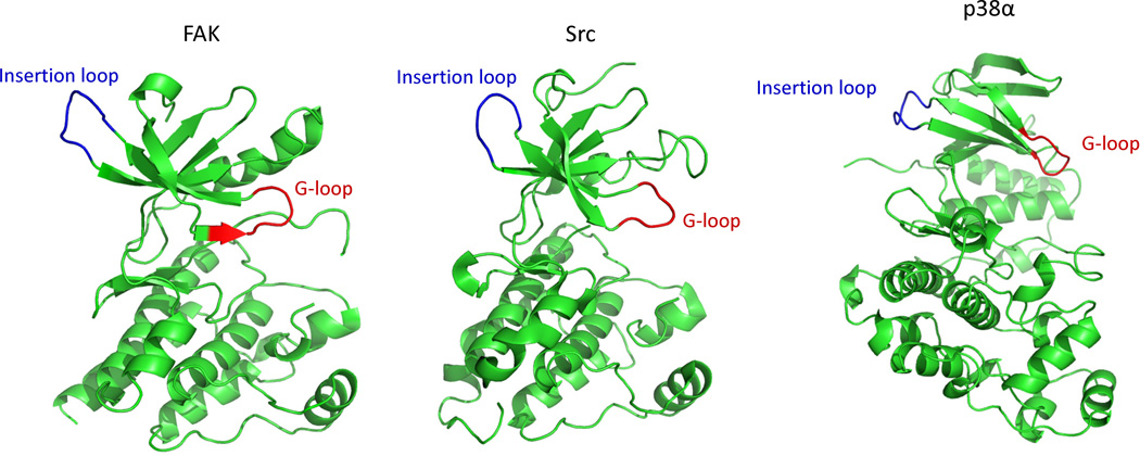
Selection of the insertion site for iFKBP is based on the fact that the catalytic domain structure for all members of the eukaryotic protein kinase (ePK) superfamily is very similar. As depicted in Fig. 6, the iFKBP is positioned in the conserved structure we call the “insertion loop”. This is in the β-sheet structured N-terminal lobe of the catalytic domain, a loop opposite the G-loop described in published studies as a critical structural element of all ePKs (Krupa et al., 2004). If a structure of the targeted catalytic domain is unavailable, one can identify the insertion loop by comparing its amino acid sequence to a protein kinase with known structure. Due to the high degree of conservation this can be accomplished even by comparison with unrelated kinases. By comparing the amino acid sequences of the tyrosine kinase Src and the serine/threonine kinase p38 we could readily identify the site for insertion of iFKBP (Fig. 7). Our experiments demonstrated that insertion of iFKBP at the selected site led to successful generation of both RapR-Src and RapR-p38 (Fig. 4).
Fig. 6.
Position of the insertion loop in the catalytic domain of different kinases: FAK (PDB ID: 2J0M), Src (PDB ID: 1YOJ) and p38 (PDB ID: 1p38). Reprinted with permission from {Karginov AV, Ding F, Kota P, Dokholyan NV, Hahn KM (2010) Nat Biotechnol;28(7):743-7}.
Fig. 7.
Amino acid sequence comparison of Src and p38 catalytic domains. The insertion site for iFKBP in RapR-Src and RapR-p38 is indicated by the red arrow and outlined by the red rectangle.
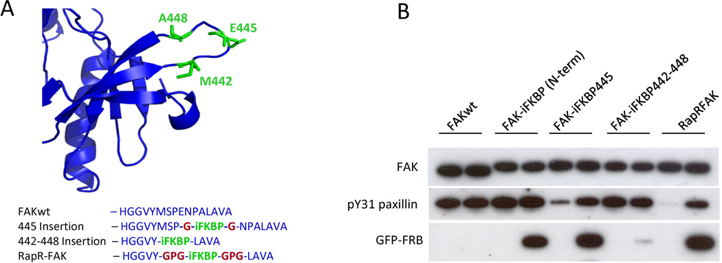
Once the insertion loop is identified, several alternative construct designs can be considered for insertion of iFKBP into the loop: The iFKBP can replace either one amino acid in the loop, or the entire insertion loop (Fig. 8). For FAK, replacing one amino acid in the middle of the loop was not sufficient for tight regulation (Fig 8). Replacement of the entire insertion loop (Met442-Ala448) with iFKBP created the optimal constructs (Fig. 8B). Our studies indicate that replacing the insertion loop with iFKBP using no linkers eliminates the ability of iFKBP to regulate the catalytic domain, and to bind rapamycin and FRB (Fig. 8). We have had success with two linkers that were tested when generating RapR-FAK: a short Gly linker and a longer Gly-Pro-Gly. The short linker may work better for iFKBP insertion replacing only one amino acid in the loop, whereas the longer linker is likely to prove optimal for replacement of the entire insertion loop with iFKBP.
Fig. 8.
Variation of insertion position and linkers for iFKBP insertion into FAK. (A) Sites of iFKBP insertion (green) and connecting linkers (red). (B) Rapamycin regulation of FAK variants with iFKBP inserted at different positions. HEK293T cells co-expressing myc-tagged FAK constructs and GFP-FRB were treated for one hour with either 200 nMrapamycin or ethanol (solvent control). The activity of immunoprecipitated FAK variants was tested using the N-terminal fragment of paxillin as a substrate. Reprinted with permission from {Karginov AV, Ding F, Kota P, Dokholyan NV, Hahn KM (2010) Nat Biotechnol;28(7):743-7}.
As a general rule, if a single amino acid replacement is chosen we recommend replacing the amino acid in the middle of the insertion loop. Ideally the replaced amino acid should be either polar or small (i.e. Glu, Arg, Lys, Gly). Unlike hydrophobic amino acids, such amino acids are more likely to be exposed to solvent.
Another key criterion for iFKBP insertion is involvement of the insertion loop in any known interactions. Insertion of iFKBP into an existing binding site for another protein will likely affect regulation of some of the pathways mediated by the kinase. In the case of FAK, Src and p38 no known interactions involve the insertion loop.
It is important to generate kinase inactive control constructs to test RapR kinase specificity and kinase control in vitro and in vivo. The most common inactivating mutation is replacement of a critical Lys residue in the N-terminal lobe of all catalytic kinases (Lys454 in mouse FAK). However, this residue is in the β-strand directly connected to the iFKBP insertion. Since both the mutation of the Lys and the insertion of iFKBP are potentially destabilizing, introducing both in such close proximity may substantially affect the catalytic domain structure. Thus, we recommend using a different inactivating mutation. A critical Asp residue in the C-terminal lobe of the catalytic domain (catalytic base) is present in all ePKs (Asp546 in mouse FAK) and is essential for the phosphate transfer reaction (Krupa et al., 2004). Mutation of this residue to Arg will efficiently abrogate catalytic activity, and will be sufficiently distanced from the iFKBP insertion site. We used this particular mutation in RapR-FAK and RapR-Src to create “kinase dead” controls (Karginov et al., 2010a).
Multiple alternatives strategies to clone iFKBP into the kinase can be conceived. Here we present a method that has been used successfully to generate all our RapR-kinases. This strategy is based on a known site-directed mutagenesis approach. Unlike more traditional strategies, this method does not require any unique restriction sites for cutting at the site of insertion or for subsequent ligation of DNA fragments. Therefore, this method has no specific sequence requirements for the insertion site and enables creation of any linkers between the catalytic domain and FKBP in one cloning step.
BASIC PROTOCOL 1
GENERATION OF KINASE CONSTRUCTS WITH iFKBP INSERTION
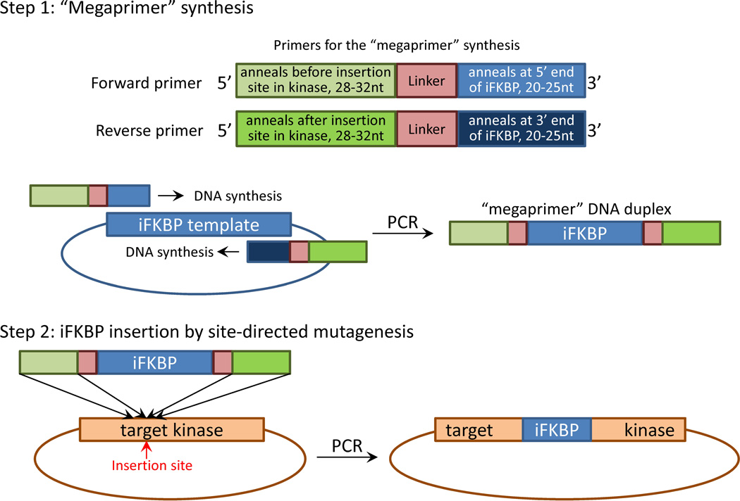
The cloning method described here is based on the same principle as the QuikChange site-directed mutagenesis kit provided by Agilent Technologies, Inc. Although reagents from different sources can be used for this procedure, here we describe a basic protocol using reagents provided by Agilent. The strategy involves two steps (Fig. 9):
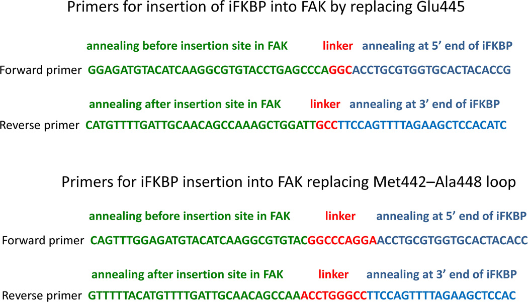
Generation of a “megaprimer” for insertion of iFKBP. Generation of a “megaprimer” encoding the iFKBP insert is accomplished by PCR and requires a specific set of primers. The primers for the “megaprimer” synthesis contain three critical parts (Fig. 9). They should contain a 20–25 nucleotide portion that will anneal at either 5’ or 3’ ends of iFKBP. This is required for synthesis of iFKBP DNA by PCR. Immediately adjacent should be fragments encoding linkers that will connect iFKBP to the catalytic domain of the kinase. Finally, the primers should be flanked by 28–32 nucleotide regions that will anneal either before or after the insertion site in the kinase gene (Fig. 9). As described above, the iFKBP insertion site in the catalytic domain of a kinase can be identified either by kinase structure analysis or by comparison with other kinases with known structure. Here we provide two examples of primers used for insertion of iFKBP into the FAK catalytic domain, using two different linkers and representing the two alternative insertion options (replacing one amino acid or replacing the entire insertion loop; see above) (Fig. 10). The resulting synthesized “megaprimer” DNA duplex will contain the iFKBP insert flanked by the linker sequences and the long kinase annealing sites required for site-directed insertion (Fig. 9).
Insertion of iFKBP by site directed mutagenesis PCR. In the next step, perform PCR using the generated “megaprimer” DNA duplex and the template vector bearing the gene of the targeted kinase, to synthesize a modified DNA construct with iFKBP insertion (Fig. 9). The template plasmid can be efficiently removed by subsequent digestion with DpnI enzyme that selectively digests only methylated DNA. This will significantly increase the yield of the modified construct. Identification of the clones with iFKBP insertion can be accomplished through PCR colony screening using a set of primers that will anneal in the template DNA construct and in the insert (Sandhu et al., 1989). Such a combination of primers will generate product only from colonies that contain constructs with an iFKBP insert.
Below we describe a procedure for generation of two different variants of FAK with iFKBP insertion. This strategy can be easily adapted for insertion of iFKBP into any other kinase.
Fig. 9.
Schematic diagram of cloning strategy for iFKBP insertion into a target kinase. In Step 1, specifically designed primers are used for PCR synthesis of an iFKBP fragment flanked by sites annealing in the target kinase gene before and after insertion site. The iFKBP fragment thus produced is used as a “megaprimer” for insertion of iFKBP into the target kinase gene by site-directed mutagenesis.
Fig. 10.
Primer design for insertion of iFKBP into the FAK catalytic domain.
Materials
pmyc-FAK expression plasmid (developed in Dr. Steven Hanks laboratory)
pmyc-iFKBP-FAK expression plasmid (Addgene)
DNA primers for iFKBP “megaprimer” synthesis (Fig. 10)
PfuTurbo DNA polymerase and 10× reaction buffer (Agilent Technologies)
dNTP mix, 10mM
DpnI restriction endonuclease (different providers, e.g. Agilent Technologies)
LB media and agar plates (APPENDIX 2A)
Transformation-competent DH5α bacterial cells or equivalent (different providers)
DNA primers for colony PCR screen (Fig. 11)
Fig. 11.
Primer design for PCR colony screening.
Taq polymerase reaction kit (Apex™ 2.0× Taq RED Master Mix Kit or equivalent)
DNA gel purification kit (QIAGEN or other providers)
Day 1: Generation of “megaprimer” encoding iFKBP insert
-
1
For each insert conduct a PCR reaction using DNA primers for iFKBP “megaprimer” synthesis and pmyc-iFKBP-FAK construct as a template. For PfuTurbo DNA polymerase use reagents and reaction conditions recommended by Agilent Technologies. Other high-fidelity DNA polymerases suitable for PCR reaction can also be used. Follow the manufacturer’s guidelines for the reaction. The resulting PCR product should be analyzed and purified by DNA gel electrophoresis using either previously described procedures or commercial kits (e.g. QIAGEN DNA gel purification kit). The size of the PCR product should be approximately 400 base pairs. The purified “megaprimer” DNA fragment should be dissolved in water.
Day 1: Insertion of iFKBP into the FAK gene
-
2Using pmyc-FAK expression plasmid as a template and the “megaprimer” perform the following site-directed mutagenesis PCR. For each insert mix in a PCR tube following components:
PfuTurbo DNA polymerase 2.5 Units Purified iFKBP insertion “megaprimer” 200–400 ng Myc-FAK plasmid template 20 ng 10× PfuTurbo reaction buffer (Agilent Technologies) 2.5 µl dNTP, 10 mM 1 µl water add to 25 µl After completion of the PCR reaction add 1 µl of DpnI enzyme and incubate the mixture at 37°C for 1–1.5 hours. Transform 1–2 µl of the PCR reaction into DH5α competent cells following manufacturer protocols or other suitable conditions. Plate transformed bacteria on LB-agar plate with appropriate antibiotic for selection (50 µg/ml of carbenicillin for pmyc-FAK expression construct). Incubate plate at 37°C overnight.
Day 2: Insertion of iFKBP into the FAK gene
-
3
Perform a PCR screen of obtained colonies as described previously (Sandhu et al., 1989). Use a set of primers that will anneal in the template vector and in the insert (Fig. 11). The screen can be performed using Apex™ 2.0× Taq RED Master Mix Kit or equivalent reagents. Once positive clones are identified, inoculate one positive colony into 50 ml LB media (with 50 µg/ml carbenicillin for the pmyc-FAK based constructs) and incubate at 37°C overnight.
Day 3: Insertion of iFKBP into the FAK gene
-
4
Prepare plasmid DNA from the 50ml overnight culture and confirm the iFKBP insertion and the complete modified FAK gene through DNA sequencing.
BASIC PROTOCOL 2
ANALYSIS OF RapR-KINASE ACTIVITY
Different reaction conditions and specific substrates must be used to assay each kinase. Here we describe procedure for biochemical analysis of RapR-FAK activity. Several important controls should be included in this assay: A myc-FAK unmodified kinase construct should be used to test the assay conditions, to compare its activity with RapR-FAK and to test the effect of rapamycin on the activity of wild type kinase. A myc-iFKBP-FAK construct that contains iFKBP at the N-terminus of FAK can be used to assess if introduction of iFKBP at a position other than the insertion loop will affect FAK activity in the absence or presence of rapamycin. Myc-RapR-FAK-D546R kinase inactive mutant (Asp546Arg mutation) should be used to determine background levels of kinase activity in the immunoprecipitated samples. Purified N-terminal domain of paxillin is used as a substrate in these in vitro kinase assays for FAK. Paxillin is known to be phosphorylated by FAK in the N-terminus. A protocol for purification of the GST-tagged N-terminus of paxillin has been described elsewhere (Lyons et al., 2001). All centrifugation steps in this procedure are performed using an Eppendorf table-top microcentrifuge for 1.5 ml tubes at 4000×g unless indicated otherwise.
Materials
pEGFP-FRB plasmid (Addgene)
pmyc-RapR-FAK plasmid (Addgene)
pmyc-FAK plasmid (generated in Dr. Steven Hanks laboratory)
pmyc-iFKBP-FAK plasmid (Addgene)
pmyc-RapR-FAK-D546R plasmid (Addgene)
DMEM cell culture medium containing 10% (v/v) FBS
Phosphate-buffered saline (PBS; APPENDIX 2A)
FuGene6 transfection reagent (Roche)
Rapamycin (LC Laboratories, make 1mM stock solution in ethanol)
6-well tissue culture plates
Cell scraper
ProteinG-coupled agarose beads (Millipore or other manufacturer)
JL8 anti-GFP antibody (Clontech)
Anti-phospho-Tyr31 paxillin antibody (Invitrogen)
4A6 anti-myc antibody (1 mg/ml, Millipore)
2× SDS-PAGE Laemmli protein sample buffer (APPENDIX 2A)
Reagents and equipment required for SDS-PAGE (UNIT 6.1)
Reagents and equipment required for protein transfer onto nitrocellulose transfer (UNIT 6.2)
Day 1: Transfection of HEK293T cells with myc-RapR-FAK construct
-
1
Plate 106 cells per well into 6-well plates (8 wells total) and grow in a 37°C, 5% CO2 incubator overnight.
Day 2: Transfection of HEK293T cells with myc-RapR-FAK construct
-
2
Using 1:1 ratio co-transfect HEK293T cells with pEGFP-FRB and the following DNA constructs: myc-RapR-FAK (two wells), myc-FAK (two wells), myc-iFKBP-FAK (two wells), and myc-RapR-FAK-D546R (kinase inactive mutant, two wells). Perform transfection using FuGene6 reagent following manufacturer recommendations (2 µg of DNA/3–6 µl FuGene6 per well). Other equivalent transfection methods can be also used.
Day 3: Kinase assay
-
3
Prepare ProteinG-coupled agarose beads for incubation with 4A6 anti-myc antibody. Transfer 80 µl of bead suspension into a fresh 1.5 ml tube (10 µl of bead suspension is sufficient for each IP sample, 8 IP samples in this experiment). Wash beads with 1 ml of Lysis Buffer. Resuspend beads in 400 µl of Lysis Buffer containing 1 mg/ml BSA and add 4 µl of 4A6 antibody (use 0.5 µl of antibody per IP). Incubate beads at 4°C for 1–2 hours. Wash beads two times with 1 ml of Lysis Buffer and resuspend in 400 µl of Lysis Buffer (50 µl of Lysis Buffer for each IP). Aliquot 50 µl of beads into fresh 1.5 ml tubes for incubation with cell lysates.
-
4
Treat cells with 250 nM rapamycin for 1 hour at 37°C. Control samples should be treated with equivalent amount of ethanol (solvent control). Since there are two wells transfected with each FAK construct, one well is treated with rapamycin and the other one is used as a control. Wash cells with cold PBS on ice (~3–4ml of PBS per well). Aspirate as much PBS as possible after the wash. Add 300µl of Lysis Buffer to each well. Lysis Buffer for the rapamycin treated samples should contain 0.25 µM Rapamycin. For control samples add only equivalent amount of ethanol to the Lysis Buffer. Scrape cells from the plate, collect cell lysates into 1.5 ml tubes and spin 10 min at 3000 rpm and 4°C. Collect 20µl of supernatant for protein gel electrophoresis analysis. Transfer remaining supernatant into the tubes containing 50 µl beads prepared in the previous step. Incubate lysates with the beads at 4°C for 1.5–2 hours.
-
5
Wash beads two times with 0.5 ml of Wash Buffer and two times with 0.5 ml of Kinase Buffer. Wash Buffer and Kinase Buffer used for rapamycin treated samples should contain 250nM rapamycin. Buffers for control samples should contain equivalent amount of ethanol. Remove all buffer from beads after last wash. Add 40 µl of corresponding Kinase buffer per tube. Resuspend the beads and transfer 20 µl of each sample into a fresh 1.5 ml tube for the kinase reaction. Add 10 µl of Paxillin/ATP mix and incubate 10 min at 37°C shaking. Stop reaction by the addition of 40 µl 2X Laemmli protein sample buffer. Incubate at 95–100°C 5 min. Cool down. Run on a protein SDS-polyacrylamide gel. Perform western blot analysis using 4A6 anti-myc antibody for detection of myc-FAK variants, anti-phospho-Tyr31 paxillin antibody for assessment of substrate phosphorylation, and anti-GFP JL8 antibody for detection of GFP-FRB.
BASIC PROTOCOL 3
Imaging changes in cell phenotype initiated by activation of RapR-kinases in living cells
In this section we describe a protocol for activation of RapR-FAK kinase in HeLa cells during live cell imaging. For these studies we routinely use an Olympus IX-81 microscope equipped with an oil-immersion 40× Olympus UIS2 DIC objective lens, a Photometrix CoolSnap ES2 CCD camera controlled by Metamorph software, and an open heated chamber (Warner Instruments).
Materials
HeLa cells
pGFP-RapR-FAK plasmid (Addgene)
pmCherry-FRB plasmid (Addgene)
FuGene6 transfection reagent (Roche)
DMEM cell culture medium containing 10% (v/v) FBS
L15 Leibovitz Medium (Invitrogen)
Mineral oil, sterile filtered, suitable for mouse embryo cell culture (Sigma-Aldrich)
25 mm round glass coverslips, 0.13–0.17mm thick (Fisher Scientific)
Fibronectin (Sigma-Aldrich)
Attofluor® cell chamber (Invitrogen)
35mm tissue culture plates
Plate 200000 HeLa cells in a 35mm tissue culture dish and grow overnight in a 37°C, 5% CO2 incubator. Cell confluency next morning should be 50–70%.
Co-transfect HeLa cells with 0.5 µg of GFP-FRB plasmid and 1.5 µg of pEGFP-RapR-FAK plasmid using 4 µl of FuGene6 following manufacturer recommendations. Incubate overnight at 37°C, 5% CO2.
Incubate glass coverslips in 5mg/ml fibronectin solution in PBS at 4°C overnight. Wash with PBS.
Plate transfected HeLa cells onto fibronectin-coated coverslips. Incubate in DMEM/10% FBS medium for 2 hours at 37°C, 5% CO2.
Preincubate mineral oil and L15 media supplemented with 5% FBS in a tissue culture incubator (37°C, 5% CO2) for at least 1 hour before imaging.
Wash the coverslip with PBS and place it in an Attofluor® cell chamber. Add 1 ml of L15 media with 5% FBS and cover it with 1 ml of mineral oil.
Image cells co-expressing GFP-RapR-FAK and mCherry-FAK, taking images every minute for 90 minutes. Add rapamycin to a final concentration of 250nM 30 min after imaging has begun. DIC imaging can be used to monitor cell movement and overall changes in cell morphology (i.e. protrusion formation, cell shape). Epifluorescence can be used to monitor RapR-FAK, FRB or any other fluorescently labeled co-transfected protein.
REAGENTS AND SOLUTIONS
Use deionized, distilled water in all recipes and protocol steps. For common stock solutions, see APPENDIX 2A.
Lysis Buffer
20 mM Hepes-KOH, pH 7.8
50 mM KCl
1 mM EGTA
1% NP40 (IGEPAL, Sigma-Aldrich)
1 mM NaF
0.2 mM Na3VO4
Wash Buffer
20 mM Hepes-KOH, pH 7.8
50 mM KCl
100mM NaCl
1 mM EGTA
1% NP40 (IGEPAL, Sigma-Aldrich)
Kinase Buffer
25mM HEPES pH7.5
5mM MgCl2
5mM MnCl2
0.5 mM EGTA
0.005% BRIJ-35
Paxillin/ATP mix
0.1mM ATP and 0.05 mg/ml purified GST-paxillin N-terminal fragment in Kinase Buffer.
COMMENTARY
Background information
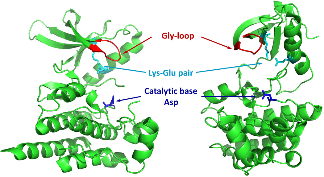
Our studies using RapR-FAK demonstrated the involvement of FAK in regulation of dorsal protrusions and allowed us to identify a previously unknown pathway for FAK-mediated control of membrane activity (Karginov et al., 2010a). This work exemplified RapR capabilities for specific temporal control of kinase activity, opening new possibilities for interrogating signaling events regulated by kinases. This technique should be readily applied to other protein kinases, as the catalytic domains of most known eukaryotic kinases are related in amino acid sequence, comprising a superfamily of eukaryotic protein kinases (ePKs) (Manning et al., 2002). The human kinome includes 478 ePKs out of 518 identified protein kinases. The rest of kinases are described as “atypical kinases”. Despite very little sequence similarity, even some atypical kinases display structural similarity to ePKs (Manning et al., 2002). The catalytic domain of protein kinases consists of an N-terminal β-sheet structured lobe and a predominantly α-helical C-terminal lobe. Essential elements of the catalytic domain that are involved in ATP binding and phosphate transfer include the glycine- or G-loop in the N-lobe a Lys-Glu pair that forms a salt bridge within the N-lobe, and an Asp residue in the C-lobe (Fig. 12) (Krupa et al., 2004). Mutation or structural modification of any of these elements will significantly affect the catalytic activity of a kinase. The conserved nature of the catalytic domains provides the basis for the broad applicability of RapR approach, as was demonstrated by successful regulation of three different kinases: FAK, Src and p38 (Karginov et al., 2010a).
Fig. 12.
Essential elements of the catalytic domain conserved in all ePKs. FAK catalytic domain structure is shown (PDB ID: 2IJM).
Rapamycin-regulated heterodimerization of FKBP12 and FRB has already been widely used in biological studies. Examples include regulated heterodimerization of receptor tyrosine kinases of the ErbB family (Muthuswamy et al., 1999), recruitment of proteins to the plasma membrane (Inoue et al., 2005) and regulation of gene expression (Liberles et al., 1997). Development of non-immunosupressive analogs of rapamycin enabled application of these approaches in live animals (Stankunas et al., 2003). In our studies we used similar regulatory elements and demonstrated very tight regulation of RapR-kinase activity not only with rapamycin but also with its non-immusupressive analogs (Karginov et al., 2010a).
Critical Parameters
The size of the insertion loop and the linkers connecting iFKBP to the catalytic domain are important for regulation of the kinase. Several alternative constructs should be tested to optimize regulation. One of the most critical parameters for the development of a RapR-kinase is the availability of reliable assay to test kinase activity in vitro and in living cells. Such an assay should be performed with the wild-type form of the kinase prior to testing a RapR-kinase, to ensure accurate and reproducible measurements. In general, an assay should allow you to activate the expressed kinase in living cells and then analyze the activity of the kinase.
Several critical controls should be performed to demonstrate that introduced iFKBP insertion affects only catalytic activity and does not perturb other properties of the kinase. The RapR-kinase localization and interaction with known binding partners should be tested. Other functions such as autoinhibitory regulation should be assessed as well.
The expression system is another important parameter. Ensure that you can achieve sufficient expression levels of your kinase. The presence of tags may affect expression, stability and localization of the target kinase. For the majority of kinases, transient expression in HEK293T cells should be the simplest option for biochemical characterization. Other cell lines can be used as well, but sufficient transfection efficiency and expression level should be ensured. Stable transfection should be considered for difficult to transfect cell lines. In general, expression of GFP- or mCherry-FRB is higher than for RapR-kinase. Thus, a weaker promoter can be used for stable co-expression of the FRB construct.
For each specific biological system, one should always assess the effect of rapamycin alone on the process that is being studied. In our studies, rapamycin had no effect on cell migration and membrane protrusion formation. If use of rapamycin is problematic, then non-immunosupressive analogs of rapamycin can be used (iRap, AP21967).
Troubleshooting
Potential problems, and means to address them, include:
iFKBP insertion does not regulate activity
If iFKBP insertion does not affect kinase activity, first test if there is rapamycin-mediated interaction between the modified kinase and FRB. If there no interaction or it is dramatically reduced, then most likely the insertion perturbed iFKBP structure. This is likely to happen when linkers connecting iFKBP and the catalytic domain are too short, as was demonstrated in our study. If rapamycin successfully induces interaction between the modified kinase and FRB, it indicates that the linkers are too long and iFKBP does not affect the dynamics of the catalytic domain. Alternatively, it is possible that the insertion loop is too long, positioning the iFKBP too far from the β-sheet core structure of the catalytic domain. In this case short linkers should be used and/or entire insertion loop should be replaced with iFKBP.
There is still significant background activity when the RapR-kinase is in the “off” state
It is possible that iFKBP insertion provides some level of control, but is incapable of inactivating the kinase completely. This may happen if the linkers connecting iFKBP to the catalytic domain are too long and/or if the insertion loop is too large. Complete removal of the insertion loop and/or shorter linkers may improve the regulation. This has been observed in our studies developing RapR-FAK. Alternative problems could be a high backround activity level in the particular kinase assay. The background level should be assessed using a kinase-inactive mutant of the RapR-kinase.
Anticipated Results
The method described in this unit should provide a guideline for development of rapamycin-regulated kinases. Using this guideline one should be able to identify the site for insertion of iFKBP, develop a strategy for iFKBP insertion, assess the regulation of the modified kinase by rapamycin or its analogs, and analyze the effect of kinase activation on cell behavior.
Time Considerations
Identification of the insertion site for iFKBP and primer design should take no more than one day. Cloning of iFKBP into a kinase and confirmation by DNA sequencing should not exceed 1 week. Transient transfection of the RapR-kinase and assessment of its activity will depend on the particular kinase assay procedure, but on average should not take longer than one week. Imaging of RapR-FAK activation as described here is conducted over a 90 min period, but similar imaging experiments can be extended to as long as 24 hours.
Footnotes
Copyright Permissions
Several figures from two previous publications are included in this manuscript. No special permission requests are required. However, all reprinted material is indicated and referenced in the figure legends as required by the publishers.
Literature Cited
- Bishop AC, Buzko O, Shokat KM. Magic bullets for protein kinases. Trends Cell Biol. 2001;11:167–172. doi: 10.1016/s0962-8924(01)01928-6. [DOI] [PubMed] [Google Scholar]
- Inoue T, Heo WD, Grimley JS, Wandless TJ, Meyer T. An inducible translocation strategy to rapidly activate and inhibit small GTPase signaling pathways. Nat Methods. 2005;2:415–418. doi: 10.1038/nmeth763. [DOI] [PMC free article] [PubMed] [Google Scholar]
- Karginov AV, Ding F, Kota P, Dokholyan NV, Hahn KM. Engineered allosteric activation of kinases in living cells. Nat Biotechnol. 2010a;28:743–747. doi: 10.1038/nbt.1639. [DOI] [PMC free article] [PubMed] [Google Scholar]
- Karginov AV, Zou Y, Shirvanyants D, Kota P, Dokholyan NV, Young DD, Hahn KM, Deiters A. Light Regulation of Protein Dimerization and Kinase Activity in Living Cells Using Photocaged Rapamycin and Engineered FKBP. J Am Chem Soc. 2010b doi: 10.1021/ja109630v. [DOI] [PMC free article] [PubMed] [Google Scholar]
- Krupa A, Preethi G, Srinivasan N. Structural modes of stabilization of permissive phosphorylation sites in protein kinases: distinct strategies in Ser/Thr and Tyr kinases. J Mol Biol. 2004;339:1025–1039. doi: 10.1016/j.jmb.2004.04.043. [DOI] [PubMed] [Google Scholar]
- Liberles SD, Diver ST, Austin DJ, Schreiber SL. Inducible gene expression and protein translocation using nontoxic ligands identified by a mammalian three-hybrid screen. Proc Natl Acad Sci U S A. 1997;94:7825–7830. doi: 10.1073/pnas.94.15.7825. [DOI] [PMC free article] [PubMed] [Google Scholar]
- Lyons PD, Dunty JM, Schaefer EM, Schaller MD. Inhibition of the catalytic activity of cell adhesion kinase beta by protein-tyrosine phosphatase-PEST-mediated dephosphorylation. J Biol Chem. 2001;276:24422–24431. doi: 10.1074/jbc.M011080200. [DOI] [PubMed] [Google Scholar]
- Manning G, Whyte DB, Martinez R, Hunter T, Sudarsanam S. The protein kinase complement of the human genome. Science. 2002;298:1912–1934. doi: 10.1126/science.1075762. [DOI] [PubMed] [Google Scholar]
- Muthuswamy SK, Gilman M, Brugge JS. Controlled dimerization of ErbB receptors provides evidence for differential signaling by homo- and heterodimers. Mol Cell Biol. 1999;19:6845–6857. doi: 10.1128/mcb.19.10.6845. [DOI] [PMC free article] [PubMed] [Google Scholar]
- Qiao Y, Molina H, Pandey A, Zhang J, Cole PA. Chemical rescue of a mutant enzyme in living cells. Science. 2006;311:1293–1297. doi: 10.1126/science.1122224. [DOI] [PubMed] [Google Scholar]
- Rivera VM, Ye X, Courage NL, Sachar J, Cerasoli F, Jr, Wilson JM, Gilman M. Long-term regulated expression of growth hormone in mice after intramuscular gene transfer. Proc Natl Acad Sci U S A. 1999;96:8657–8662. doi: 10.1073/pnas.96.15.8657. [DOI] [PMC free article] [PubMed] [Google Scholar]
- Sandhu GS, Precup JW, Kline BC. Rapid one-step characterization of recombinant vectors by direct analysis of transformed Escherichia coli colonies. Biotechniques. 1989;7:689–690. [PubMed] [Google Scholar]
- Spencer DM, Wandless TJ, Schreiber SL, Crabtree GR. Controlling signal transduction with synthetic ligands. Science. 1993;262:1019–1024. doi: 10.1126/science.7694365. [DOI] [PubMed] [Google Scholar]
- Stankunas K, Bayle JH, Gestwicki JE, Lin YM, Wandless TJ, Crabtree GR. Conditional protein alleles using knockin mice and a chemical inducer of dimerization. Mol Cell. 2003;12:1615–1624. doi: 10.1016/s1097-2765(03)00491-x. [DOI] [PubMed] [Google Scholar]


