

Abstract
A novel high-aspect-ratio penetrating microelectrode array was designed and fabricated for the purpose of recording neural activity. The array allows two dimensional recording of 64 sites in vitro with high aspect ratio penetrating electrodes. Traditional surface electrode arrays, although easy to fabricate, do not penetrate to the viable tissue such as central hippocampus slices and thus have a lower signal/noise ratio and lower selectivity than a penetrating array. In the unfolded hippocampus preparation, the CA1–CA3 pyramidal cell layer in the whole unfolded rodent hippocampus preparation is encased by the alveus on one side and the Schaffer tract on the other and requires penetrating electrodes for high signal to noise ratio recording. An array of 64 electrode spikes, each with a target height of 200 μm and diameter of 20μm, was fabricated in silicon on a transparent glass substrate. The impedance of the individual electrodes was measured to be approximately 1.5MΩ± 497kΩ. The signal to noise ratio was measured and found to be 19.4 ± 3 dB compared to 3.9 ± 0.8 dB S/N for signals obtained with voltage sensitive dye RH414. A mouse unfolded hippocampus preparation was bathed in solution containing 50 micro-molar 4-Amino Pyridine and a complex two dimensional wave of activity was recorded using the array. These results indicate that this novel penetrating electrode array is able to obtain data superior to that of voltage sensitive dye techniques for broad field two-dimensional neuronal activity recording. When used with the unfolded hippocampus preparation, the combination forms a uniquely capable tool for imaging hippocampal network activity in the entire hippocampus.
Keywords: Hippocampus, Microelectrode, Array, Propagation, MEMS
1. INTRODUCTION
Multi-site extra-cellular recordings are crucial to the study of large neuronal networks and multiple regions of activity simultaneously during an experiment. Voltage sensitive dyes have been developed to fluoresce with amplitudes modulated by cellular trans-membrane potential. These dyes, such as Di-8-Annepps and RH414 can be very useful in studying large areas of tissue at once, however they suffer from several problems. First, in the intact hippocampus (Derchansky et al, 2006, Kibler and Durand, 2011), activity from deep tissues such as the somatic layer are difficult to record without confocal microscopy due to pronounced light scattering. Secondly, dyes exhibit photo-toxicity with the high light intensity required to record high-speed images, causing noticeable extra-cellular response changes. In particular, phototoxicity renders imaging of epileptiform activity models such as low calcium and 4-AP difficult, as the spontaneous discharges can cease during high intensity light exposure. Finally, long term (over an hour) studies are difficult due to photo-bleaching, which decreases the fluorescence amplitude for each exposure taken.
The wide range of applications of microelectrode arrays (MEAs) in scientific research has resulted in the commercial availability of several array-based solutions. One of the most basic and widely used designs was first developed in 1972 by Thomas, et al. (1972). This simple solution involves evaporating a metal conductor onto glass and covering the interconnect traces and non-active sites with an insulating polymer, leaving the recording sites exposed. The result is an array of flat metal electrodes that can be pressed against tissue such as cardiac muscle, or used a as substrate for tissue culture.
The main drawback to this approach is that only a small number of electrically active neurons are in proximity of the desired recording sites. It has been shown that a penetrating electrode geometry will produce higher signal amplitude recordings in slices (Nordhausen et al., 1994). Previously reported devices, however (Charvet, et al., 2010; Heuschenkel et al., 2002; Nam et al., 2006), have low aspect ratio (essentially pyramidal at 1:1.5) electrodes which are not ideal for approaching active cells in the unfolded hippocampus preparation. Furthermore, the pyramidal shape constrains their usable height and array density, a tradeoff which leads to fabricated heights of approximately 50–100 μM (Thiebaud et al. 1999). As Charvet reported, it is possible to create electrodes with a higher aspect ratio by alternating isotropic and anisotropic etch procedures. However this method increases fabrication costs and results in electrodes with a lower overall aspect ratio than isotropic etching alone. (Charvet et al, 2010) Other recording array devices (Bhandari, et al,. 2009; Aziz, et al. 2009) achieve high aspect ratio electrodes but have large base diameters and do not offer a transparent substrate due to reliance on the Utah-style dicing saw fabrication process. A transparent substrate is preferable because it would allow the use of transmission microscopy for simultaneous imaging and electrical recording from neural networks, as well as optical stimulation protocols (Ghezzi et al., 2008).
Development was undertaken to create a multi-site, penetrating recording device for in vitro brain preparations of not only hippocampal slices, but a new unfolded hippocampus preparation. The unfolded hippocampus preparation has benefits over traditional slices in that it maintains longitudinal inter-neuronal processes which are thought to play a role in activity regulation, and the resulting preparation consists of a 2-dimensional pyramidal cell layer consisting of CA1 to CA3, versus a 1-dimensional layer of pyramidal neurons obtained from traditional slices. In this preparation, the pyramidal cell layer resides 180–270 microns from the alvear surface, too deep for traditional pyramidal penetrating electrode arrays to reach. The array described here was designed to overcome challenges by exhibiting the following design characteristics: 1) signal-to-noise ratio greater than 10dB, 2) high inter-electrode selectivity of local neuronal populations, 3) high aspect ratio (10) spikes reaching a height of 200 micrometers, 5) optically transparent, and 6) reusable. The MEA and amplifier system described below is the first known device to incorporate a penetrating high aspect ratio of 10 on a transparent substrate for multimodal neural recording in the rodent hippocampus preparation.
2. MATERIALS AND METHODS
2.1 Tissue Preparation
All experiments were performed in the CA1 and CA3 hippocampus regions of young (P10–P25) mice (Charles River, CD-1 strain). The experimental protocol was reviewed and approved by the Institutional Animal Case and Usage Committee. Mice were anesthetized using ethyl ether and decapitated. The brain was rapidly removed and chilled in ice cold (3–4° C) sucrose-rich artificial cerebro-spinal fluid (sACSF) consisting of (mM): Sucrose 220, KCl 3.75, NaH2PO4 1.25, MgSO4 2, NaHCO2 26, CaCl2 2, and Dextrose 10 (pH 7.4) for approximately 10 seconds. Following removal, the brain was sectioned twice, removing the cerebellum and separating the two hemispheres by cutting midsagitally. For unfolded hippocampus preparations, the brain was quickly moved onto a moistened, chilled filter paper following the same methodology as described for brain slice preparations (Teyler, 1980). Chilled oxygenated sucrose rich ACSF was dripped frequently onto the hippocampus to maintain moisture and allow some oxygenation. The cerebellum was removed and the brain was hemisectioned by a razor blade. The hippocampus was freed from the septum and entorhinal region using either dorsal or ventral approach (Teyler, 1980). Both rounded ends of the hippocampus were trimmed in a line perpendicular to the longitudinal axis, resulting in a slab approximately 3mm wide. Similar to Wu et al. (Wu et al., 2002), the dentate gyrus (DG) was unrolled by sliding a sharp glass electrode along the line of the fissure and carefully unrolling the DG using a combination of glass and tungsten wire loops. The resulting preparations were immediately immersed in oxygenated normal ACSF (nACSF) consisting of (mM): NaCl 124, KCl 3.75, KH2PO4 1.25, CaCl2 2, MgSO4 2, NaHCO3 26, Dextrose 10 (pH 7.4), and incubated at room temperature for at least 60 minutes before being transferred to a submerged-tissue perfusion chamber and discarded 6–8 hours post incubation. Experiments were conducted using nACSF with 50μM 4-AminoPyradine (4-AP) obtained from Sigma.
2.2 Electrical Recording
Orthodromic, evoked field potentials were recorded in the stratum pyramidale and basal dendritic area of in vitro mouse hippocampus preparations using both glass microelectrodes (3–10MΩ) filled with 150mM NaCl solution and individual microelectrode array spikes (1–2MΩ). Square pulses (100μs, 100μA, 0.5–0.2 Hz were used to evoke orthodromic potentials in the CA1 and CA3 region of the hippocampus via a sharp-tipped Tungsten stimulating electrode. Evoked and spontaneous somatic activity was recorded and later quantified. The signal to noise ratio (SNR) was calculated as shown in (1) where P-PSig is the peak-to-peak signal amplitude of the tissue response, and P-PNoise is the peak-to-peak noise amplitude recorded in a time window with no neural activity.
| (1) |
2.3 Optical Recording
The hippocampus preparation was stained with the fast voltage-sensitive styryl dye RH-414 (N-(3-(triethylammonium)propyl)-4-(4-(p-diethylaminophenyl)-butadienyl)-pyridium dibromide; Molecular Probes) at 200 μM in a micro superfusion chamber for 15 minutes in a darkened room. Excess stain was washed away with dye-free ACSF before recording. The preparation was then transferred to a submerged recording chamber. Similar current stimuli are to be used for optical and electrical recordings. At the same time, a glass microelectrode filled with 150 mM NaCl (resistance 3–10 MΩ) was inserted into the mossy fiber cell layer, using a dissecting stereomicroscope for guidance. Extra-cellular field potential recordings were simultaneously performed during the imaging to assess the viability of the preparation and to monitor the amplitude of evoked responses. The tissue was illuminated via epi-illumination using an inverted Nikon Diaphot culture microscope fitted with a low noise DC-powered tungsten-halogen lamp (100W, 12 V). Stimulation, shutter control, bath circulation pause to reduce artifact during optical recording, and bias adjustments were controlled automatically though a custom program running on a digital stimulator controller (PG4000, Neuro Data Instrument). Fluorescence evoked was measured (interface filter: 535 ± 25 nm, dichroic mirror 580 nm; barrier filter 590 nm) at each scanning point in a 16 × 16 photodiode array (Hamamatsu C4675-102) and amplified with a custom amplifier and low pass filter with a cutoff set to 1 KHz. The imaging objective (10×, 0.5 NA) results in a spatial resolution of each element of 137 × 137 μm. Current signals from each photodiode were converted to voltage, amplified, filtered, digitized, and then sampled at 500–1500 Hz. Time averaging was not used in the assessment and measurement of the SNR of either the optical or electrical devices. Typically a 1–2% change in fluorescence was seen during neuronal firing.
2.4 Microelectrode Array Design and Construction
The array was designed with thin, high aspect ratio spikes that are terminated with sharp tips for easy and non-tearing insertion resulting in minimal tissue damage. The spike tips have electrically active surfaces with impedance appropriate for neural recording. The non-active areas are coated with a biocompatible insulation material, and the substrate is transparent glass. The array is designed to provide an adequate density of recording sites, and such that the active area is large enough to cover the area of interest. Based on the structure and size of the hippocampus, the distance between spike centers is 400 μm in the x direction and 300μm in the y direction in a pattern of 8×8 spikes, resulting in an active area of 2.1mm by 2.8 mm and 64 recording channels. The spikes are to be 20 μm wide and 200 μm high.
The microelectrode array was designed and fabricated at the NASA Goddard Space Flight Center Detector Development Lab, Greenbelt, MD. The array chip was built on a transparent Pyrex glass substrate with thin gold leads from each spike to bond pads on the outer edges of the 10×10mm chip. The chip was then glued and wire bonded to an open-top 137 pin ceramic PGA package. Before mounting the chip in the package, a 10mm diameter hole was laser cut into the center of the package, allowing inverted microscopy and fluorescence imaging of the tissue while mounted on the array.
Construction of the array began with a 10mm Pyrex wafer patterned with resist to form bonding pads, spike bottoms, and spike traces and etched in 7:1 buffered hydrofluoric acid solution to create recesses. The recesses were found to be necessary in order to prevent voids around deposited metal during the anodic bonding process. Next a highly doped silicon wafer of a conductivity of at least 0.1 Ω-Cm was thoroughly cleaned and then placed in an oxidizing furnace to build up a thermal silicon oxide of approximately 5000Ǻ thickness. The oxide was then masked and etched in a 7:1 buffered hydrofluoric acid solution down to the silicon in the locations of the bottom of the spikes and wire bonding pads. Then a thin layer of chrome gold alloy was evaporated onto the glass and gold wafers so that it rose approximately 500Å above the glass etch and silicon oxide depths. The excess metal was lifted off and the wafers thoroughly cleaned before being anodically bonded with the gold sides facing together. The temperature of the anodic bonding process was set at just below the eutectic temperature of the gold and silicon so that good electrical bonds were formed from the silicon to the traces etched into the Pyrex backing. The bonded wafers were then placed in a warmed 25% TMAH anisotropic etch solution until the silicon was thinned to the desired spike height of 200μm. A tip mask was then exposed on the silicon and sharp tips were etched into the silicon using an anisotropic ion etch. A photoresist pattern was exposed on the silicon and gold was again evaporated on the wafers and lifted off of the non-desired areas. Gold was left on the spike tips and wire bonding pad locations to be used as contacts and active conducting area. Finally, a 50μm thick resist was spun on the silicon and used as a deep RIE (reactive ion etch) mask for the final ion-based preferential etch of the silicon wafer down to the oxidation layer. Using the same photomask, an array of 8 sacrificial pillars was patterned encircling each electrode tip to aid in the deep reactive ion etch (DRIE) process. The purpose and effectiveness of these pillars is discussed below. The oxide formed on the silicon wafer in the first step, which had been sandwiched between the Pyrex and conducting silicon, acts as an etch stop and a passivation layer over the traces in the Pyrex after they are exposed by the DRIE Bosch process. A final biocompatible insulating layer, 3–4μm of parylene was coated onto the entire chip and laser ablated from the bonding pads and spike tips. This conformal parylene coat helps ensure biocompatibility and insulation during experimentation. A diagram of this entire process is shown in Fig 1. Each array was wire-bonded and mounted in the ceramic PGA package carrier (See figure 2A and 2B). Note one example of a fallen spike in figure 2B. Figure 2.C shows how the unfolded hippocampus preparation is mounted to the array for recording in pyramidal CA1–CA3.
Fig. 1.

Simplified assembly process showing a single spike electrode.
Fig. 2.
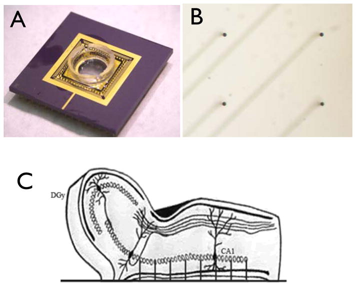
A) Completed and mounted 64-ch electrode array with perfusion chamber attached. B) Micrograph image of quadrant subset of array electrodes showing 4 electrodes and traces below. C) Side-view diagram of unfolded hippocampus preparation placement on electrode array.
2.5 Microelectrode Array Amplifier System
A 64-channel low noise amplifier circuit was designed and built to be located as near as possible to the recording sites in order to minimize noise coupling and crosstalk between channels. Each amplifier section was designed with a low input bias current and voltage noise, along with a low-pass Sallen-key filter with a bandpass of 0.1 Hz to 4kHz (Fig. 3A). This low-pass post filter was designed to reduce noise, prevent sample aliasing in the acquisition process, and act as a buffer with which to drive cabling and its associated capacitances to the acquisition processor. In addition to the amplification circuitry, stimulus artifact blanking circuitry was integrated in order to reduce the recovery time constant generated by the monopolar, monophasic stimuli typically utilized in experiments. The stimulus artifact blanking circuit allows adjustment of onset delay and blanking duration given a trigger, as well as the blanking level (circuit not shown.)
Fig. 3.

A) Schematic of a single amplifier circuit. B) Schematic of the protection circuit C) Picture of the final assembled system. Onboard low noise power supply delivered power with a noise of 136μV P-P under load, total input referred noise of amplifier and array system was measured to be 56μV RMS
Because this amplifier system will be used in close proximity to flowing ACSF solution, a spilled water detection circuit was integrated into the main board to prevent electrolytic corrosion by shutting down power if water is detected. The sensor system is comprised of a set of parallel sense wires that run around the board, as well as the detection and shutdown circuit shown in Figure 3B. The gain and bandwidth of the amplifier (Fig. 3C) and array combination was tested in a saline bath with a Ag-Ag-Cl electrode using a sinusoidal waveform frequency sweep and found to be 100x as designed with a bandwidth of 0.5Hz to 3.5kHz ± 0.8%.
3. RESULTS
3.1. Electrode Array Fabrication
Fabrication of the array was a significant challenge, with a 40% yield of 12 chips per wafer, and of those, 36% with all spikes remaining intact, final yield 14%. The spike electrodes were stress tested by placing discarded mouse brain tissue such as the cerebellum on to the spike area and, using a micromanipulator, maneuvering the tissue in a linear motion across the spikes in a simulated worst-case-scenario. Out of 8 arrays tested, none incurred fractured electrodes as a result of the tissue stress test. Despite this, care must be taken during manipulation of the tissue to ensure that no other objects come in contact with the array’s micro spikes. It was found the spikes were readily damaged by contact with tungsten stimulating electrodes or other stiff object contact. Spike electrode impedance was measured to be 1.5M Ω ± 497 kΩ at 1 kHz. Final average electrode spike height was 244μm ± 6.2 μm SD. Within a single array, the electrode spike height varied only ± 1.6 μm SD. Pyramidal sharp electrode tips had a width and height of 20 μm. Spike to spike spacing variability was measured to be less than 10 μm. Average sacrificial pillar leftover height (of all leftover pieces still attached to the substrate) was 20 μm, shallow enough to not interfere with tissue penetration of the main electrodes. On average, there were 5 sacrificial pillar pieces left per array. An electron micrograph of the electrode spike tip during processing is shown in Figure 4A.
Fig. 4.

A) Scanning electron micrograph of electrode spike tip during fabrication B) Scanning electron micrograph of a sacrificial pillar array test showing the progression of thin sacrificial pillars being undercut and falling early toward the top, and thicker sacrificial pillars not falling near the bottom. In between, sacrificial pillars are undercut sufficiently at the end of processing to be washed away leaving the desired electrode spike undamaged. C) Electron micrographs of various sacrificial pillar diameter and spacing tests. 1) Sacrificial pillars initially protected center electrode, but were undercut too soon, leaving it unprotected, at which time thinning rate increased on central spike. Note: short pillar to the right is created by the horizontal mask of a fallen sacrificial pillar. 2) Undercut sacrificial pillars and preserved electrode (center). 3) Excessively tight sacrificial pillar spacing prevents undercut at the desired etch depth and causes them to merge.
3.2. Sacrificial Pillars
In the course of fabrication it was necessary to define a ring of 8 ‘sacrificial pillars’ surrounding the electrode spikes to protect them from negatively sloped sidewalls during the DRIE etch process. A test DRIE resist mask was created with a matrix of varying width and spacing of eight sacrificial pillars surrounding each electrode spike (Fig. 4B). Sacrificial pillar diameter ranged from zero to thirteen microns in steps of two microns along rows and center-to-center pillar spacing from the central protected spike ranged from 21.5 micrometers to 36.4 micrometers along columns. Test DRIE etches of the desired depth were performed in order to determine the ideal sacrificial pillar arrangement which would protect the electrode spike from over-etching and also result in completely undercut or sufficiently thinned sacrificial pillars at the end of the etch so they could be washed away in a rinse, leaving only freestanding electrode spikes. The thicknesses of the pillars along with the pillar spacing determined the amount of electrode protection as well as when the pillars would be completely under-cut at the end of the DRIE etch as desired. If the pillars were too thin, they would fall early (Fig. 4C1) However if the pillars were too thick they would not be sufficiently undercut by the time the desired DRIE etch depth was reached (Fig. 4C3). An analysis of the test samples made using the desired etch height of 200 micrometers revealed that a ring of 8 sacrificial pillars of diameter of 15 microns and spaced 55.75 microns from the center of the electrode spike performed well to protect the central spike and at the same time, by the end of the etch the sacrificial pillars were completely or nearly completely undercut, to the extent that a wash agitation could wash them away (Fig. 4C2). This manufacturing design could nearly eliminate excessive passivation erosion of the desired spike electrode, while maintaining etch conditions that mostly eliminate grass formation during the etching process.
3.3. Neural Activity Measurement
In order to test the ability of the array to map neural activity, the unfolded hippocampus preparation was used since it takes advantage of the array’s ability to record potentials in both the transverse and longitudinal direction in the hippocampus (Kibler and Durand, 2011). Optical imaging of CA1–CA3 evoked potentials in 50μM 4-AP was performed as a baseline comparison of signal quality. These signals (Fig. 5B) were compared with extracellular field potential recordings from the microelectrode array (Fig. 5A). SNR analysis of six experiments showed that significant photo-bleaching occurred over two minutes with the RH-414 optical imaging technique, with the SNR decreasing from 5.3 ± 2.3 dB to 0.7 ± 0.5 dB. Comparatively, no signal degradation was seen with the microelectrode array recording showing a 20.7 ± 1.7 dB SNR at the onset and ending with 32.4 ± 1.5 dB measurements (Fig. 5C).
Fig. 5.

A) Unfiltered recording from array spike in the CA3 pyramidal cell layer. B) Unfiltered recording from voltage sensitive dye in the CA3 region. C) Comparison of optical dye recording and penetrating microelectrode array recording SNRs over two minutes of extracellular potentials in 50μM 4-AP in the CA3 of the hippocampus slice preparation (n=5).
3.4. Multi-channel Recordings of neural activity propagation
In order to obtain a control with which the recording array signals could be compared, a series of glass micropipette recordings were performed in 50 μM 4-AP solution. Upon application of 4-AP, spontaneously occurring potentials were observed in the CA3 region of the unfolded hippocampus preparation. These potentials are generally referred to as interictal-like events (ILEs) similar to potentials recorded in the transverse slice (Avoli, 1991). These 4-AP induced ILEs were recorded from multiple simultaneous locations along the CA3 as shown in Fig. 6. Recording electrodes were placed at a depth of 200–300μm and a wave of activity in the somatic region of CA3 was observed. This ILE wave was recorded for later comparison with array recording results and is characterized in details in Derchansky et al., 2006 and Kibler and Durand, 2011.
Fig. 6.

Spontaneously generated wave propagating along the CA3 region in the unfolded mouse hippocampus in 50 μM 4-AP. Dashed line indicates propagation speed of 0.11m/s. Trace one is a recording from the temporal pole of the CA3, the trace at location six is recorded from the septal pole of the unfolded hippocampus preparation, and the traces in between are recorded along the longitudinal axis. Peak initial wave amplitude is indicated by arrows.
The recording array system was then used to record spontaneous 4-AP induced epileptiform activity in the somatic layer of the unfolded hippocampus. The tissue was positioned so that recording electrodes reached CA1–CA3 hippocampal regions along the length of the unfolded preparation. Spontaneous interictal-like wave activity was recorded in the CA3 and CA1 regions as shown in Fig. 7. Data were acquired at a rate of 4–5 kframes/sec and spatially interpolated for clarity in the figure. Data were then filtered with a low-pass filter to 150 Hz. The data recorded by the array from the unfolded hippocampus preparation reveal propagation and spontaneous activity in the CA1 and CA3 regions of the hippocampus. A wave-like ILE event can be seen traveling along CA3 in Figure 7 This wave-like event closely follows that seen from the previously described class micropipette control and travels at the speed of 0.1 ±0.024 m/s N=5, matching that obtained with the glass microelectrode in figure 6. Figure 7 reveals a complex pattern of epileptiform propagation within the CA1–CA3 regions along the hippocampus not observed with micropipettes. Activity initiates at the temporal pole but does not immediately travel down the CA3 in a sharp wave, instead broadening out over time before reaching the septal pole. The second wave of the burst, however, maintains a somewhat sharp peak as it travels along the CA3 region. In the final burst, the extracellular potential wave maintains a sharp profile along the entire CA3. Of particular interest is the propagation speed for all three waves, which is graphically represented by the dashed line in Figure 7.C, and is similar from temporal initiation to septal termination. Use of the penetrating spike recording array also reveals group activity in CA1 near its connection to the entorhinal cortex. The acquisition time for the data recorded with the array system was approximately 5 seconds, whereas traditional repositioning of the glass recording micropipette along CA3 required about 30 minutes to ensure quality recording and proper depth, over which time the spontaneous propagation may change slightly, causing artifacts.
Fig. 7.

A) Extracellular voltage map obtained from the array with 4-AP (50μM)-induced spontaneous inter-ictal like complex activity in the hippocampus, 5ms per frame. Black line in first frame indicates location of sampled channels for trace data in C. B) Placement diagram of recording frame in A. on unfolded hippocampus and scale color bar. C) Voltage recorded by the line of spike along the CA3 layer from the right third of the image displayed in A, sampled top to bottom (propagation speed is 0.1m/s)
4. DISCUSSION
Described above is a novel penetrating microelectrode array device and amplifier system that achieves a penetration depth of ~250 μm with high aspect ratio electrode spikes, a transparent substrate, and biologically relevant bandwidth and sensitivity. During array fabrication, most processing steps such as the anodic bonding of wafers, thinning, and tip patterning proceeded without significant problems following parametric tuning. However, the desired high aspect ratio of electrode spikes (10), combined with their broad inter-spike spacing, presented significant difficulties during the DRIE Bosch process etch procedure. Tuning etch parameters such that a ~200 μm etch of silicon to the silicon oxide layer could be performed without formation of silicon ‘grass’ at the etch bottom resulted in a negative sidewall angle of the electrode spikes. At the end of the etch process, the spikes had significantly thinned bases, down to ½ of their original diameter. This thinning produced spikes that had an apical diameter of 20 μm as designed, but at the base as little as 10 μm of pillar remained. It was theorized that the lack of sloping in some areas was caused by a shielding effect from non-perpendicularly approaching ions of nearby structures that formed as etching progressed. If the desired electrode pillars could be shielded from non-perpendicularly approaching ions during the etch, perhaps they could also be spared from thinning. An experiment was devised to test the shielding effect of ‘sacrificial’ pillars arranged in a ring surrounding the desired electrode. These sacrificial pillars, in theory, would absorb excess erosion caused by non-perpendicularly approaching etch ions while allowing the desired central electrode pillar which they surround to be etched with straight sidewalls. Such an arrangement successfully protected the desired electrode spike while minimizing grass formation, due to the fact that a more aggressive etch cycle could be used while preserving the pillar sidewalls. In addition, the silicon oxide layer that is reached in device fabrication during this step acts as an etch stop, allowing a few more cycles to cut any small grass formations and sacrificial pillars down. The methods described herein allowed for the creation of high aspect ratio, broadly spaced electrode spikes with reduced silicon grass formation and negative sidewall slope.
The electrode array described above has several desirable features for in-vitro work and is particularly well-suited for two-dimensional recording from pyramidal cells of the unfolded rodent hippocampus preparation. Its electrode height allows for penetration deep inside the tissue while its transparent substrate allows for optical recording and stimulation while the electrodes are recording neural activity. The combination of the recording array and the unfolded hippocampus allows detailed two-dimensional electrophysiological investigation of the hippocampus neural network which was previously difficult, unreliable, or impossible. The devices exhibited good durability to repeated application and removal of neural tissue, on average withstanding 10 individual experiments. The typical damage was caused by accidental impact with glass and tungsten electrodes during the course of experimentation. To minimize the risk of accidental electrode damage, the tissue was float-positioned above the array and allowed to settle into the array via a brief drawdown of the bath level in the array chamber. Hydrostatic forces proved to be sufficient to facilitate electrode penetration. A grid of thin nylon wires, similar to that used in common superfusion baths was placed above the tissue to ensure flat contact, however after electrode penetration the tissue remained in place without assistance. The ceramic carrier package and device materials, passivation, and sealant support standard sterilization procedures for re-use in sensitive long-term experiments and on-device tissue cultures. For sterilization insensitive acute experiments, the array was rinsed with de-ionized water and ethanol after each experiment. The data presented herein show that the electrode array system recordings agree with those from traditional glass micropipettes, as expected, however the use of the recording array presents several benefits over traditional tools. The recording array acquires signals from all 64 channels nearly simultaneously, allowing for robust acquisition of single events as well as slowly changing repetitive events. The precise spacing of the array electrodes as patterned removes variability inherent in manually placing micropipettes in various tissue locations in an attempt to map the same activity. The penetrating nature of the electrode spikes and their uniform height allows for targeted recording of the hippocampal pyramidal cell layer, as opposed to wide field voltage sensitive dye microscopy which can not. Furthermore, the transparent substrate, high aspect ratio electrode spikes, and design-adjustable electrode height enable use of this design for study of other applications such as hippocampal slices, cortical sections, and retinal preparations. Although the array was designed primarily for in-vitro preparations, it could be adapted for in-vivo applications by providing an interface in the back of the array thereby providing an ideal tool for combined optical-electrical recording and stimulation. In addition, the signal-to-noise ratio for the recording array was significantly greater than that of the traditional voltage sensitive dye and high speed photodiode array recording system, and comparable to commercially available MEA solutions (Steidl et al., 2006). However, the advantage of the high aspect ratio electrode is that recordings can be obtained deep inside the tissue.
One limitation of the array is its relatively high source impedance averaging 1.5MΩ. This impedance is a function of the electrode tip area, and the surface roughness of gold deposition. It might be desirable to decrease the electrode impedance in the future using roughened polysilicon (Paik et al., 2003), sonicoplated platinum black (Desai et al., 2010), or nanoflake (Kim et al., 2010) coating. Referring to Figure 1, the fabrication process for the array wafers can be broken down into 4 days, with day one covering steps 1 and 2, day two covering steps 3 and 4, day three covering 5–7, and day four covering step 8 and parylene coating with selective removal. Although the fabrication procedure contains numerous steps, the complexity does not exceed that seen in commercial transparent-substrate 3D electrode solutions such as the BioMEA product (Charvet, 2010). Also, because the presented array does not require alternating anisotropic and isotropic etch procedures to achieve high aspect ratio electrodes, processing time may be reduced.
5. CONCLUSION
The microelectrode array shows greatly improved SNR and recording durations than seen with fluorescent optical imaging. Furthermore, spontaneous activity that could not be reliably observable with the optical method is now easily recorded with high SNR and temporal resolution. The described device achieved the desired goals of high aspect ratio electrodes, transparent substrate, and reusability. Its electrode placement is ideal for recording from rodent hippocampus slices and unfolded hippocampus preparations. The array electrophysiological results obtained in ACSF with the addition of 4_AP are consistent with those recorded using traditional glass micropipettes and benefit from being collected simultaneously across the tissue. This array can be used for two-dimensional mapping of spontaneous ictal and interictal epileptiform activity in the hippocampus, and is applicable in other studies such as measuring the network response of optically-sensitive normal and transfected neural tissue, and studying whole-hippocampus synaptic plasticity responses to local stimuli. In combination with the unfolded hippocampus preparation, this new array and amplifier system should be helpful to improve understanding of hippocampal ictogenesis and network processing.
Highlights.
A novel penetrating micro-electrode recording array system is developed and detailed for recording from unfolded hippocampus preparations.
This micro-electrode array is uniquely able to record from the pyramidal cell layer in both the transverse and longitudinal directions.
High-fidelity imaging of two-dimensional wave propagation in the hippocampus is demonstrated using the array.
Acknowledgments
Financial support for this proposal was provided by NIH grant R01NS40785
Footnotes
Publisher's Disclaimer: This is a PDF file of an unedited manuscript that has been accepted for publication. As a service to our customers we are providing this early version of the manuscript. The manuscript will undergo copyediting, typesetting, and review of the resulting proof before it is published in its final citable form. Please note that during the production process errors may be discovered which could affect the content, and all legal disclaimers that apply to the journal pertain.
References
- Aghajanian GK, Rasmussen K. Intracellular studies in the facial nucleus illustrating a simple new method for obtaining viable motorneurons in adult rat brain slices. Synapse. 1989;3(4):331–8. doi: 10.1002/syn.890030406. [DOI] [PubMed] [Google Scholar]
- Aziz JNY, Abdelhalim K, Shulyzki R, Genov R, Bardakjian BL, Derchansky M, Serletis D, Carlen PL. 256-Channel Neural Recording and Delta Compression Microsystem With 3D Electrodes. IEEE J of Solid-State Circuits. 2009;44(3):995–1005. [Google Scholar]
- Bhandari R, Negi S, Reith L, Normann RA, Solzbacher F. A novel masking method for high aspect ratio penetrating microelectrode arrays. J Micromechanical Microengineering. 2009;19:035004. [Google Scholar]
- Charvet G, Billoint O, Gharbi S, Heuschkel M, Georges C, Kauffmann T, Pellieeier A, Yvert B, Guillemaud R. A modular 256-channel micro electrode array platform for in vitro and in vivo neural stimulation and recording: BioMEA. Conf Proc IEEE Eng Med Biol Soc. 2010;2010:1804–7. doi: 10.1109/IEMBS.2010.5626403. [DOI] [PubMed] [Google Scholar]
- Charvet G, Rosseau L, Billoint O, Gharbi S, Rostaing J-P, Joucla S, Trevisiol M, Bourgerette A, Chauvet P, Moulin C, Goy F, Mercier B, Colin M, Spirkovich S, Fanet H, Meyrand P, Guillemaud R, Yvert B. BioMEA: A versatile high-density 3D microelectrode array system using integrated electronics. Biosensors and Bioelectronics. 2010;25:1889–1896. doi: 10.1016/j.bios.2010.01.001. [DOI] [PubMed] [Google Scholar]
- Derchansky M, Rokni D, Rick JT, Wennberg R, Bardakjian BL, Zhang L, Yarom Y, Carlen PL. Bidirectional multisite seizure propagation in the intact isolated hippocampus: The multifocality of the seizure “focus”. Neurobiology of Disease. 2006;23:312–328. doi: 10.1016/j.nbd.2006.03.014. [DOI] [PubMed] [Google Scholar]
- Desai SA, Rolston JD, Potter SM. Improving impedance of implantable microwire multi-electrode arrays by ultrasonic electroplating of durable platinum black. Front Neuroengineering. 2010;3:5. doi: 10.3389/fneng.2010.00005. [DOI] [PMC free article] [PubMed] [Google Scholar]
- Ghezzi D, Menegon A, Pedrocch A, Valtorta F, Ferrigno G. A Micro-electrode array device coupled to a laser-based system for the local stimulation of neurons by optical release of glutamate. J Neurosci Methods. 2008;175(1):70–78. doi: 10.1016/j.jneumeth.2008.08.003. [DOI] [PubMed] [Google Scholar]
- Heuschenkel MO, Fejtl M, Raggenbass M, Bertrand D, Renaud P. A three-dimensional multi-electrode array for multi-site stimulation and recording in acute brain slices. J Neurosci Mehtods. 2002;114(2):135–48. doi: 10.1016/s0165-0270(01)00514-3. [DOI] [PubMed] [Google Scholar]
- Kibler AB, Durand DM. Orthogonal Wave Propagation of Epileptiform Acitvity in the Planar Mouse Hippocampus in vitro. Epilepsia. 2011 doi: 10.1111/j.1528-1167.2011.03125.x. (in press) [DOI] [PMC free article] [PubMed] [Google Scholar]
- Kim J, Kang G, Nam Y, Choi Y. Surface-modified microelectrode array with flake nanostructure for neural recording and stimulation. Nanotechnology. 2010;21(8):085303. doi: 10.1088/0957-4484/21/8/085303. [DOI] [PubMed] [Google Scholar]
- Kloosterman Fabian, Peloquin Pascal, Lueng Stan. Apical and Basal Orthodromic Population Spikes in Hippocampal CA1 In Vivo Show Different Origins and Patterns of Propagation. J Neurophysiol. 2001;86:2435–2444. doi: 10.1152/jn.2001.86.5.2435. [DOI] [PubMed] [Google Scholar]
- Nam Y, Wheeler BC, Heuschkel MO. Neural recording and stimulation of dissociated hippocampal cultires using mixcrofabricated three-dimensional tip electrode array. J Neurosci Methods. 2006;155(2):296–9. doi: 10.1016/j.jneumeth.2006.01.014. [DOI] [PubMed] [Google Scholar]
- Nordhausen CT, Rousche PJ, Normann RA. Optimizing recording capabilities of the Utah Intracortical Electrode Array. Brain Res. 1994 Feb 21;637(1–2):27–36. doi: 10.1016/0006-8993(94)91213-0. [DOI] [PubMed] [Google Scholar]
- Paik Seung-Joon, Yonghwa Park, Cho Dong-il. Roughened polysilicon for low impedance microelectrodes in neural probes. J Micromechanics and Microengineering. 2003;13:373–379. [Google Scholar]
- Skrede KK, Westgaard RH. The transverse hippocampal slice: a well-defined cortical structure maintained in vitro. Brain Res. 1971;35:589–593. doi: 10.1016/0006-8993(71)90508-7. [DOI] [PubMed] [Google Scholar]
- Steidl E-M, Neveu E, Buisson B. The adult hippocampal slice revisited with multi-electrode arrays. Brain Res. 2006 June 22;1096(1):70–84. doi: 10.1016/j.brainres.2006.04.034. [DOI] [PubMed] [Google Scholar]
- Teyler TJ. Brain Slice Preparation: Hippocampus. Brain Res Bull. 1980;5:391–403. doi: 10.1016/s0361-9230(80)80009-8. [DOI] [PubMed] [Google Scholar]
- Thiebaud Pierre, et al. An array of Pt-tip microelectrodes for extracellular monitoring of activity of brain slices. Biosens Bioelectron. 1999;14(1):61–5. doi: 10.1016/s0956-5663(98)00098-0. [DOI] [PubMed] [Google Scholar]
- Thomas, et al. A miniature microelectrode array to monitor the bioelectric activity of cultured cells. Experimental Cell Research. 1972;74(1):61–66. doi: 10.1016/0014-4827(72)90481-8. [DOI] [PubMed] [Google Scholar]
- Wu C, Shen H, Luk WP, Zhang L. A Fundamental Oscillatory State of Isolated Rodent Hippocampus. J Physiol. 2002;540.2:509–527. doi: 10.1113/jphysiol.2001.013441. [DOI] [PMC free article] [PubMed] [Google Scholar]