Abstract
Mechanical details as well as electrical models of FDR (frequency domain reflectometry) sensors for the measurement of the complex dielectric permittivity of porous materials are presented. The sensors are formed from two stainless steel parallel waveguides of various lengths. Using the data from VNA (vector network analyzer) with the connected FDR sensor and selected models of the applied sensor it was possible obtain the frequency spectrum of dielectric permittivity from 10 to 500 MHz of reference liquids and soil samples of various moisture and salinity. The performance of the analyzed sensors were compared with TDR (time domain reflectometry) ones of similar mechanical construction.
Keywords: FDR, TDR, dielectric permittivity, dielectric spectroscopy, soil moisture, soil salinity
1. Introduction
The requirements for fast, reliable and automated spatially distributed soil water content monitoring are not fully satisfied by the current commercially available technology measurements. The reasons for that are high price of commercially available TDR meters working in the frequency range up to 1 GHz, the need for site specific calibrations of FDR meters, especially for heavy and saline soils, or problems with disposal of radioactive elements when the neutron scattering method is used. Scientists and engineers are conducting research and building prototypes to develop new soil water and salinity sensors and their physical models to increase measurement selectivity, accuracy, ease of operation and availability, as well as to make them economically accessible for mass applications. Nondestructive and in situ measurements of soil water content and salinity are fundamental in many agricultural applications including hydrology, precision agriculture and irrigation scheduling [1–3]. The idea of applying FDR sensors working in the frequency range above 150 MHz, which is the upper frequency limit of currently available sensors, and reaching 500 MHz, seems to be promising, especially to achieve more universal calibration than current FDR sensors and lower cost than the current TDR meters [4].
At present, several methods are considered suitable for continuous soil water monitoring at the point scale with minimum soil disturbance. Such methods are based on the dielectric properties of soil and the propagation characteristics of electromagnetic (EM) waves in the soil, which change with water content and salinity. A review of soil moisture and electrical conductivity measurement methods, including the dielectric methods at different spatial and temporal scales is presented in [4]. The relationship between the real part of the permittivity and soil volumetric water content is strong for the quartz-dominated soils [5]. Although quartz-dominated materials show negligible frequency dependence of dielectric properties, some clay minerals present dielectric dispersion [6–8]. As a result, the relationship between soil moisture and electrical conductivity depends on the operating frequency of the applied sensor. The least frequency dependence occurs above 500 MHz [7]. Also, accurate measurement of the real part of the soil complex dielectric permittivity is required to fully characterize its relationship with soil moisture in the frequency domain.
The aim of the study is to analyze the influence of soil water content and electrical conductivity/salinity on the on the complex dielectric permittivity of soil measured by a developed FDR (Frequency Domain Reflectometry) sensor and the measurement setup. The sensor and its physical models are used to measure the complex dielectric permittivity in the 10–500 MHz frequency range. The measurements are made in laboratory conditions using specialized equipment not suitable for field use. The presented study is an initial step in works on field sensors and a prototype of a field meter for the measurement of dielectric permittivity of soil in this frequency spectrum and hopefully up to 1 GHz.
2. Sensor Description and Measurement Tools
The applied dielectric sensors were built with two stainless steel rods of 2 mm in diameter, 13 mm separation distance and lengths of 1, 2 and 3 cm (Figure 1—left). The interface between the coax cable and stainless steel rods was constructed to minimize the impedance discontinuity (Figure 1—right).
Figure 1.
Two wire stainless steel rod FDR probes (left), the scheme of internal details (middle) and the interface between coaxial and parallel waveguides (right).
The mechanical construction of these sensors is similar to the FP/m type manufactured in IA PAS (Lublin, Poland) working with the TDR technique [9]. TDR probes with such short length are not used because of timing restrictions imposed by this measurement method. The presented FDR probes with parallel 1–3 cm length rods may fill the gap for dielectric sensors between open-ended coax [10] and TDR sensors. The TDR measurements give averaged information about the apparent dielectric permittivity and electrical conductivity of soil for a broad range of frequencies dependent n the rise time of the analyzing pulse. In order to receive detailed frequency relations of the complex dielectric permittivity it is necessary to apply FDR technique with appropriate models of the measurement sensors. Several dielectric models of the constructed FDR probe were tested to select the one, which performance on the reference liquids with known dielectric properties was superior over the others.
2.1. The Sensor Rods as a Loss Capacitor—the C0 Capacitance Model
This model is based on the open-ended coax sensor [11]. This type of sensor is very popular because of the availability of an Agilent 85070E open-ended coaxial probe [12], which connected to an Agilent Vector Network Analyzers equipped with specialized firmware, can produce a frequency spectrum of the real and imaginary parts of the dielectric permittivity of the medium that is in contact with this probe. Open-ended coax probes can be inserted in it, or used for non-invasive surface measurements.
The termination of the open-ended sensor is described by capacitances Cf and C0ε, where the former is the fringing capacitance inside the coaxial waveguide of characteristic impedance ZC = 50 Ω and the latter is the fringing capacitance due to the test sample (Figure 2). The value of C0 represents the case when the surroundings of the C0ε capacitor is air.
Figure 2.
Capacitance model Cf – C0 of an open-ended coax sensor.
The values of capacitance and loss of the C0ε capacitor change with the real Re(ε) and imaginary Im(ε) parts of the complex dielectric permittivity of the tested sample. The values of Cf and C0ε are determined for each angular frequency ω = 2πf during the calibration process using dielectric media of tabularized dielectric properties. The sensor impedance Zp is:
| (1) |
The Vector Network Analyzer (VNA) measures the reflection coefficient S11 defined as:
| (2) |
where |S11| and φ are the module and phase of the complex reflection coefficient S11 measured by the VNA.
Real and imaginary parts of ε can be found after inserting (1) into (2) as shown below [13]:
| (3) |
The capacitance C0 in a two wire sensor is much bigger as compared to Cf, which is not true for an open-ended coax probe and Cf can be neglected [11] as presented in Figure 3.
Figure 3.
Capacitance model C0 of a two-wire sensor in lossy dielectric medium.
The impedance of the C0 capacitor filled with lossy dielectric of the complex dielectric permittivity equal to ε is:
| (4) |
where Zair is the impedance of an air capacitor. The impedance Z0 of a two-wire sensor at the end of a coaxial cable of characteristic impedance ZC is given as:
| (5) |
The formula for calculating the complex dielectric permittivity ε of the measured medium can be found after inserting (4) into (5):
| (6) |
where S11air and S11m are complex reflection coefficients measured by VNA in air and the measured medium.
The capacitance model C0 does not include the effect of electromagnetic radiation from the sensor open ending, which increases with the applied frequency f of the measurement signal. The radiation increases the loss of the capacitor C0 and in consequence increases the imaginary part Im(ε) of the tested dielectric permittivity.
2.2. Four-Pole T Model of the Open-Ended Coax Sensor
A four-pole T model of the open ended coax sensor was described in [14] and it is a modified capacitance model C0, where the capacitance Cf is replaced by a four pole type T in the form of three impedances Z1, Z2, Z3 (Figure 4).
Figure 4.
Four-pole T model of the open-ended coax sensor.
The impedance of the whole set can be substituted by ZT and rewritten in the linear form with complex coefficients a = Z1Z2 + Z2Z3 + Z3Z1, b = Z1 + Z2 and c = Z2 + Z3 and then rewritten again to incorporate the impedance of the sensor in air Zair:
| (7) |
ZT can be calculated from the values of S11 measured by the VNA using Equation (5), where ZT will replace Z0.
The parameters a, b and c can be determined by the measurement of ZT in three defined conditions:
– short circuit of the sensor by means of mercury when Re(ε) = ∞ and Im(ε) = ∞,
– measurement in air when Re(ε) = 1, Im(ε) = 0,
– measurement in a liquid that has well defined dielectric properties by Deby’e or Cole-Cole models, ex. distilled water, acetone or methanol (Table 2).
Table 2.
Parameters of Debye model of the applied reference liquids [20].
| Name | Temperature (°C) | εs | ε∞ | τ (ps) |
|---|---|---|---|---|
| Distilled water | 20 | 80.4 | 5.2 | 9.45 |
| Acetone | 20 | 21.2 | 1.9 | 3.34 |
| Methanol | 20 | 33.64 | 5.7 | 53 |
| Isopropanol | 20 | 29 | 3.2 | 292 |
Having the parameters a, b, c from above described calibrations it is possible to calculate the complex value of ε after rearranging the Equation (7).
2.3. Impedance Model Zf – Z0
In this model the capacitances Cf and C0 (Figure 2) are replaced with the impedances Zf and Z0 because they include the conductances Gf and G0 describing the sensor attenuation and the loss of the measured medium, respectively (Figure 5).
Figure 5.
Localization of the sensor impedances in the model Zf – Z0.
The impedance values of Zf and Z0 are determined for each measurement frequency during the calibration process, similarly to the Cf and C0 values of an open-ended coax probe. The substitute impedance Z of the impedances Zf and Z0 connected in parallel is:
| (8) |
Using VNA determined S11 and the formula (8) for two media, for example air and acetone, the values of Z0 and Zf can be calculated from the following two equations:
| (9) |
where Zair is the sensor impedance in air, Zace is the sensor impedance in acetone, εair = 1+j0 is the dielectric permittivity of air, εace is the dielectric impedance of acetone determined from Debye model using parameters from Table 1. Finally, the searched dielectric permittivity of the tested medium is calculated from Equation (8).
Table 1.
Localization and selected physical parameters of tested soils.
| No. | Soil type | Soil localization | Dry bulk density (gcm−3) | Soil texture by FAO (%)
|
Specific surface (m2g−1) | Water holding capacity (kg kg−1) | ||
|---|---|---|---|---|---|---|---|---|
| Sand | Silt | Clay | ||||||
| 569 | Brown | Majdan Skierbieszowski | 1.33 | 71 | 25 | 4 | 21 | 0.39 |
| 610 | Brown | Kol. Olempin | 1.59 | 94 | 5 | 1 | 9 | 0.13 |
| 622 | Chernozem | Terebin | 1.4 | 60 | 34 | 6 | 37 | 0.36 |
| 529 | Black soil | Annopol | 1.76 | 100 | 0 | 0 | 8 | 0.16 |
2.4. Model of a Lossy Impedance Transformer—TT Model
For high frequency signals the two-wire sensor should be analyzed as a distributed parameter system, opposite to a lumped parameter system, discussed in previous models. In this case a two-wire sensor is a transmission line composed with four-pole lumped elements (Figure 6) of unit values of resistance R, induction L, conductivity G and capacity C for the line unit length Δx [15].
Figure 6.
Sensor rods as a transmission line.
The parameters describing the voltage and current in the transmission line are phase α (rad m−1), attenuation β (dB m−1) and propagation γ constants as well as characteristic impedance ZC of a transmission line:
| (10) |
Assuming that soil is a paramagnetic material with relative magnetic permittivity μr = 1 and the value of L does not depend on soil properties, the unit resistance R of the rods becomes zero and the unit value of C can be substituted by C0ε and Equation (10) can be substituted by:
| (11) |
where c is light velocity in free space.
The termination of the open line ZK is modeled as a resistance of the 10 MΩ value. It is transformed to the impedance of the sensor rods beginning as follows [17]:
| (12) |
Inserting γ and ZC from Equation (11) to the Equation (12) gives Equation (13) as the impedance ZL of the sensor rods of the x length inserted into the tested medium of known complex dielectric permittivity ε. It is much more difficult to determine in the analytical way the transposed function ε = f(ZL). However the frequency spectrum of ε can be found numerically:
| (13) |
Treating the sensor rods as a lossy impedance transformer enables to find the dielectric permittivity values independent on the length of the sensor rods, but a new problem appears with the ambiguity of the solution. The tangent hyperbolic function is periodic for the imaginary part of the argument. The condition for the multiple solution of the Equation (13) is:
| (14) |
where: c is the velocity of light in free space, f – frequency of the applied measurement signal, λ— wavelength of the signal in a material of the refractive index , x – length of the sensor rods.
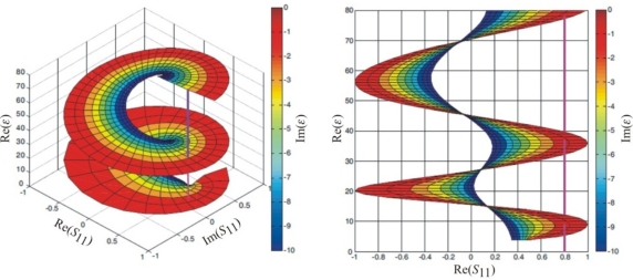
If condition (14) is met for the whole range of ZL values, multiple solutions can be obtained for ε. Inserting ZL as Zp into Equation (2) it is possible to visualize, with the help of the Matlab R2008b program [16], the relation of the complex function ε = f(S11), which is presented in Figure 7. The assumed values of x = 10 cm, f = 500 MHz. For a line perpendicular to the S11 plane the values of ε are ambiguous. Therefore the numerical solution is enhanced using a tracing procedure that first calculated ε at low frequencies, for which Equation (14) assures a single solution. Increasing measurement frequency results in meeting conditions for two or more solutions. To distinguish these solutions the procedure utilizes the former one to apply new limits of the function variability. Such approach enables to interpret the measurements in high frequencies where the wavelength of the measurement signal is shorter than the double length of the sensor rods. The detailed description of applied algorithm and calculation software is presented in [18].
Figure 7.
Four-dimension S11/ε chart (complex values) based on the model of lossy impedance transformer (left) and its view in the Re(ε)/Re(S11) plane (right).
The calibration of the TT sensor model needs the application of at least three calibration points, for example: (i) impedance of the shorted sensor at the place where the rods are connected with the epoxy resin enclosure (Z = 0 + j0), (ii) impedance of the sensor in air (Z = 1 + j0), (iii) impedance of the sensor fully inserted in acetone (or other calibration liquid from the Table 2) calculated from the Debye model. The calibration details are described in [18].
3. Materials and Methods
The porous media used for testing the sensors consisted four mineral soils taken from 10–20 cm layer below the ground surface that were characterized by parameters presented in Table 1. The soil data were taken from the data bank of Polish soils [19].
The soils were especially selected to minimize all the factors other than water content and salinity that influence the value of dielectric permittivity, i.e., non swelling or shrinking soils or those with no organic content. There were 10 soil samples with different water content, evenly spaced covering the range from air dry to saturation, for each soil 569, 610 and 622 (Table 1). The water holding capacity was calculated by dividing the weight of the water held in saturated sample by the sample dry weight. Homogeneity of water content in the samples was achieved by sealing the samples and maintaining them at 45 °C during three days.
Because of non-homogeneity of porous materials, especially soil, the liquids of known dielectric parameters (distilled water, acetone, methanol, isopropanol) described by Debye model [20] given by Equation (15) were used to assess the accuracy of the applied FDR probe models (Table 2).
| (15) |
where ε∞ and εs are the values of dielectric permittivity above relaxation frequency and in static electric field, respectively, τ is the relaxation time of the dielectric medium.
The influence of salinity on the complex dielectric permittivity was tested on 5 series (each with 10 samples) of the black soil 529. The samples were moistened with KCl solutions with variable electrical conductivity values 0, 5, 10, 15 and 20 dSm−1. Similarly to the soils 569, 610, 622, the water content in the samples were evenly distributed in steps of 0.1 of the maximum soil water capacity value.
Measurement signal generation as well as detection of the reflected one from the sensor is done by a vector network analyzer (VNA) type ZVCE from Rohde and Schwarz [21] working in the reflection mode in the frequency range 20 kHz – 8 GHz. It measured a complex reflection coefficient S11 when the sensor rods were fully inserted into the tested material. The ambient temperature in was 20.6 ± 1 °C. According to the instructions, before each series of measurement the VNA was warmed for at least one hour.
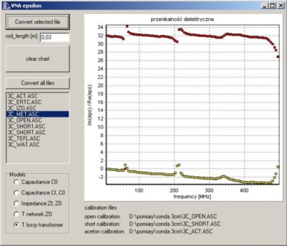
The raw data S11 from calibration measurements, as well as final measurements in the tested materials, were processed by a custom software application written in C++ Builder, where the final frequency spectrum of the complex dielectric permittivity was calculated and presented in graphic form. for each of the discussed model. Figure 8 presents the case with selected TT model. Real and imaginary parts of the complex dielectric permittivity are shown at the upper and the lower part of the diagram, respectively. More details of the application program are available in [18].
Figure 8.
Program window for processing the raw S11data measured by VNA and applied to the models: C0 (Figure 3), Cf – C0 (Figure 2), four-pole T (Figure 4), Zf – Z0 (Figure 5) and TT (Figure 6), which are selected by the user.
Evaluation of the sensor models used to determine the complex dielectric permittivity of tested media were performed by calibration of the sensors in reference liquids (Table 2), measurements by VNA in methanol and verification the calculated real and imaginary parts of the complex dielectric permittivity spectrum with the one calculated with the use of Debye model. The influence of the measurement frequency on the measured refractive index were analyzed for data collected on soil 529 samples using the sensor of 3 cm rods length.
3. Results and Discussion
3.1. Model Selection
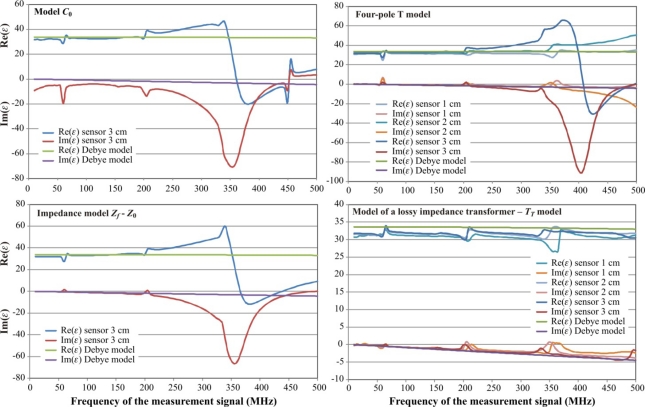
The comparison of the complex dielectric permittivity values calculated on the base of calibration measurements in reference liquids for various models described in earlier sections is presented in Figure 9.
Figure 9.
Performance comparison of the analyzed FDR sensor models for methanol as the verification medium.
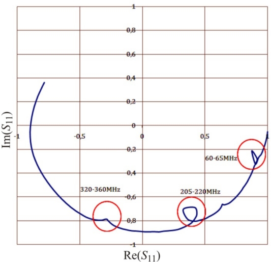
The artifacts on each graph (Figure 9), as well as in the respective graph of the complex reflection coefficient S11 measured by VNA observed for the same frequencies (Figure 10), are discussed in [22] for open-ended coax sensors. They are caused by resonance effects in an open transmission line. This happens when the length of a cable with a sensor equals to the odd multiple wavelength of the measurement signal. This was confirmed in separate tests not presented in the current study. These effects resulted in limiting the frequency range of the measurement signal to 10–500 MHz.
Figure 10.
Resonance effects (in circles) on the S11 parameter measured by VNA.
It is evident from Figure 9 that the model C0 can be successfully used only for the correct determination of the real value of the complex dielectric permittivity Re(ε) for the frequencies up to 200 MHz. The imaginary part Im(ε) has the measurement error above 10% for all applied frequencies. Similar results were found for the model Cf – C0 (Figure 2), which was not presented in Figure 9. This can be explained by a minimal influence of the Cf capacitance in the two-wire sensor.
Better results were found for the impedance model Zf – Z0, especially for the imaginary part Im(ε). However the useful frequency did not increase above 200 MHz. The graphs in Figure 9 concerning the models C0 and Zf – Z0 only refer to the sensor length equal to 3 cm, because similar results were observed for other sensor length 1 cm and 2 cm.
The four-pole T model performs better for both components of the dielectric permittivity, but for a 3 cm length probe the upper measurement frequency limit is still around 200 MHz and 350 MHz for the 2 cm length sensor. This model correctly follows the values of Debye model calculated for methanol as the reference liquid for the sensor of 1 cm rod length.
The best performance was observed for the model of lossy impedance transformer (TT model). The real part of the dielectric permittivity is not dependent on the sensor length for the whole frequency range of the measurement signal. Only a slight decrease of results are observed, especially for the real part. This effect can be explained by the probable increase of dielectric permittivity of acetone used for the sensor calibration. The sensor length affects the performance of the imaginary part of the model and the length is shorter, the measurement error of Im(ε) is bigger.
The combination of calibration points of the TT model also influenced the measurement error of ε for both components of the dielectric permittivity. The best results were obtained for the combination of water, air and acetone, where for √Re(ε) < 2 the measurement error of the real part of dielectric permittivity is less than 4% and it is below 2.2% for √Re(ε) ≥ 2.
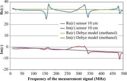
The TT model was applied to the sensor of 10 cm length of parallel metal rods and its performance is presented in Figure 11. In the frequency range 125–375 MHz the real part of dielectric permittivity of methanol has a big maximal measurement error reaching 20% of the measured value, but its average value is very close to the model value. The imaginary part of ε behaves similarly. The erroneous effect can be explained with the resonance of the open line described earlier in Figure 10 and they increase with the increase of the sensor rods’ length. It seems that the TT model could be applied for 10 cm length sensors which have bigger measurement volume as compared with 1–3 cm long ones. However before that it is necessary to eliminate the resonance effect and develop a new calibration methodology of these sensors.
Figure 11.
Performance of TT model for the FDR sensor with 10 cm length of rods.
3.2. Influence of Measurement Frequency on the Measured Refractive Index
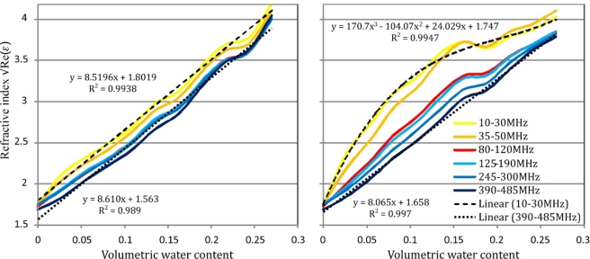
Analysis of the measurement frequency influence on the measurement result was done by the comparison of the mean values of the refractive index for six selected frequency bands. The refractive index defined as the square root of the real part of the dielectric permittivity was calculated from the TT model of a lossy impedance transformer. The selected frequency bands were: 10–30, 35–50, 80–120, 125–190, 245–300, 390–485 MHz. These bands were not burdened with errors caused by the open transmission line resonance described in the previous section.
Figure 12 presents the relation between the soil refractive index √Re(ε) and volumetric water content for the soil 529 for various frequency ranges.
Figure 12.
The influence of the measured frequency range on the value of the soil refractive index for the samples of soil 529 wetted with distilled water (left-hand graph) and 20 dSm−1 KCL solution (right-hand graph).
For soil samples wetted with distilled water the refractive index increases with the frequency decrease for the whole range of soil moisture and the trend lines representing various frequency ranges are nearly in parallel (Figure 12—left). Trend lines for all frequency ranges have the determination coefficient R2 not less than 0.989. For figure clarity, only extreme trend lines are presented.
For soil samples wetted with KCl solution of the electrical conductivity equal to 20 dSm−1, the lower the measurement frequency, the bigger was the refractive index of soil samples with the same thermogravimetric water content. In the frequency range 390–485 MHz the relation can be described by a linear relation with determination coefficient equal to 0.997. For the frequency range 10–30 MHz this relation is extremely far from linear and must be fitted with the polynomial of the 3rd degree to achieve R2 = 0.994. This means that for the tested salted sandy soil low frequency dielectric measurements of soil moisture require soil specific calibrations. However, it should be noted that the shape of this calibration still depends on the salinity level.
3.3. FDR Soil Moisture Calibration
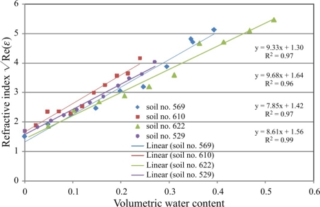
The analysis included data for the FDR sensor with 3 cm rod length and 390–485 MHz frequency range of the measurement signal, for which the real part of dielectric permittivity does not show any frequency dependence. Data for 20 measurement points of Re(ε) from this range were averaged for each soil sample to calculate the square root as the refractive index. The standard deviation for all measurements did not exceed 0.16 of the absolute value. The correlation of final data with the corresponding thermogravimetric data is presented in
The fitted linear functions are presented for comparison with literature data. The trend line fitted to the all data points is: , where a0 = 8.86, a1 = 1.48.
The values of the a0 and a1 coefficients determined for the Malicki model from the TDR calibration measurements are very close to the ones from the presented FDR calibration. This is especially true for density corrected calibration. This means that in the measurement frequency range of 390–480 MHz the soil moisture values determined for presented FDR sensor and the applied sensor model are comparable with the TDR ones.
4. Conclusions
The presented two-wire FDR sensors and the measurement methodology of the frequency spectrum of the complex dielectric permittivity enable simultaneous and selective determination of soil moisture for various frequency ranges of the measurement signal. The developed lossy impedance transformer—TT model of the FDR two-wire sensor can be used to measure the frequency spectrum of soil complex dielectric permittivity in the range 10–500 MHz, that up till now is not used in commercial FDR meters of soil moisture and salinity. It was found that for the FDR measured soil samples the real values of the complex dielectric permittivity determined for low frequencies (10–50 MHz) are higher in relation to the ones determined for high frequencies (300–500 MHz), especially for saline soils. The soil moisture values determined for the chosen mineral soil samples by the applied FDR method and sensors are comparable to the ones determined by the TDR method.
Figure 13.
FDR soil moisture calibration for the measurement frequency range 390–480 MHz.
Table 3.
Comparison of FDR calibrations of the analysed sensors with Malicki TDR calibrations [23].
| FDR measurements (Figure 13) | Malicki model | Malicki model (correction on soil density) | |
|---|---|---|---|
| a0 | 8.86 | 7.16 | 8.96 |
| a1 | 1.48 | 1.44 | 1.44 |
References
- 1.Robinson D.A., Jones S.B., Wraith J.M., Or D., Friedman S.P. A review of advances in dielectric and electrical conductivity measurement in soils using time domain reflectometry. Vadose Zone J. 2003;2:444–475. [Google Scholar]
- 2.Walker J.P., Willgoose G.R., Kalma J.D. In situ measurement of soil moisture: a comparison of techniques. J. Hydrol. 2004;293:85–99. [Google Scholar]
- 3.Jones S.B., Blonquist J.M., Robinson D.A., Rasmussen V.P., Or D. Standardizing characterization of electromagnetic water content. Vadose Zone J. 2005;4:1048–1058. [Google Scholar]
- 4.Robinson D.A., Campbell C.S., Hopmans J.W., Hombuckle B.K., Jones S.B., Knight R., Ogden F., Selker J., Wendroth O. Soil moisture measurement for ecological and hydrological watershed-scale observatories: a review. Vadose Zone J. 2008;7:358–389. [Google Scholar]
- 5.Topp G.C., Davis J.L., Annan A.P. Electromagnetic determination of soil water content: measurements in coaxial transmission lines. Water Resour. Res. 1980;16:574–582. [Google Scholar]
- 6.Logsdon S., Laird D. Cation and water content effects on dipole rotation. Soil Sci. Soc. Am. J. 2004;68:1586–1591. [Google Scholar]
- 7.Kelleners T.J., Robinson D.A., Shouse P.J., Ayars J.E., Skaggs T.H. Frequency dependence of the complex permittivity and its impact on dielectric sensor calibration in soils. Soil Sci. Soc. Am. J. 2005;69:67–76. [Google Scholar]
- 8.Chen Y.P., Or D. Geometrical factors and interfacial processes affecting complex dielectric permittivity of partially saturated porous media. Water Resour. Res. 2006;42:W06423. [Google Scholar]
- 9.Skierucha W., Malicki M.A. TDR Method for the Measurement of Water Content and Salinity in Porous Media. Institute of Agrophysics PAS; Lublin, Poland: 2004. pp. 1–152. [Google Scholar]
- 10.Skierucha W., Walczak R.T., Wilczek A. Comparison of open-ended coax and TDR sensors for the measurement of soil dielectric permittivity in microwave frequencies. Int. Agrophys. 2004;18:355–362. [Google Scholar]
- 11.Stuchly M.A., Stuchly M.M. Coaxial line reflection methods for measuring dielectric properties of biological substances at radio and microwave frequencies—a review. IEEE Trans. Instr. Measur. 1980;IM-29:176–182. [Google Scholar]
- 12.Agilent 85070E Dielectric Probe Kit 200 MHz to 50 GHz. Technical Overview. Agilent Technologies; Santa Clara, CA, USA: 2008. [Google Scholar]
- 13.Athey T.W., Stuchly M.M., Stuchly S.S. Measurement of radio frequency permittivity of biological tissues with an open-ended coaxial line: Part I. IEEE Trans. Microwave Theory Techn. 1982;30:82–86. [Google Scholar]
- 14.Wei Y.Z., Sridhar S. Technique for measuring the frequency dependent complex dielectric constants of liquids up to 20 GHz. Rev. Sci. Instrum. 1989;60:3041–3046. [Google Scholar]
- 15.Magnusson P.C., Alexander G.C., Tripathi V.K., Weisshaar A. Transmission Lines and Wave Propagation. CRC Press LLC; Boca Raton, FL, USA: 2001. [Google Scholar]
- 16.Knight A. Basics of Matlab and Beyond. Chapman & Hall/CRC Press, Inc; Boca Raton, FL, USA: 2000. [Google Scholar]
- 17.Chen L.F., Ong C.K., Neo C.P., Varadan V.V., Varadan V.K. Microwave Electronics Measurement and Materials Characterization. John Wiley & Sons Ltd; Chichester, UK: 2004. pp. 1–552. [Google Scholar]
- 18.Wilczek A. Institute of Agrophysics PAS in Lublin; Lublin, Poland: 2009. Influence of moisture and salinity of soil on its dielectric permittivity determined by frequency domain reflectometry. Ph.D. thesis (in Polish), [Google Scholar]
- 19.Glinski J., Ostrowski J., Stepniewska Z., Stepniewski W. Bank of soil samples representing mineral soils in Poland (in Polish) Probl. Agrofiz. 1991;66:1–57. [Google Scholar]
- 20.Buckley F., Maryott A.A. Table of Dielectric Dispersion Data for Pure Liquids and Dilute Solutions. Bureau of Standards Circular; Washington, DC, USA: 1958. pp. 1–101. [Google Scholar]
- 21.Operating Manual, Vector Network Analyzer ZVR/ZVRE/ZVRL. Rohde & Schwarz; Munich, Germany: 2001. [Google Scholar]
- 22.Sheen N.I., Woodhead I.M. An open-ended coaxial probe for broad-band permittivity measurement of agricultural products. J. Agric. Engineer. Res. 1999;74:193–202. [Google Scholar]
- 23.Malicki M. A., Plagge R., Roth C.H. Reduction of soil matrix effect on TDR di-electric moisture determination by accounting for bulk density or porosity. Eur. J. Soil Sci. 1996;47:357–366. [Google Scholar]


