Abstract
A serious drawback of veneering porcelains is a pronounced susceptibility to chipping. Glass-infiltrated dense zirconia structures can now be produced with esthetic quality, making them an attractive alternative. In this study, we examined the hypothesis that such infiltrated structures are much more chip-resistant than conventional porcelains, and at least as chip-resistant as non-infiltrated zirconia. A sharp indenter was used to produce chips in flat and anatomically correct glass-infiltrated zirconia crown materials, and critical loads were measured as a function of distance from the specimen edge (flat) or side wall (crown). Control data were obtained on zirconia specimens without infiltration and on crowns veneered with porcelains. The results confirmed that the resistance to chipping in graded zirconia is more than 4 times higher than that of porcelain-veneered zirconia and is at least as high as that of non-veneered zirconia.
Keywords: edge chipping, dental crowns, graded ceramics, zirconia, indentation, fracture toughness
Introduction
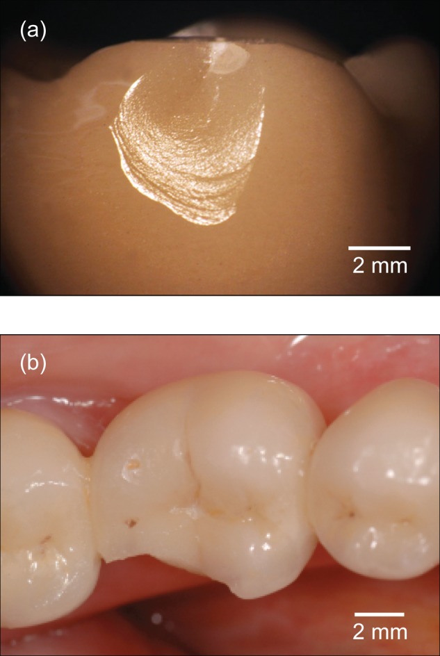
Yttria tetragonal zirconia polycrystal (Y-TZP), the strongest and toughest of the dental ceramics, is now widely used as a core material in full-coverage crowns and fixed dental prostheses (FDPs) (Sailer et al., 2007, 2009; Denry and Kelly, 2008; Swain, 2009; Al-Amleh et al., 2010). But conventional Y-TZP is not esthetic, so it is usually necessary to veneer the core with a matching porcelain. This introduces a weak link: Porcelain is brittle, with fracture resistance similar to that of tooth enamel (Chai et al., 2011). Porcelain veneers are particularly prone to chipping (Sailer et al., 2007, 2009), exacerbated by any residual stresses from thermal processing (Swain, 2009; Mainjot et al., 2011a,b; Tholey et al., 2011). Large chipping cracks in porcelain-veneered crowns may delaminate at the veneer/core interface but generally do not enter the core itself. Examples of such chipping in crowns and FDPs are shown in Fig. 1.
Figure 1.

Chipping fractures in porcelain-veneered dental prostheses: (a) full-coverage dental crown, fractured ex vivo; and (b) fixed partial denture, fractured in vivo. Photograph in (b) courtesy of Irena Sailer.
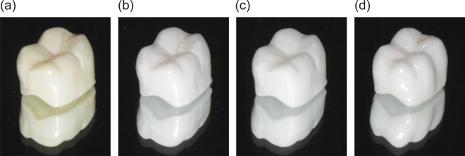
Recently, we have developed graded ceramics with high mechanical strength by infiltrating dense zirconia (or alumina) with matching glass compositions (Zhang and Kim, 2009; Zhang et al., 2010; Ren et al., 2011b). The infiltration depths are typically on the order of 0.1 mm, providing a thin but resilient veneering coat. While the translucency of the infiltrated products is not as high as that for dental porcelains, their esthetics are improved relative to those of conventional core materials, making them attractive candidates for posterior replacements. Moreover, infiltrated ceramics can be color-shaded, by judicious control of the glass composition. Infiltrated zirconias can now be produced in anatomically correct shapes and sizes. Examples of glass-infiltrated zirconia crowns in two different color shadings produced in our laboratories, along with conventional porcelain-veneered and monolithic zirconia crowns for comparison, are shown in Fig. 2.
Figure 2.

All-ceramic crowns: (a,b) graded monolithic GZG, with two tint variations to illustrate color-matching capacity; (c) monolithic zirconia; and (d) porcelain-veneered zirconia.
In this study, chipping tests were conducted on graded zirconia crowns with anatomically correct geometries. We used a simple test procedure, consisting of a sharp indenter to generate chips near the crown side walls. For quantification of the fracture resistance of such structures, critical forces required to produce the chips were measured as a function of distance from the side wall. Control tests were run on non-infiltrated zirconia specimens and on zirconia specimens with porcelain veneers. Comparative tests were run on flat specimens with orthogonal side walls to validate the test procedure.
Materials & Methods
Specimen Preparation
Preparation of the basic glass-infiltrated Y-TZP material was conducted as described in earlier papers (Zhang and Kim, 2009; Zhang et al., 2010). Zirconia specimens were pressureless-sintered from a commercial powder (TZ-3Y-E grade, Tosoh, Tokyo, Japan). Square plates of 15-mm side length were sliced from one set of blocks and then ground with 400-mesh silicon carbide abrasive paper to 2-mm thickness, with orthogonal side walls. Some of these plates were set aside for control testing. These were densified by heat treatment at 1,450°C for 2 hrs in air. The remaining plates were first pre-heated to 1,350°C for 1 hr in air, then cooled and coated with a slurry of CTE-matching silicate glass powder (65.5% SiO2, 11.7% Al2O3, 10.0% K2O, 7.3% Na2O, 3.0% CaO). The coefficient of thermal expansion (CTE) for both zirconia and glass was (10.4 ± 0.1) × 10−6 °C−1 (between 25 and 450°C) (Zhang and Kim, 2009). The coated plates were then reheated to 1,450°C for 2 hrs in air. This resulted in glass/zirconia/glass (GZG) layer structures with infiltration depths d ~ 120 µm and an average grain size 0.4 µm in the zirconia core. The surfaces of all plates were given a final polish with 0.5-µm diamond paste.
Anatomically correct crowns were CAD-CAM-machined with a LAVA CNC 500 milling system from pre-sintered LAVA zirconia blocks (3M ESPE Dental Products, Seefeld, Germany) in the shape of a standard model dental crown with average thickness 1.5 mm. Again, some of these were densified by heat treatment at 1,450oC for 2 hrs in air, and were set aside for control testing. The remaining crowns were pre-heated (1,350oC for 1 hr) and glass-infiltrated (1,450oC for 2 hrs) in the same manner as for the plates. The surfaces of all crown specimens were left in their as-prepared, unpolished state.
Another set of control crown specimens was fabricated from Vita Y-TZP blocks (In-Ceram Zirconia YZ-14 Cube, Vita Zahnfabrik, Bad Sackingen, Germany). This set was prepared to an average thickness of 0.5 mm, and the specimens were then hand-veneered with a matching porcelain (Vita VM9, Vita Zahnfabrik, Bad Sackingen, Germany) of 1 mm thickness, i.e., again with a net average thickness of 1.5 mm.
Flat specimens were glued onto a flat polycarbonate block by means of epoxy resin. In the case of the crown models, replicas of the tooth dentin onto which the crowns were to be affixed were fabricated from the crown model. Impressions (polyvinylsiloxane Aquasil, Dentsply) of the model were filled with layers of resin-based composite (Z100, 3M ESPE, St. Paul, MN, USA) with Young’s modulus 16-18 GPa (i.e., similar to that of dentin) and cured. The replicas were stored in distilled water at 37oC for 30 days to ensure hydration and to minimize any effects of water uptake on dimensional expansion after crown cementation. The crowns were cemented (Multilink Automix, Ivoclar Vivadent AG, Schaan, Liechtenstein) onto the tooth replica, with a maximum luting thickness of 100 µm. The crown-tooth assembly was embedded in acrylic resin (Orthoresin, Degudent, Germany) in a 25-mm-diameter PVC tube, with the crown buccal margin 2 mm above the surface of the resin.
To quantify the esthetics of the experimental materials, we used a commercial colorization protocol on our test materials. Specimens were machined into disks (0.45 mm thickness) and fine-polished (0.5 µm finish). Translucency was measured with a CIELAB color space spectrophotometer (SpectroShade micro, MHT S.P.A., Via Milano 12, 37020 Arbizzano di Negrar [VR], Italy) with a CIE illuminant D65 light source. Translucency parameters were calculated from color differences over white and black backgrounds (Johnston et al., 1995). In this test, a high TP value indicated greater translucency (Ahn and Lee, 2008).
Chipping Tests
Chipping tests were made with a Vickers diamond pyramid indenter loaded vertically at preselected distances h from the side wall (see insets in Figs. 3 and 4) (Chai et al., 2011). For the flat specimens, the indentations were placed on the orthogonal side walls, with the load axis parallel to the G-Z interface (Fig. 3) and the indent diagonals parallel and perpendicular to the specimen edge. For the anatomically correct specimens, the indentations were placed on the top surface, adjacent to the side of the cusps (Fig. 4, right inset). This was practical only for large values of indenter location h. For h < 300 µm, the indenter tended to slide off the rounded cusp contours, in which case the crown was sawn vertically through the center and the indentations placed adjacent to the sectioned surface of the half-specimen (Fig. 4, left inset). In this study, we were not as concerned with the absolute as with the relative chipping resistance of GZG, Y-TZP, and porcelain veneers, so such variants in test configuration should not detract from the clinical significance of the data.
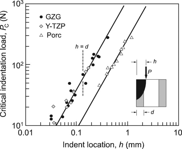
Figure 3.

Critical loads PC to produce chips as a function of distance h from the specimen edge, for flat specimens. Data for GZG (n = 17) and Y-TZP (n = 9) are from current tests; data for monolithic porcelain (n = 11) are from a previous study (Chai and Lawn, 2007a). Solid lines are best fits in accordance with the Eqn. Inset shows orientation of specimens relative to load axis. Vertical dashed line indicates thickness d of the diffusion layer in GZG specimens.
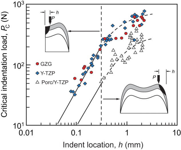
Figure 4.

Critical loads PC to produce chips as a function of distance h from the specimen edge, for anatomically correct crown specimens. Data for GZG (n = 17), Y-TZP (n = 32), and porcelain-veneered Y-TZP (n = 32). Solid lines are from Fig. 3 for flat specimens; dashed curves are simple extensions through the data. Dashed line at h ≈ 300 µm delineates between tests on section edges (left inset) and rounded crown surfaces (right inset), for all material combinations. Grayed area indicates graded layer (GZG) or porcelain veneer (Porc/Y-TZP). These grayed areas are not meant to be to scale, since the thickness of the GZG layer is much smaller (120 µm) than that of veneering porcelain (1 mm).
All specimens were mounted in a mechanical testing machine for indentation testing. A video camera was used to record the evolution of fracture from the Vickers indenter. The indenter was loaded at 0.1 mm/min until a chip abruptly spalled off a side wall. The corresponding critical loads PC were recorded as a function of chip distance h for each specimen set.
Results
Translucency tests indicated the following TP values (n = 6 measurement/specimen): Vita porcelain, 41.45 ± 0.38; GZG, 13.58 ± 0.13; and monolithic Y-TZP, 9.73 ± 0.12. t tests indicated significant differences between any pair of materials (p < 0.05). Thus, the GZG can be considered esthetically superior relative to Y-TZP, if well below the level of conventional porcelain.
The results of chipping tests on flat Y-TZP and GZG specimens are plotted logarithmically in Fig. 3 as critical chipping load PC vs. distance h. Each data-point represents a separate test. The solid lines are best fits to the chipping relation (Chai and Lawn, 2007a; Chai et al., 2011),
where T is toughness (resistance to crack propagation) and β is a dimensionless coefficient. The Y-TZP and GZG data overlap, indicating indistinguishable values of toughness for these materials—hence a common fitted line through these two sets of data. A Student’s t test was conducted on the values of the quantity PC/h3/2 calculated from the P–h data for each material: Differences in this quantity were found to be insignificant (p < 0.05). For the GZG specimens, recall that the infiltration layer extends only to depth d = 120 µm beneath the outer surfaces, so that some of the chips will have actually initiated within the interior zirconia layer en route through the graded layer to the side wall. Nevertheless, analysis of the GZG critical load data showed no apparent discontinuity with indent location h on either side of the glass infiltration depth d in Fig. 3.
Also shown in Fig. 3 are data and best-fit solid lines for monolithic veneering porcelain, from an earlier publication (Chai and Lawn, 2007a). The critical loads PC for this material lie about a factor of 4 lower than those for Y-TZP and GZG at any given h. This factor of 4 is consistent with the relative toughness values for porcelain- and zirconia-based ceramics (Chai and Lawn, 2007a). A t test on the zirconia and porcelain datasets confirmed a significant difference in these two material classes (p > 0.05).
Analogous data for the chipping tests on anatomically correct specimens are shown in Fig. 4. The insets show how the indentations were placed, relative to the flat sectioned surface at small h (left) and the rounded side wall at large h (right). The solid lines at small h are best fits to the flat-specimen datasets taken directly from Fig. 3. The dashed curves are extensions of these fitted lines through the data at large h. The fact that the data at large h deviate from the linear representations and show somewhat greater scatter suggests that rounded crown geometry is a factor in the critical conditions for large-scale chipping. Nevertheless, analysis of the Y-TZP and GZG data again showed few discernible mutual differences. In contrast, the dataset for porcelain-veneered Y-TZP once more lay about a factor of 4 lower on the PC axis relative to Y-TZP and GZG.
In all cases, the depth of the chip on the specimen side walls below the indentation surface lay in the range 3 to 5 times the contact-to-wall distance h, commensurate with chip sizes reported in earlier studies (Chai and Lawn, 2007a; Chai et al., 2011). The largest chips extended all the way down the crown side walls. It may be reiterated that, in the GZG specimens in Figs. 3 and 4, the chips generally penetrated the relatively thin (120 µm) graded layer into the zirconia substrate. Since the GZG material has toughness similar to that of the zirconia, the crack propagation was not perceptibly affected by intersecting the interface (Zhang et al., 2010). In the veneered Y-TZP specimens in Fig. 4, the chips were contained within the relatively thick (1 mm) porcelain, except at higher values of h, where the cracks deviated onto the substrate interface before spalling off the side walls. This latter irregularity in crack trajectory could account for the higher scatter in veneered Y-TZP data at large h in Fig. 4.
Discussion
Our study demonstrates enhancement in properties of zirconia-based ceramics by infiltration of glass compositions into the exposed surfaces. We have indicated previously that such infiltration can improve strength, wear, and fatigue resistance of zirconia ceramics by diminishing both flexure- and contact-induced tensile stresses at the outer surface of the diffusion layer (Kim et al., 2007, 2010b; Zhang and Kim, 2009; Zhang and Ma, 2009; Zhang et al., 2010; Ren et al., 2011a,b). The present results on GZG show that the resistance to chipping fracture is much higher than that for porcelain-veneered zirconia structures, by at least a factor of 4, and is at least as high as that for the non-graded Y-TZP. In a broader context, our study demonstrates that the mechanical performance of graded all-ceramic crown structures may be assessed simply, efficiently, and accurately by systematic chip-testing on small test specimens.
Chip formation near the edges of brittle structures occurs by initial stable growth of a so-called ‘median’ crack beneath the sharp contact, followed by unstable acceleration of the crack toward the side wall in the final stages (Chai and Lawn, 2007a). In veneered structures, this propagation is easier because of the relatively low toughness of the porcelain (Chai et al., 2011). Moreover, the toughness of the interface between the bonded porcelain and its zirconia core is invariably lower even than that of the porcelain itself (Kim et al., 2006; Guess et al., 2008). For large contact-to-edge distances, the median crack is likely to intersect this weak interface, causing premature delamination. This issue is circumvented in GZG structures because of the stronger bonding between the graded GZG layer and underlying zirconia substrate. In this latter case, any analogous cracks intersecting the GZG interface will penetrate the zirconia sublayer without delamination, thus resulting in much improved resistance to chipping.
Some other issues warrant comment: (1) Thermally induced stresses in porcelain veneers can exacerbate chipping in crowns and FDPs, even in well-matched substrate systems (Swain, 2009; Mainjot et al., 2011a,b; Tholey et al., 2011). CTE mismatch and low thermal conductivity of a zirconia framework are less likely to manifest themselves in GZG, because the chemical interface between the overlayer and the substrate is less abrupt (Zhang et al., 2010). In support of this contention is the overlap between GZG and Y-TZP data in Fig. 4. (2) Infiltration of Y-TZP improves chemical durability by stabilizing against thermal and chemical degradation (Chevalier et al., 1999; Chevalier, 2006; Zhang and Kim, 2009; Kim et al., 2010a). (3) It is well-documented that configurational complexities and inclined loadings can have a significant effect on critical conditions for chipping (Chai and Lawn, 2007b). Given our primary concern here with an inter-comparison of material systems, our use of simple, common specimen geometries is well-suited to relative evaluations with minimal complexity. (4) The presence of glass in the graded layer offers some improvement in the esthetics of the zirconia structure, with potential for color matching to the surrounding dentition by controlling the glass composition. Although the esthetics are not as good as for veneering porcelain, they are superior to those of pure zirconia, suggesting that GZG crowns and bridges might serve usefully as at least posterior prostheses.
Footnotes
Funding was provided by the United States National Institute of Dental and Craniofacial Research (Grant R01 DE017925), the National Science Foundation (Grant CMMI-0758530), the Israeli Science Foundation (Grant ISF-0605414391), and NIST (via Dakota Consulting Inc.).
No conflicts of interest were reported for this article. Information of product names and suppliers in this paper is not intended to imply endorsement by NIST.
References
- Ahn JS, Lee YK. (2008). Difference in the translucency of all-ceramics by the illuminant. Dent Mater 24:1539-1544 [DOI] [PubMed] [Google Scholar]
- Al-Amleh B, Lyons K, Swain MV. (2010). Clinical trials in zirconia: a systematic review. J Oral Rehabil 37:641-652 [DOI] [PubMed] [Google Scholar]
- Chai H, Lawn BR. (2007a). A universal relation for edge chipping from sharp contacts in brittle materials: a simple means of toughness evaluation. Acta Mater 55:2555-2561 [Google Scholar]
- Chai H, Lawn BR. (2007b). Edge chipping in brittle materials: effect of side-wall inclination and loading angle. Int J Fract 145:159-165 [Google Scholar]
- Chai H, Lee JJ, Lawn BR. (2011). On the chipping and splitting of teeth. J Mech Behav Biomed Mat 4:315-321 [DOI] [PubMed] [Google Scholar]
- Chevalier J. (2006). What future for zirconia as a biomaterial. Biomaterials 27:535-543 [DOI] [PubMed] [Google Scholar]
- Chevalier J, Cales B, Drouin JM. (1999). Low-temperature aging of Y-TZP ceramics. J Am Ceram Soc 82:2150-2154 [Google Scholar]
- Denry I, Kelly JR. (2008). State of the art of zirconia for dental applications. Dent Mater 24:299-307 [DOI] [PubMed] [Google Scholar]
- Guess PC, Kulis A, Witkowski S, Wolkewitz M, Zhang Y, Strub JR. (2008). Shear bond strengths between different zirconia cores and veneering ceramics and their susceptibility to thermocycling. Dent Mater 24:1556-1567 [DOI] [PubMed] [Google Scholar]
- Johnston WM, Ma T, Kienle BH. (1995). Translucency parameter of colorants for maxillofacial prostheses. Int J Prosthodont 8:79-86 [PubMed] [Google Scholar]
- Kim JW, Bhowmick S, Hermann I, Lawn BR. (2006). Transverse fracture of brittle layers: relevance to failure of all-ceramic dental crowns. J Biomed Mater Res 79:58-65 [DOI] [PubMed] [Google Scholar]
- Kim JW, Bhowmick S, Chai H, Lawn BR. (2007). Role of substrate material in failure of crown-like layer structures. J Biomed Mater Res 81:305-311 [DOI] [PubMed] [Google Scholar]
- Kim JW, Covel NS, Guess PC, Rekow ED, Zhang Y. (2010a). Concerns of hydrothermal degradation in CAD/CAM zirconia. J Dent Res 89:91-95 [DOI] [PMC free article] [PubMed] [Google Scholar]
- Kim JW, Liu L, Zhang Y. (2010b). Improving the resistance to sliding contact damage of zirconia using elastic gradients. J Biomed Mater Res 94:347-352 [DOI] [PMC free article] [PubMed] [Google Scholar]
- Mainjot AJ, Schajer GS, Vanheusden AJ, Sadoun MJ. (2011a). Residual stress measurement in veneering ceramic by hole-drilling. Dent Mater 27:439-444 [DOI] [PubMed] [Google Scholar]
- Mainjot AJ, Schajer GS, Vanheusden AJ, Sadoun MJ. (2011b). Influence of cooling rate on residual stress profile in veneering ceramic: measurement by hole-drilling. Dent Mater 27:906-914 [DOI] [PubMed] [Google Scholar]
- Ren L, Liu L, Bhowmick S, Gerbig YB, Janal MN, Thompson VP, et al. (2011a). Improving fatigue resistance of alumina through surface grading. J Dent Res 90:1026-1030 [DOI] [PMC free article] [PubMed] [Google Scholar]
- Ren L, Janal MN, Zhang Y. (2011b). Sliding contact fatigue of graded zirconia with external esthetic glass. J Dent Res 90:1116-1121 [DOI] [PMC free article] [PubMed] [Google Scholar]
- Sailer I, Fehér A, Filser F, Gaukler LJ, Lüthy H, Hämmerle CH. (2007). Five-year clinical results of zirconia frameworks for posterior fixed partial dentures. Int J Prosthodont 20:383-388 [PubMed] [Google Scholar]
- Sailer I, Gottner J, Känel S, Hämmerle CH. (2009). Randomized controlled clinical trial of zirconia-ceramic and metal-ceramic posterior fixed dental prostheses (FDPs): a 3-year follow-up. Int J Prosthodont 22:553-560 [PubMed] [Google Scholar]
- Swain MV. (2009). Unstable cracking (chipping) of veneering porcelain on all-ceramic dental crowns and fixed partial dentures. Acta Biomater 5:1668-1677 [DOI] [PubMed] [Google Scholar]
- Tholey MJ, Swain MV, Thiel N. (2011). Thermal gradients and residual stresses in veneered Y-TZP frameworks. Dent Mater 27:1102-1110 [DOI] [PubMed] [Google Scholar]
- Zhang Y, Kim JW. (2009). Graded structures for damage resistant and aesthetic all-ceramic restorations. Dent Mater 25:781-790 [DOI] [PMC free article] [PubMed] [Google Scholar]
- Zhang Y, Ma L. (2009). Optimization of ceramic strength using elastic gradients. Acta Mater 57:2721-2729 [DOI] [PMC free article] [PubMed] [Google Scholar]
- Zhang Y, Chai H, Lawn BR. (2010). Graded structures for all-ceramic restorations. J Dent Res 89:417-421 [DOI] [PMC free article] [PubMed] [Google Scholar]


