Abstract
Tetrahedral meshes are being extensively used in finite element methods (FEM). This paper proposes an algorithm to generate feature-sensitive and high-quality tetrahedral meshes from an arbitrary surface mesh model. A top-down octree subdivision is conducted on the surface mesh and a set of tetrahedra are constructed using adaptive body-centered cubic (BCC) lattices. Special treatments are given to the tetrahedra near the surface such that the quality of the resulting tetrahedral mesh is provably guaranteed: the smallest dihedral angle is always greater than 5.71°. The meshes generated by our method are not only adaptive from the interior to the boundary, but also feature-sensitive on the surface with denser elements in high-curvature regions where geometric feature most likely reside. A variety of experimental results are presented to demonstrate the effectiveness and robustness of this algorithm.
Keywords: Tetrahedral mesh generation, Dihedral angle, Adaptivity, Feature sensitivity
1. Introduction
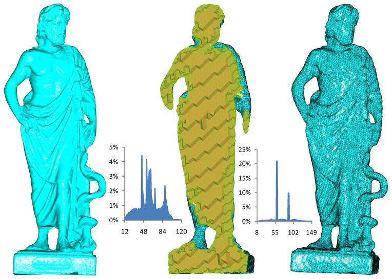
The finite element method (FEM) has been a very popular numerical approach for solving partial differential equations in many applications. There is an increasing need on quality and adaptive tetrahedral mesh generation, as the success and efficiency of FEM-based simulation relies largely on the quality and adaptivity of tetrahedral meshes being used. Typically, the accuracy and stability of the numerical solution are mainly affected by the shape of the worst tetrahedral element. The quality of a tetrahedral element is commonly measured in terms of minimum and/or maximal dihedral angles – too small and too large angles would lead to higher instability and less accuracy of the solution. Therefore, having a lower (or equivalently upper) bound of the dihedral angles in a tetrahedral mesh is important in correctly and effectively solving a linear system [1]. In addition, to reduce the computational time, the number of tetrahedral elements should be as small as possible while important geometric features should be faithfully retained. Taking these factors into account, we propose in this paper a robust and general meshing algorithm to generate feature-sensitive, adaptive, and high-quality tetrahedral meshes from an arbitrary surface mesh. Fig. 1 shows an example of tetrahedral mesh generation from a Greek sculpture surface mesh.
Figure 1.
The Greek sculpture model. Left: the original surface mesh. Middle: the cut-view of the tetrahedral mesh generated. Right: the surface view of the tetrahedral mesh generated. The left histogram is calculated with the angles of the generated boundary surface mesh, where the angle range is [12.31°, 119.54°]. The right histogram is on the dihedral angles of the tetrahedra generated, where the angle range is [8.63°, 148.29°].
In the last two decades, an extensive study on tetrahedral mesh generation has been performed [2, 8]. The related techniques can be classified by the general strategies they employ, including Delaunay-based, advancing-front-based, and octree-based methods. The Delaunay-based methods usually attempt to distribute a set of vertices in the domain, which are then triangulated by using the Delaunay triangulation [10]. During this process, additional vertices could be iteratively added if needed. This technique is very successful in 2D mesh generation, but may not work very well in generating high quality 3D tetrahedral meshes, where some nearly degenerate elements known as slivers often occur. Miller et al. [4] proposed a sphere-packing technique for Delaunay-based mesh generation, refinement and coarsening. It generates its final vertex set before triangulating it. This algorithm has provable bounds; however, it might stop early if fewer vertices are needed than the theory suggests. Borouchchaki et al. [5, 6] designed an anisotropic mesh generator to support more general mesh anisotropy throughout the domain. Chew [7] presented an algorithm to eliminate slivers by adding points in a randomized manner. This algorithm produces constant density meshes. Additionally, it does not address the slivers completely. Shewchuk[9] gave a comprehensive overview of the Delaunay-based methods and analyzed why the theoretical results could not be realized in practice. Cohen-Steiner [12] proposed an algorithm that can triangulate any polyhedral domain with Delaunay tetrahedra though without any quality guarantee. Cheng et al. [14] applied a sliver exudation technique to remove poor tetrahedra. Later, Cheng et al. [13] combined the sliver exudation method with the Delaunay refinement to give a deterministic algorithm to mesh bounded domains with tetrahedra. Similarly, Oudot et al. [15] took advantage of the sliver exudation method to improve the quality of tetrahedral meshes. The sliver exudation usually can remove most of the poor tetrahedra, however, it cannot remove all of them and the tetrahedra with dihedral angles less than 1° occasionally exist [16]. Alliez et al. [17] designed a Delaunay-based variational method to generate isotropic tetrahedral meshes, mixed with a constrained relaxation on the domain boundary. The method is shown to generate nicely-shaped tetrahedra throughout the domain, however, the slivers could survive near the domain boundary. Dardenne et al. [18] adopted the variational method to produce tetrahedral meshes from discrete data. Tournois et al. [19] proposed an effective meshing algorithm by interleaving Delaunay refinement and mesh optimization strategies. From their results, the slivers with small dihedral angles still appear around the domain boundary. In addition, Freitag et al. [20] adopted the techniques of optimization-based smoothing and topological transformations to generate quality tetrahedral meshes, but again the dihedral angles less than 1° sometimes still exist.
Advancing front-based methods start from the boundary of a domain and insert new Steiner points inside the domain so that the generated tetrahedra have acceptable shapes and sizes that conform to the desired sizing function [17, 3, 21]. With these methods, the quality of this surface triangulation has a large impact on the following three dimensional algorithm’s performance. Poorly shape surface triangles will engender ill-shaped tetrahedra. Frey et al. [3] designed a method for improving the mesh quality by imposing the Delaunay triangulation on the advancing front methods. Li et al.[22] used a variant of the advancing front method, referred to as bubble packing, to generate tetrahedra. This method produces good tetrahedron shape and size, but the computational cost increase significantly and the dihedral angles of generated tetrahedra are not discussed. Marcum et al. [23] combined the Delaunay and advancing front methods to generate tetrahedra, in which a Delaunay triangulation was constructed and used as a background mesh. New vertices were inserted using the advancing front method. The approach is fast but the quality of the generated tetrahedral mesh is not always good. Ito et al. [24] proposed a robust isotropic tetrahedral mesh generation method using advancing front strategy. At the end of the mesh generation process, the angle-based smoothing approach is adopted to improve the resulting mesh quality. As a result, the mesh quality could be enhanced to some degree. However, bad tetrahedra with small dihedral angles (e.g. 1°) still survive occasionally. In addition, all advancing front techniques encounter difficulties dealing with front-merging, which, however, may occur near the high curvature regions of the boundary [25, 26, 27].
Octree-based methods try to subdivide the domain enclosing the given mesh recursively until certain stopping criterion is reached. Yerry and Shep-hard [28] pioneered the octree-based mesh generation algorithms. Fuchs [29] and Naylor [30] proposed a meshing method based on the body-centered cubic lattice, and obtained the high quality tetrahedra. Schneiders et al. [31] presented an algorithm for hexahedral mesh generation, which starts with an octree discretization of the interior of the input object and then the isomorphism technique is exploited to adapt the mesh to the object boundary. Boyd et al. [32] proposed an automated method to generate volumetric mesh from voxel-based image data based on octree-based techniques. Ito et al. [33] developed an octree-based mesh generator to automatically create hexahedral meshes from triangulated surface meshes without any sharp geometrical features for computational structural mechanics simulations. In the paper, a set of refinement templates is given to create geometry without producing many extra elements, and a buffer layer is inserted on an octree core mesh and node smoothing is applied to improve the final mesh quality. Since the smoothing method is exploited as a post-processing step, the mesh quality could be improved, while there is no hard guarantee.
Molino et al. [27] exploited a crystalline, red-green strategy to decompose deformable objects with tetrahedra, in which an iterative optimization procedure was used to deform the tetrahedra so that they conformed to the boundary. This iterative method is non-trivial from the computational point of view. Although the dihedral angles shown in the experimental data were within [13°, 156°], no guarantee was provided.
Zhang et al. [34, 35] proposed an effective algorithm to extract adaptive and quality 3D meshes from 3D imaging data by using the dual contouring and octree-based methods. The mesh generated by their method is nonuniform on the boundary and adaptive inside. However, the dihedral angles are not guaranteed in the resulting tetrahedra especially those near the surface.
Labelle and Shewchuk [36] presented an iso-surface stuffing algorithm to generate tetrahedral meshes where the dihedral angles are bounded by [10.7°, 164.8°]. It is the first method offering guarantee on dihedral angles. However, when non-uniform tetrahedra on the surface boundary are preferred, the range of dihedral angles becomes [1.66°, 174.72°].
2. Tetrahedral Mesh Generation Algorithm
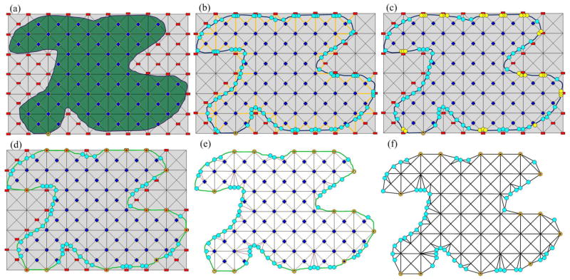
Our tetrahedral mesh generation algorithm is based on the body centered cubic (BCC) tetrahedral lattice, a common crystal structure in nature with many desirable properties [27]. The BCC lattice is constructed by adding a new node at each cell center and connecting it to the eight vertices of the cell and six neighboring cell centers. The BCC lattice is highly structured and computationally efficient, and has been utilized in various types of numerical simulation. When dealing with a bounded domain, however, the BCC lattice must be carefully remeshed near the domain boundary so that the tetrahedral mesh generated agrees with the given boundary. To this end, our method consists of the following four steps (see Fig. 2 for a two dimensional illustration):
Figure 2.
A two dimensional illustration of our tetrahedral generation algorithm. Note that the octree subdivision is adaptive in our algorithm. However, we do not show the adaptivity here for simplicity. (a) Computing the signs for each BCC grid; (b) Calculating the cutting points; (c) Detecting the “too close” cutting points; (d) Snapping the “too close” cutting points to the corresponding BCC lattice grids; (e) Decomposing the boundary polyhedra into tetrahedra; (f) Obtaining the final tetrahedral mesh.
Subdivide the octree of an input surface mesh based on Euclidean distance transformation. A few geometric properties of the input mesh are utilized to refine the subdivision adaptively from interior to boundary, and from low curvature to high curvature areas.
Compute the sign of every node in the BCC lattice. For each edge of the BCC grid, if the corresponding signs of the two endpoints are different, then calculate the cutting (intersecting) point where the edge crosses the input surface mesh.
Detect the cutting points that are “too close” to the original BCC nodes and snap them to the corresponding nodes. Equivalently, we adjust the sign of that node to zero. We refer to this process as cutting point snapping.
Decompose the boundary polyhedra into tetrahedra. For each BCC tetrahedron, if all signs of its vertices are negative (meaning ”outside”), we ignore it (we assume that only the interior tetrahedralization is of interest). If all signs are positive (meaning ”inside”), we leave it as the final tetrahedron. Otherwise, the tetrahedron is split by the input surface mesh into inside and outside parts and we further decompose the inside part (a polyhedron) into tetrahedra.
2.1. Constructing BCC Lattice
A cubic bounding box of the input surface mesh is first generated and then subdivided by using the top-down octree-based strategy. To make nonuniform tetrahedral meshes on the surface, some geometric criteria, such as the curvature and the size of triangles on the surface, are considered as well. In addition, the depth of the octree subdivision is greater as the nodes get farther away from the surface. A conforming condition is enforced so that the depth-disparity between face-adjacent octree leaf nodes is never greater than 1. As a result, we have two cases to consider:
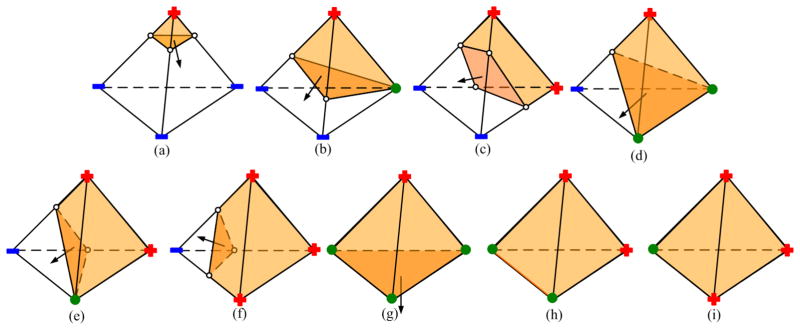
0-depth-disparity. For the common face of two adjacent leaf nodes, we consider the four edges of the face. If all four edge-adjacent leaf nodes of one edge have the same depth, we use the traditional way to construct the BBC tetrahedron; that is, using the center points of the two face-adjacent nodes and two end points of this edge to form a tetrahedron (see Fig. 3(a)). Otherwise, two BCC grids are constructed by using the middle point of the edge (see Fig. 3(b)).
1-depth-disparity. We split the common quadrilateral face of two adjacent leaf nodes into two triangular faces along its diagonal. The center point of each leaf node, together with three vertices of each split triangular face, comprises one BCC grid (see Fig. 3(c)).
Figure 3.
The BCC grid of 0-depth-disparity when four edge-adjacent leaf nodes of one edge of the common face are in (a) the same depth, and (b) the different depth. (c) BCC tetrahedra of 1-depth-disparity.
2.2. Snapping Cutting Points
After the BCC lattice is constructed, we compute the scalar value for each vertex of the tetrahedra using the Euclidean distance transformation to the input surface mesh S. Each vertex is associated with a sign: positive (inside S), negative (outside S), and zero (on S). For interior tetrahedra, where all vertices are labeled with ’+’ sign, we consider them as the final tetrahedra. Tetrahedra with all vertices labeled with ’−’ sign are removed. Then, the remaining problem is how to deal with the BCC grids crossing the surface mesh. To this end, we borrow the idea of the marching cube technique to split the boundary tetrahedra into inside and outside parts.
According to the marching cube method, if the signs of two endpoints of one edge are different, there must be an intersection point between the edge and the original surface mesh. We refer to the intersection point as a cutting point. The marching cube algorithm is able to produce smooth triangular faces but some of the resulting angles may be extremely small. Consequently, the decomposed tetrahedra containing those triangular faces would have small dihedral angles. It is observed that a triangular face with small angle occurs when two vertices of the triangle are “too close” to a BCC lattice grid while the third vertex is far away from the grid. To eliminate these triangular faces, we change to zero the scalar values of the vertices that are too close to the BCC grids, which is equivalent to snapping those vertices to the corresponding BCC grids. To measure how close is “too close”, we take the following strategy. For each cutting point, we calculate its associated lambda values to the end points of the corresponding edge. In Fig. 4, we show as an example a cutting point p on the edge v1v2. One lambda value of p to v1 is computed as ; the other lambda value to v2 is . If λ1 is less than a threshold value λ, then we set the scalar value of v1 as zero, i.e., snap p to v1. If λ2 is less than λ, we snap p to v2. Otherwise, we skip this cutting point. Although this modification (the snapping approach) can generate better dihedral angles, the price paid is that the resulting surface mesh is not as smooth as the one generated by the original algorithm. This will be addressed later.
Figure 4.
Snapping the cutting point. (a) The lambda values of cutting point. Given a threshold value λ, we can easily obtain two cut-off points A, B, and determine the un-snapping area AB (green segment) and snapping areas v1A, v2B (orange segments) in (b). If p is located in the un-snapping area, then p remains unchanged; (c), (d) otherwise, snap p to the corresponding end point of edge.
2.3. Decomposing Boundary BCC Grids
After snapping the cutting points, we get the new signs of the BCC lattice grids. The tetrahedra that are completely outside the input surface are removed and those completely inside are kept. The inner parts of the tetrahedra across the surface form various types of polyhedra, which are further decomposed into tetrahedra. Fig. 5 lists all possible cutting polyhedral stencils. In some cases there are more than one possible stencil, where the quadrilateral faces could be bisected into triangles in different ways. Taking for example the case (e) in Fig. 5, the inside polyhedron can be split into two tetrahedra with two different methods, see Fig. 6. One way is along vertex 1-2-7; the other way is along 1-3-6. As a result, two pairs of tetrahedra are generated in Fig. 6(c), (e).
Figure 5.
Cutting stencils for boundary BCC grids. Vertices of the BCC grids are labeled with their signs (+, −, 0). Cutting points are white, and inside polyhedra are yellow.
Figure 6.
Decomposing an inside polyhedron in different ways.
There are different ways to decompose a polyhedron into tetrahedra. Taking the dihedral quality of tetrahedra into consideration, we employ an optimal scheme described below. Note that ambiguous cases always occur at the quadrilateral face of the polyhedron containing two cutting points. Suppose a triangle with vertex (a, b, c) and two cutting points p1, p2 on edge ab and ac, respectively (see Fig. 7(a)). The quadrilateral face of the polyhedron is composed of vertex b, c and cutting point p1, p2. We calculate the lambda values for p1, p2. If λ1 is less than λ2, we then split the quadrilateral face along the diagonal p2b; otherwise, the face is divided along the diagonal p1c (see Fig. 7(b), (c)).
Figure 7.
Splitting the quadrilateral face of a polyhedron p1bcp2. (a) Point p1, p2 are cutting points and their lambda values are λ1, λ2, respectively. (b) When λ2 is greater than λ1, then split the face along p2b; (c) Otherwise, split the face along p1c.
In particular, the case(c) in Fig. 5 has more variations, see Fig. 8. If λ6 > λ7 and λ8 > λ5, there is an unique way to decompose the polyhedron (2 –3 –5 –6 –7 –8) into tetrahedra, according to the optimal split criterion above, i.e. (2 – 7 – 8 – 6), (2 – 8 – 5 – 6) and (3 – 7 – 8 – 2), see Fig. 8(a). However, if λ6 > λ7 and λ5 > λ8, only one tetrahedron can be decomposed accordingly, i.e. (2 – 3 – 5 – 6), and for the remaining polyhedron (2 – 3 – 6 – 7 – 8), there are two ways to decompose it: one is to connect 6 – 8, and the other is to connect 5 – 7. Here, we calculate two dihedral angles: ∠(5 – 68 – 7) and ∠(6 – 57 – 8). If ∠(5 – 68 – 7) > ∠(6 – 57 – 8), we decompose (2 – 3 – 6 – 7 – 8) along 3 – 6 – 8 (Fig. 8(b)); otherwise, along 3 – 5 – 7 (Fig. 8(c)). By this way, the case(c) in Fig. 5 can be decomposed optimally.
Figure 8.
The decomposition of the case(c) in Fig. 5. (a) λ6 > λ7 and λ8 > λ5; (b) λ6 > λ7, λ5 > λ8 and ∠(5–68–7) > ∠(6–57–8); (c) λ6 > λ7, λ5 > λ8, and ∠(5–68–7) <= ∠(6–57–8).
The combination of the snapping technique and the optimal decomposition strategy gives good dihedral angles both inside and on the surface. However, as we mentioned earlier, the snapping method results in good angles but less smooth surface. We thus utilize the normal-based surface smoothing technique [37] to reduce the bumpiness on the surface of the tetrahedral mesh. To keep the good dihedral angles already achieved, we restrict the smoothing (or vertex-moving) to where no worse dihedral angles are introduced.
3. Adaptivity and Angle Guarantees
3.1. Adaptive Tetrahedra
In finite element applications, the computational time is mainly affected by the number of tetrahedra in a mesh. By using the octree refinement strategy, the tetrahedral mesh generated is adaptive inside the domain and on the boundary of the mesh as well. As the top-down octree subdivision is used in our method, we enforce the constraint that the depth-disparity between face-adjacent leaf nodes of octree is never greater than 1. As a result, the tetrahedra get coarser and coarser from the boundary to interior of the domain.
To guarantee the adaptivity of tetrahedral meshes on the domain boundary, we consider two criteria: triangle size of the input mesh and the flatness of the surface. On one hand, we determine whether there is at least one triangular face contained in each octron during the subdivision. If there is no triangular face in the octron, then we stop subdividing this octron. On the other hand, let N = {ni|i = 0, 1, 2, …, m} be the normal vectors of all triangular faces contained in an octron, we define the flatness metric as follows:
| (1) |
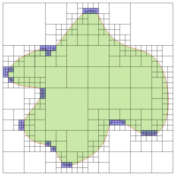
If the flatness f is greater than a pre-defined threshold, we further subdivide the octron; otherwise, stop subdividing it. Therefore, the resulting tetrahedra are denser in high curvature areas of the input mesh and sparser in low curvature areas. Fig. 9 gives a two-dimensional illustration of our octree subdivision method.
Figure 9.
A two-dimensional illustration of the adaptive octree subdivision. Note that the density of tetrahedra gets higher from interior to boundary, and from low curvature to high curvature areas of the input mesh.
3.2. Minimal Dihedral Angles
Our method offers a guarantee that all tetrahedra it generates have good dihedral angles. There are only a few cases to test from the BCC lattice, but there is an infinite number of positions where a cutting point might be located. To simplify the analysis, we take advantage of a computer-aided proof method to verify the angle bound as detailed below.
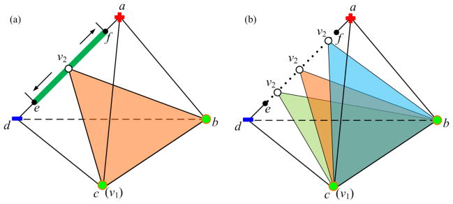
The vertex of each generated tetrahedron is located either on the vertex, or on the edge of a BCC grid. Fig. 10 gives two types of those vertices, v1, v2. v1 is fixed on the vertex of the tetrahedron abcd. Originally, v2 could be placed anywhere on the edge ad. Because the cutting-point snapping strategy is adopted, v2 is limited in the segment ef where . We sample ef into a finite number ns of points and thereby v2 could be placed on any of these sampling points. Therefore, the maximal number of cases for each tetrahedron would be , where all four vertices are located on the four edges of a BCC grid. Based on this idea, we have written a program to estimate the worse-case dihedral angles for each tetrahedron.
Figure 10.
The demonstration of computer-aided proof for minimal dihedral angle calculation.
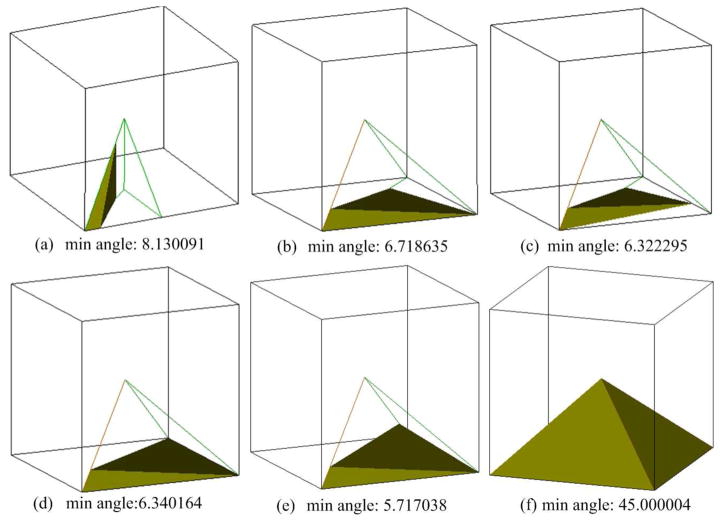
According to the snapping strategy, the worse-case dihedral angles are dependent on the value of λ. Taking the symmetry into consideration, the BCC grid tetrahedra could be simplified into three general cases (see Fig. 11). In particular, the minimum dihedral angles for specific values of λ are shown in Table 1, where we can see that the bigger the value of λ, the bigger the minimum dihedral angle. However, we should notice that a big value of λ would lead to high bumpiness of the boundary mesh due to vertex snapping. Therefore, there is a “trade-off” between the minimum dihedral angle and the smoothness of the surface boundary. Based on our experience, λ = 0.2 generally produces favorable results. with ns as 200 and λ as 0.2, we have obtained the minimal dihedral angle for each case in Fig. 5, and verified that the overall minimum dihedral angle is 5.71° (see details in Fig. 12).
Figure 11.
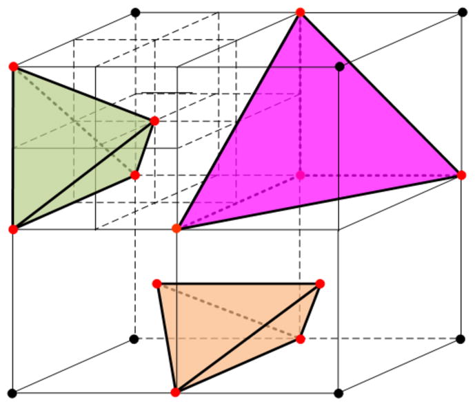
Three general cases of the BCC grid tetrahedra.
Table 1.
Minimum dihedral angles for different values of λ (in degree)
| λ | 0.1 | 0.2 | 0.3 | 0.4 | 0.5 |
|---|---|---|---|---|---|
| minimum dihedral angle | 2.862 | 5.717 | 8.565 | 11.422 | 14.312 |
Figure 12.
The minimal dihedral angle for each case in Fig. 5. The minimum dihedral angle is 5.717038° if we set ns = 200 and λ = 0.2. The corresponding relationship to the cases listed in Fig. 5 is: (a) to Fig. 5(a); (b) to Fig. 5(b); (c) to Fig. 5(c); (d) to Fig. 5(d); (e) to Fig. 5(e), (f); (f) to Fig. 5(g), (h) and (i).
4. Results and Discussion
All algorithms described have been implemented in Visual C++ and OpenGL and run on a PC with 1.8GHz CPU and 2GB RAM. A user-friendly GUI has been created encapsulating the implemented algorithms and will be made publicly available to the research community. We have tested our algorithm on a variety of 3D surface mesh models, and presented a couple of results in this section.
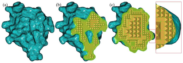
Fig. 13 gives the tetrahedral mesh generation result from a molecular surface mesh (2CMP), randomly chosen from the Protein Data Bank (http://www.rcsb.org). The original surface mesh in Fig. 13(a) is generated using the approach described in [38], and smoothed with the method in [39]. From the cut-view result, we notice that the tetrahedral mesh is adaptive from interior to boundary. The angle histogram of the original surface mesh is shown in Fig. 13(a), while Fig. 13(b), 13(c) give the angle histograms of the boundary surface mesh and the tetrahedral mesh. The majority of the tetrahedra are inside the surface mesh, and the dihedral angles for those standard tetrahedra are fixed, where the minimum one is 45°. To compare the histograms in a more sense, the angles of these interior tetrahedra are excluded in the histograms shown in this paper. From the histograms, the angle quality of the surface mesh has been improved, and the dihedral angles of all tetrahedra are greater than 7.21°. Fig. 15 shows the tetrahedral mesh generation result from the Stanford bunny model, and Fig. 16 gives the corresponding angle histograms of the surface mesh and the tetrahedral mesh. The tetrahedral mesh in this example is non-uniform on the surface boundary.
Figure 13.
Tetrahedral mesh generation from the 2CMP molecular model. (a) The original surface mesh; (b) Tetrahedral mesh and (c) The cut-view of the tetrahedral mesh. Note the adaptivity from the interior to the boundary of the mesh.
Figure 15.
Tetrahedral generation from the Stanford bunny model. (a) The original surface mesh; (b) The generated tetrahedral mesh and (c) The cut-view of the tetrahedral mesh. Note that the mesh is coarse in low curvature areas and dense in high curvature areas.
Figure 16.
Angle histograms of (a) the original Stanford bunny mesh, (b) the boundary surface mesh of the generated tetrahedral mesh, and (c) the histogram of the dihedral angle of the tetrahedral mesh.
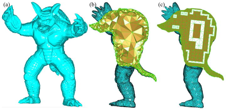
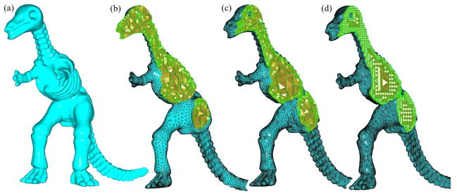
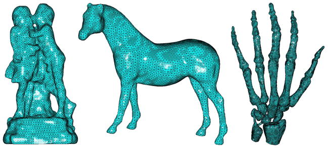
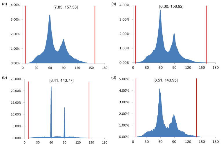
To demonstrate the effectiveness of our method, we compare it with two related methods, including Tetgen [40, 41] and Netgen [42]. For the Netgen, we use all default parameters to generate tetrahedral meshes. For the Tetgen, the quality mesh option is set. In our method, the main parameter is the max depth of the octree subdivision. According to our experimental tests, the max depth of 6 always yields good results. Fig. 17 gives the tetrahedral mesh generation results of the armadillo surface mesh by using Tetgen and our method. The corresponding dihedral angle histograms of the generated meshes are shown in Fig. 18. Similarly Fig. 19, Fig. 21, Fig. 23 and Fig. 25 give the tetrahedral meshes of the dinosaur, dragon, molecule and teeth triangular meshes, generated by Netgen, Tetgen and our method, while Fig. 20, Fig. 22, Fig. 24 and Fig. 26 present the corresponding dihedral angle histograms. Fig. 27 gives additional testing examples. Due to the BCC technique used, the majority of the tetrahedra generated by our method have dihedral angles at 60° and 90°, corresponding to the two peaks in the angle histograms. Compared to those of Netgen and Tetgen, our histograms look less smooth. However, the smoothness of a histogram is not necessarily related to the quality of a mesh. For instance, a smooth histogram may have a great number of very small or large angles, while dihedral angles in an ideal mesh are expected to be uniform, resulting in a very sparse histogram.
Figure 17.
Tetrahedral mesh generation of the the armadillo model. (a) The original surface mesh. (b) The tetrahedral mesh generated by Tetgen (44, 084 vertices) and (c) By our method (31, 855 vertices).
Figure 18.
Dihedral angle histograms of the tetrahedral meshes in Fig. 17(b–c), respectively. The corresponding angle bounds are given. From the figure, the dihedral angles of the mesh generated by our method are mainly distributed around 60° and 90°.
Figure 19.
Tetrahedral mesh generation of the dinosaur model. (a) The original surface mesh. (b) The tetrahedral mesh generated by Netgen (31, 838 vertices), (c) By Tetgen (37, 644 vertices) and (d) By our method (35, 234 vertices).
Figure 21.
Tetrahedral mesh generation of the dragon model. (a) The original surface mesh. (b) The tetrahedral mesh generated by Tetgen (184, 880 vertices). (c) By our method (147, 397 vertices). Due to a huge number of tetrahedra, we did not display the edges here. Otherwise, it would be too dark to see the mesh details.
Figure 23.
Tetrahedral mesh generation of a molecule mesh. (a) The original surface mesh. (b) The tetrahedral mesh generated by Netgen (20, 505 vertices). (c) By Tetgen (52, 563 vertices). (d) By our method (22, 187 vertices).
Figure 25.
Tetrahedral mesh generation of the teeth model. (a) The original surface mesh. (b) The tetrahedral mesh generated by Netgen (38, 426 vertices). (c) By Tetgen (56, 530 vertices). (d) By our method (16, 180 vertices).
Figure 20.
Dihedral angle histograms of the tetrahedral meshes in Fig. 19(b–d), respectively. Most of the dihedral angles of the meshes generated by Netgen and Tetgen are distributed around 60°, but the minimum dihedral angles are very small. Among these three methods, ours gives the highest angle quality in terms of minimal dihedral angles.
Figure 22.
Dihedral angle histograms of the tetrahedral meshes in Fig. 21(b,c), respectively.
Figure 24.
Dihedral angle histograms of the tetrahedral meshes in Fig. 23(b–d), respectively.
Figure 26.
Dihedral angle histograms of the tetrahedral meshes in Fig. 25(b–d), respectively. Again, the angle quality of the mesh is higher by our method, compared with two other methods.
Figure 27.
Additional mesh generation results from the hand, horse and sculpture surface mesh models.
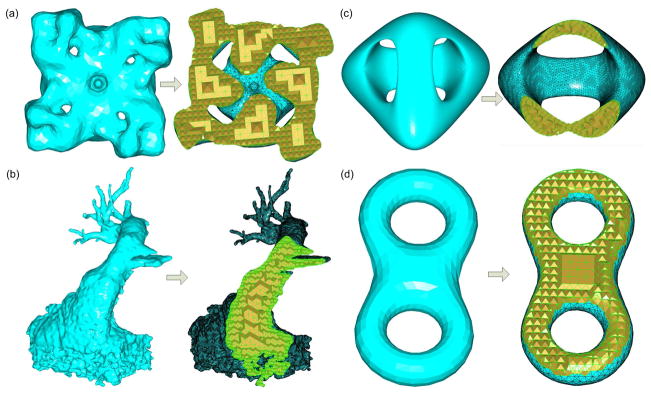
To verify the robustness of our method, we have tested some more complex surface models with high genus (> 1), which are common and useful for some real applications. Fig. 28 shows the tetrahedral meshes from some complex surface models using our method, where Fig. 28(a) is the result from a molecule model (genus = 4); Fig. 28(b) is the mesh generation result of a heart surface model; Fig. 28(c) and Fig. 28(d) present results from two typical surface models (genus = 2, 3, respectively). Fig. 29 gives the corresponding dihedral angle histograms of those four models. From the histograms, our method still has good performance on those complex surface models.
Figure 28.
Mesh generation results from some complex surface models. (a) Molecule model (genus = 4); (b) Heart surface model; (c) Surface model (genus = 3); (d) Surface model (genus = 2)
Figure 29.
The corresponding dihedral angle histograms of the tetrahedral meshes from the surface models in Fig. 28
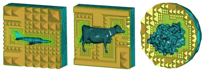
In some applications, the exterior tetrahedral mesh between the surface mesh and an bounding box/sphere is needed for the simulation purpose. Fig. 30 shows such tetrahedral meshes of the aircraft, cow and 1TIM molecule mesh models generated by our method.
Figure 30.
Additional mesh generation results from the aircraft, cow and 1TIM molecule mesh models. Note that the tetrahedral meshes are generated between the original surface meshes and the user-defined bounding boxes or spheres.
From the results, most of the dihedral angles of the meshes are distributed around 60° generated by Netgen and Tetgen, while those from our method are mainly distributed around 60° and 90°. The minimum dihedral angles are quite small (even close to zero in some cases) from Netgen and Tetgen. By contrast, our method always produces tetrahedral meshes with larger minimal dihedral angles.
With our method, the boundary surface mesh of the generated tetrahedral mesh is different from the original surface mesh. To demonstrate the fidelity of the generated boundary surface mesh relative to the original mesh, the Hausdorff distance between the two meshes is calculated with the software tool called Metro [43]. Figure 31 shows a detailed comparison of the Hausdorff distance results, where the horizontal axis is the absolute distance value between the boundary surface mesh and the original mesh, and the vertical axis is the corresponding histogram (in percentage) with respect to each distance value. From these histograms, the boundary surface mesh from Tetgen has the smallest error to the original surface mesh among three methods. Our method has almost the same result as Netgen. In general, the boundary mesh by our method has good fidelity to the original mesh.
Figure 31.
The histogram shows the Hausdorff distance between the original surface mesh and the boundary surface mesh of the tetrahedral mesh generated by three approaches. The meshes are both scaled into a unit cube. The horizontal axis is the error (absolute distance value) between the boundary surface mesh and the original surface mesh, and the vertical axis is the corresponding percentage to each error value.
Table 2 shows the computational times of the aforementioned models by Netgen, Tetgen and our method, where N/A means failure of mesh generation. From the result, our method is slower than Tetgen but faster than Netgen. For the big heart model containing 817,352 tetrahedra, our method takes less than 9 minutes. In addition, Tetgen and Netgen both fail to generate the tetrahedral mesh of the heart model, while our method still produces a good result. Overall, our method achieves a good combination of efficiency and effectiveness in terms of computational time, robustness, and mesh quality.
Table 2.
Comparisons of computational time (in seconds)
| Models | Number of tetrahedra | Octree subdiv. time | Mesh gen. time | Total time | ||
|---|---|---|---|---|---|---|
| our | Tetgen | Netgen | ||||
| Bunny | 46,518 | 12.248 | 0.568 | 12.816 | 6.715 | 19.191 |
| 2CMP | 42,323 | 16.703 | 0.530 | 17.233 | 14.253 | 37.834 |
| Teeth | 63,957 | 27.740 | 0.958 | 28.698 | 16.905 | 86.798 |
| Molecule | 102,947 | 29.747 | 1.345 | 31.092 | 16.284 | 107.542 |
| Dinosaur | 143,162 | 54.251 | 2.219 | 56.470 | 10.262 | 163.267 |
| Armadillo | 130,213 | 60.559 | 2.013 | 62.572 | 16.404 | N/A |
| Dragon | 630,201 | 457.216 | 9.693 | 466.909 | 108.944 | N/A |
| Heart | 817,352 | 532.388 | 11.281 | 543.669 | N/A | N/A |
5. Conclusion and Future Work
In this paper, we propose a robust meshing algorithm for tetrahedral mesh generation from a surface mesh. Motivated by good characteristics of the BCC lattice, the cutting point snapping strategy and the optimal decomposition technique are performed over the BCC lattice to obtain the adaptive, quality-guaranteed tetrahedral meshes. The minimum dihedral angle could be more than 10° if a uniform is generated on the boundary of the surface mesh. When adaptive meshes are required on the surface, our method is still capable of producing tetrahedral meshes with the minimum dihedral angle being guaranteed to be greater than or equal to 5.71°.
Compared with the two current popular methods, Tetgen and Netgen, our method is more robust and general. According to the experiments, Tetgen and Netgen typically require the input surface meshes have good quality. If the quality of the input mesh is poor, like self-intersection or non-manifold, the mesh generation often fail. With our approach, however, there is no quality requirement for the input surface mesh. The prices paid in our approach, however, is that the boundary mesh of the produced tetrahedral mesh is often geometrically an approximation of the original surface mesh. Our method is inappropriate if the input surface mesh is required to be precisely preserved in the output tetrahedral mesh.
Over two decades, it has been very challenging to generate tetrahedral meshes with guaranteed quality, while preserving sharp features. Similarly, our algorithm can not preserve sharp edges or corners either. We also tried the dual contouring idea [44] to retain sharp features. While the sharp features are reconstructed better, the dihedral angles of the tetrahedral meshes near the features decrease to very small values. Therefore, in our future work, we would like to study how to generate a quality-guaranteed and feature-preserved tetrahedral mesh from a general surface mesh.
While the current paper is focused on two essential issues (i.e., minimal dihedral angles and mesh adaptivity) in one of the most commonly used mesh types (i.e., tetrahedral meshes), there are different ways to measure the quality of a tetrahedral mesh and different types of meshes (including parabolic tetrahedral meshes) used for numerical simulation. Re-designing the described approaches to address these additional issues would provide some new perspectives in volumetric mesh generation and numerical analysis.
Figure 14.
Angle histograms of (a) the original 2CMP molecular mesh, (b) the boundary surface mesh of the generated tetrahedral mesh, and (c) the histogram of the dihedral angle of the tetrahedral mesh.
Highllights.
For an arbitrary surface mesh model, a high-quality tetrahedral mesh generation algorithm is proposed;
The smallest dihedral angle of tetrahedral meshes is always greater than 5.71 degree;
The tetrahedral meshes are not only adaptive from the interior to the boundary, but also feature-sensitive on the surface with denser elements in high-curvature regions where geometric feature most likely reside.
Acknowledgments
The work described was supported in part by an NIH Award (Number R15HL103497) from the National Heart, Lung, and Blood Institute (NHLBI) and by a subcontract from the National Biomedical Computation Resource (NIH Award Number P41 RR08605). The content is solely the responsibility of the authors and does not necessarily represent the official views of the sponsors.
Footnotes
Publisher's Disclaimer: This is a PDF file of an unedited manuscript that has been accepted for publication. As a service to our customers we are providing this early version of the manuscript. The manuscript will undergo copyediting, typesetting, and review of the resulting proof before it is published in its final citable form. Please note that during the production process errors may be discovered which could affect the content, and all legal disclaimers that apply to the journal pertain.
References
- 1.Shewchuk J. What Is a Good Linear Element? Interpolation, Conditioning, and Quality Measures. Proc. 11th Intl. Meshing Roundtable; 2002. [Google Scholar]
- 2.George P, Frey P. Mesh Generation. 2. Wiley; 2008. [Google Scholar]
- 3.Frey P, Borouchaki H, George P. Delaunay Tetrahedralization Using an Advancing Front Approach. Proc. of 5th Intl. Meshing Roundtable; 1996. [Google Scholar]
- 4.Miller G, Talmor D, Teng S, Walkington N, Wang H. Control Volume Meshes using Sphere Packing: Generation, Refinement and Coarsening. Proc. of 5th Intl. Meshing Roundtable; 1996. [Google Scholar]
- 5.Borouchaki H, George P, Hecht F, Laug P, Saltel E. Delaunay mesh generation governed by metric specifications. Part 1 : Algorithms. Finite Elements in Analysis and Design. 1997;25:61–83. [Google Scholar]
- 6.Borouchaki H, George P, Mohammadi B. Delaunay mesh generation governed by metric specifications. Part 2 : Application examples. Finite Elements in Analysis and Design. 1997;25:85–109. [Google Scholar]
- 7.Chew P. Guaranteed-Quality Delaunay Meshing in 3D. Proc. 19th Annu. Sympos. Comput. Geom; 1997. pp. 274–280. [Google Scholar]
- 8.Owen S. A Survey of Unstructured Mesh Generation Technology. Proc. 7th Intl. Meshing Roundtable; 1998. [Google Scholar]
- 9.Shewchuk J. Trtrahedral Mesh Generation by Delaunay Refinement. Prof. 14th Annu. Sympos. Comput. Geom; 1998. [Google Scholar]
- 10.Du Q, Faber V, Gunzburger M. Centroidal Voronoi Tesselations: Applications and Algorithms. SIAM Review. 1999;41(4):637676. [Google Scholar]
- 11.Shewchuk J. Mesh Generation for Domains with Small Angles. Proc 16th Annu. ACM Sympos. Comput. Geom; 2000. [Google Scholar]
- 12.Cohen-Steiner D, De Verdiere E, Yvinec M. Conforming Delaunay triangulations in 3D. Proc. of Symp. on Comp. Geom; 2002. pp. 237–246. [Google Scholar]
- 13.Cheng S, Poon S. Graded conforming Delaunay tetrahedralization with bounded radius-edge ratio. Proc. of the 14th ACM-SIAM Symposium on Discrete algorithms; 2003. pp. 295–304. [Google Scholar]
- 14.Cheng W, Dey T, Edelsbrunner H, Facello M, Teng S. Sliver Exudation. J ACM. 1999;47:883–904. [Google Scholar]
- 15.Oudot S, Rineau L, Yvinec M. Meshing Volumnes Bounded by Smooth Surfaces. Proc. the 14th Intl. Meshing Roundtable; 2005. pp. 203–219. [Google Scholar]
- 16.Edelsbrunner H, Guoy D. An Experimental Study of Sliver Exudation. Proc. 10th Intl. Meshing Roundtable; 2001. p. 307316. [Google Scholar]
- 17.Alliez P, Cohen-Steiner D, Yvinec M, Desbrun M. Variational Tetrahedral Meshing. ACM Transactions on Graphics. 2005;24(3):617625. Special issue on Proceedings of SIGGRAPH 2005. [Google Scholar]
- 18.Dardenne J, Valette S, Siauve N, Prost R. Variational Tetrahedral Mesh Generation from Discrete Volume Data. The Visual Computer. 2009;25(5):401–410. Special issue on Proceedings of CGI 2009. [Google Scholar]
- 19.Tournois J, Wormser C, Alliez P, Desbrun M. Interleaving Delaunay Refinement and Optimization for Practical Isotropic Tetrahedron Mesh Generation. ACM/SIGGRAPH Transactions on Graphics. 2009;28(3) [Google Scholar]
- 20.Freitag LA, Ollivier-Gooch C. Tetrahedral Mesh Improvement Using Swapping and Smoothing. International Journal for Numerical Methods in Engineering. 1997;40(21):3979–4002. [Google Scholar]
- 21.Choi W, Kwak D, Son I, Im Y. Tetrahedral Mesh Generation based on Advancing Front Technique and Optimization Scheme. International Journal for Numerical Methods in Engineering. 2003;58:18571872. [Google Scholar]
- 22.Li X. PhD thesis. University of Illinois; Urbana-Champaign: 2000. Sliver-free 3-Dimensional Delaunay Mesh Generation. [Google Scholar]
- 23.Marcum D, Weatherill N. Shape Reconstruction and Volume Grid Generation using Iterative Point Insertion and Meshing for Complex Solids. AIAA Journal. 1995;33(9):1619–1625. [Google Scholar]
- 24.Ito Y, Shih AM, Soni BK. Reliable Isotropic Tetrahedral Mesh Generation Based on an Advancing Front Method. Proc. 10th Intl. Meshing Roundtable; 2004. pp. 95–106. [Google Scholar]
- 25.Garimella R, Shephard M. Boundary Layer Meshing for Viscous Flows in Complex Domains. Proc. 7th Intl. Meshing Roundtable; 1998. pp. 107–118. [Google Scholar]
- 26.Lohner R, Cebral J. Generation of Non-Isotropic Unstructured Grids via Directional Enrichment. Proc. 2nd Symp. on Trends in Unstructured Mesh Generation; 1999. [Google Scholar]
- 27.Molino N, Bridson R, Teran J, Fedkiw R. A Crystalline, Red Green Strategy for Meshing Highly Deformable Objects with Tetrahedra. Proc. of the 12th Intl. Meshing Roundtable; 2003. pp. 103–114. [Google Scholar]
- 28.Yerry M, Shephard M. Automatic Three-Dimensional Mesh Generation by the Modified-Octree Technique. International Journal for Numerical Methods in Engineering. 1984;20(11):19651990. [Google Scholar]
- 29.Fuchs A. Automatic Grid Generation with Almost Regular Delaunay Tetrahedra. Proc. 7th Intl. Meshing Roundtable; 1998. pp. 133–148. [Google Scholar]
- 30.Naylor D. Filling Space with Tetrahedra. International Journal for Numerical Methods in Engineering. 1999;44(10):1383–1395. [Google Scholar]
- 31.Schindler R, Weiler F. Octree-based Generation of Hexahedral Element Meshes. Proc. 5th Intl. Meshing Roundtable; 1996. pp. 205–216. [Google Scholar]
- 32.Boyd SK, Muller R. Smooth Surface Meshing for Automated Finite Element Model Generation from 3D Image Data. Journal of Biomechanics. 2006;39:1287–1295. doi: 10.1016/j.jbiomech.2005.03.006. [DOI] [PubMed] [Google Scholar]
- 33.Ito Y, Shih AM, Soni BK. Octree-based Reasonable-quality Hexahedral Mesh Generation using a New Set of Refinement Templates. International Journal for Numerical Methods in Engineering. 2009;77:1809–1833. [Google Scholar]
- 34.Zhang Y, Bajaj C, Sohn S. 3D finite element meshing from imaging data. Computer Methods in Applied Mechanics and Engineering. 2005;194(48–49):50835106. doi: 10.1016/j.cma.2004.11.026. Special issue on Unstructured Mesh Generation. [DOI] [PMC free article] [PubMed] [Google Scholar]
- 35.Zhang Y, Bajaj C. Adaptive and Quality Quadrilateral/Hexahedral Meshing from Volumetric Data. Computer Methods in Applied Mechanics and Engineering. 2006;195(9–12):942960. doi: 10.1016/j.cma.2005.02.016. [DOI] [PMC free article] [PubMed] [Google Scholar]
- 36.Labelle F, Shewchuk J. Isosurface Stuffing: Fast Tetrahedral Meshes with Good Dihedral Angles. ACM Transactions on Graphics. 2007;26(3):57. [Google Scholar]
- 37.Yu Z, Holst M, McCammon J. High-fidelity geometric modeling for biomedical applications. Finite Elem in Anal and Des. 2008;44:715–723. [Google Scholar]
- 38.Yu Z. A List-based Method for Fast Generation of Molecular Surfaces. Proc. 31st Intl. Conf. of IEEE Engineering in Medicine and Biology Society; 2009. pp. 5909–5912. [DOI] [PMC free article] [PubMed] [Google Scholar]
- 39.Wang J, Yu Z. A Novel Method for Surface Mesh Smoothing: Applications in Biomedical Modeling. Proc. 18th Intl. Meshing Roundtable; 2009. pp. 195–210. [Google Scholar]
- 40.Si H. Adaptive Tetrahedral Mesh Generation by Constrained Delaunay Refinement. Int J Numer Meth Engrg. 2008;75:856–880. [Google Scholar]
- 41.TetGen - A Quality Tetrahedral Mesh Generator and a 3D Delaunay Triangulator. 2009 viewed May 26, 2011; http://tetgen.berlios.de.
- 42.NETGEN - automatic mesh generator. 2009 viewed May 26, 2011 http://www.hpfem.jku.at/netgen.
- 43.Cignoni P, Rocchini C, Scopigno R. Metro: measuring error on simplified surfaces. Computer Graphics Forum. 1998;17(2):167–174. [Google Scholar]
- 44.Ju T, Losasso F, Schaefer S, Warren J. Dual Contouring of Hermite Data. ACM Transactions on Graphics. 2002;21(3) [Google Scholar]


