

Abstract
The use of rigid connectors in 5-unit fixed dental prosthesis with a pier abutment can result in failure of weaker retainer in the long run as the pier abutment acts as a fulcrum. Non-rigid connector placed on the distal aspect of pier seems to reduce potentially excess stress concentration on the pier abutment.
Keywords: Matrix, non-rigid connectors, patrix, pier
Introduction
Connectors, the portion of a fixed dental prosthesis that unites the retainer(s) and pontic are considered as heartthrob of abutments, since under occlusal load maximum stresses are concentrated on them. Selection of the right type of connector can make a real difference between success and failure. We are more accustomed to the use of rigid connector in clinical practice since its placement requires minimum technical and laboratory expertise. The real problem arises when we encounter 5-unit fixed dental prosthesis (FDP) with a pier abutment. Teeth in different segments of the arch move in different directions. Because of the curvature of the arch, the faciolingual movement of anterior tooth occurs at a considerable angle to the faciolingual movement of molar tooth. These movements can create stresses on the abutments in long-span prosthesis. A non-rigid connector, a stress breaking mechanical union of retainer and pontic, is usually recommended in such situation.[1–6]
Case Report
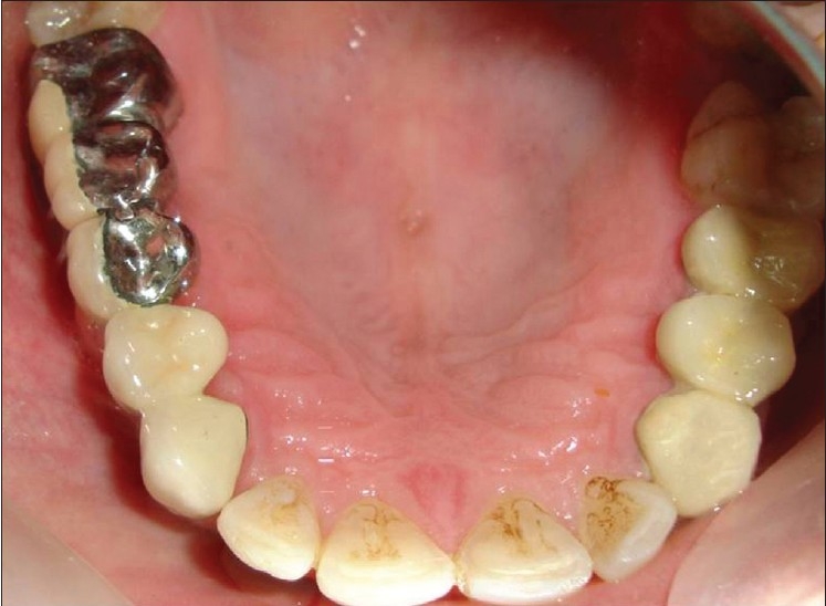
A 26 year-old male patient [Figure 1] reported to the Department of Prosthetic Dentistry with missing teeth #14 and #16, and he had difficulty in chewing and esthetic problems. On examination it was found that the patient had canine-guided occlusion bilaterally. Caries was found in #24, which was later extracted and an FDP was fabricated. Radiologically and clinically, the abutment teeth were having favourable criteria. After discussing all the treatment options and their pros and cons, it was decided to rehabilitate the case with 5-unit FDP using non-rigid connectors on the distal aspect of pier abutment. A semi-precision attachment named plastic dovetail (Stern gold Attachments, Attleboro, MA, USA) [Figure 2] was selected in this case. It had frictional retention, plastic pattern male and female, with built in paralleling mandrels.
Figure 1.
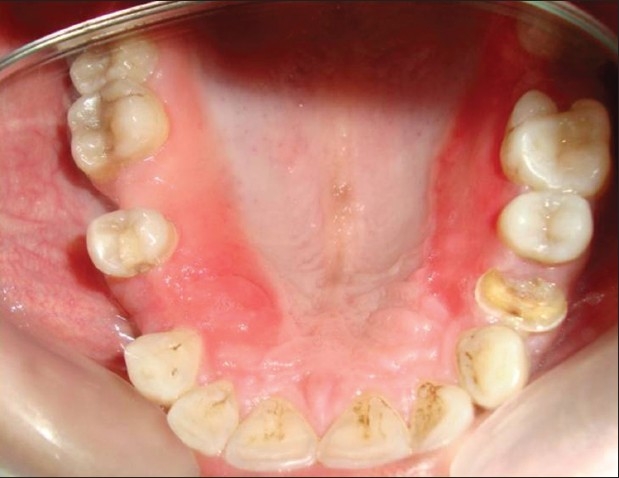
Intraoral preoperative view
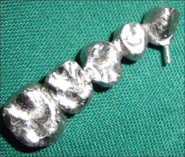
Figure 2.
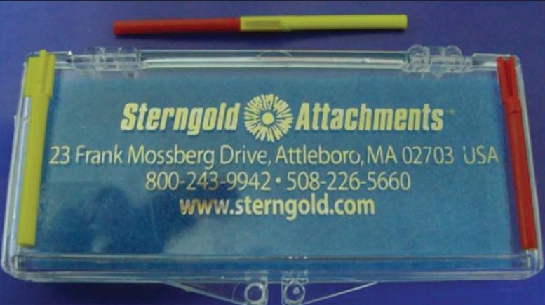
Semi-precision attachment – plastic dovetail
Fixation: Male/patrix cast as part of pontic pattern; female/matrix cast as part of crown pattern.
Space requirements: height – 2 mm, preparation depth – 2 mm, width – 2.6 mm.
Procedure
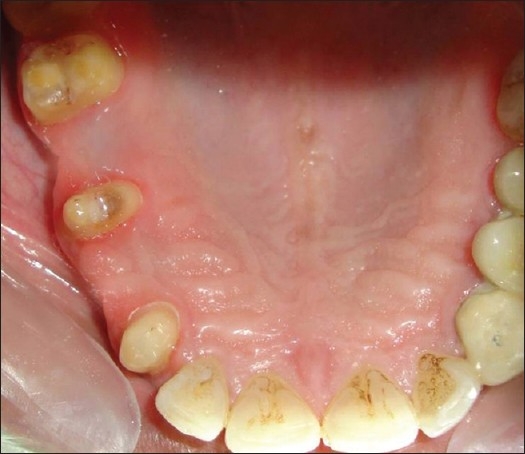
Tooth preparations were completed [Figure 3] and impression was taken with poly (vinyl siloxane) impression material.
Wax pattern was fabricated and recess for the female was cut accordingly to fit the plastic dovetail on distal aspect of pier abutment.
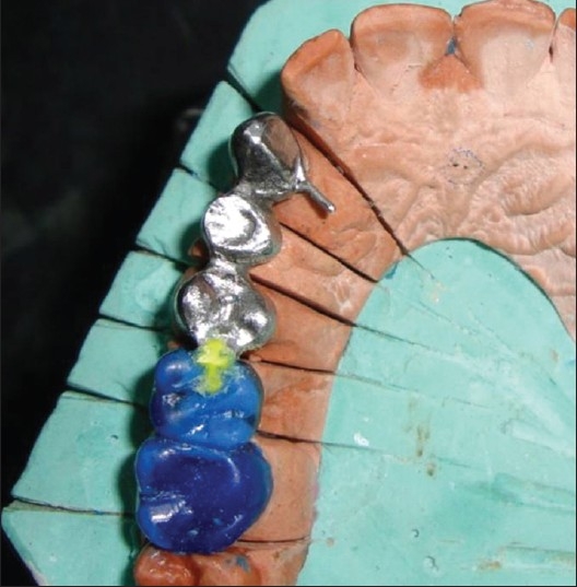
Surveying was done to determine the position/parallelism of plastic dovetail [Figure 4].
Plastic dovetail female was placed within the correct contour of the abutment tooth. Male pattern was removed from the female pattern, keeping the inside of female pattern free of wax. Any extension of the female pattern above the occlusal of the abutment was left remaining.
After investing and casting, excess height of the female was reduced, metal try-in of the part with the matrix/female was done [Figure 5].
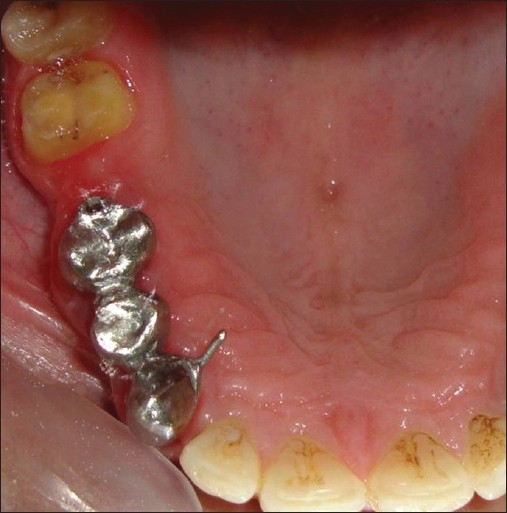
Male/patrix pattern was seated in the casted female. Adjacent pontic and abutment were waxed up and the mandrel was cut off from the male [Figure 6]. Casting of the male pattern was contemplated.
Now matrix and patrix were assembled together [Figure 7].
Ceramization was done on #13, #14 and buccal facing was done on #15, #16, and #17. The prosthesis was cemented with glass ionomer cement [Figures 8–10].
Figure 3.
Tooth preparation
Figure 4.
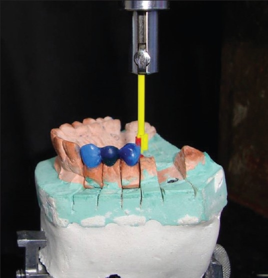
Surveying done to check the parallelism
Figure 5.
Metal try-in of the part with the matrix
Figure 6.
Wax pattern of patrix
Figure 7.
Matrix and patrix assembled together
Figure 8.
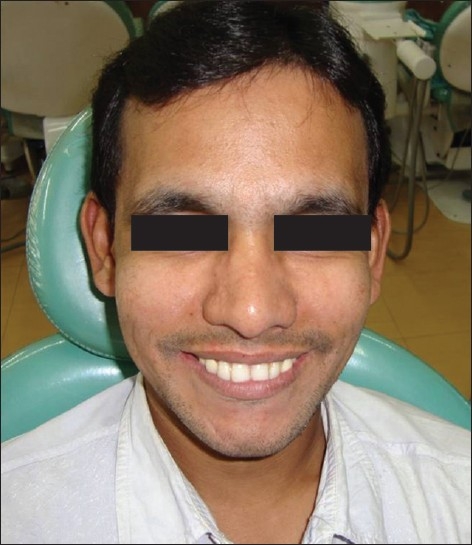
Postoperative view in smile
Figure 10.
Postoperative occlusal view
Figure 9.
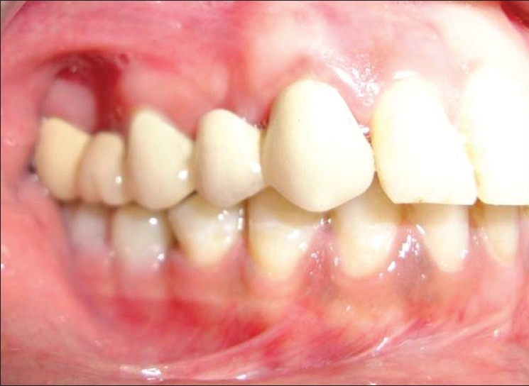
Postoperative intraoral buccal view
Discussion
With rigid connectors, an occlusal load applied on the abutment tooth at one end of an FDP (mainly the molar retainer) with a pier abutment, the pier may act as a fulcrum. Tensile forces may then be generated between the retainer and abutment at the other end of the restoration (in the canine retainer). Anterior or posterior abutments may experience extrusive force and the resultant tensile force at the retainer to abutment interface may lead to potential loss of retention for these restorations, thus resulting in marginal leakage, caries of abutment, and FDP failure.[1–6]. Non-rigid connector is usually recommended in such a situation.
There is a conflicting opinion on where to place the non-rigid connector. Markley[1] suggested placement on one of the terminal abutments and not at the pier abutment. Adams[2] suggested placing the connector at the distal side of pier, and if desired, adding one more at the distal side of the anterior retainer, while Gill[3] suggested placing it at one side or both sides of the pier.
Shillingberg[4] suggested placing the connector at the distal aspect of pier abutment. Since the long axis of the posterior teeth usually leans slightly in a mesial direction, vertically applied occlusal forces produce further movement in this direction. This would nullify the fulcrum effect and the patrix/male of the attachment would be seated firmly in place when pressure is applied distally to the pier. This position has been supported by finite element analysis study[5] done by Oruc et al. In this case, we have placed it on distal aspect of the pier.
The contraindications of using a non-rigid connector in a posterior 5-unit FPD with a pier are as follows:
Significant mobility of abutments.
If the span between the abutments is longer than one tooth.
If the distal retainer and pontic are opposed by a removable partial denture or an edentulous ridge, while the two anterior retainers are opposed by natural dentition, allowing the distal terminal abutment to supraerupt.[4–6]
Conclusion
The bonhomie of rigid and non-rigid connectors can increase the life span of an abutment in 5-unit FDPs as it transfers less stress on the abutments. Also, allowing physiologic tooth movement, it eliminates any hindrance as against a fixed restoration with all rigid connectors. A small amount of time spent can be a miracle in the long run. The selection of right type of connector is an important step when sorting treatment plan.
Footnotes
Source of Support: Nil.
Conflict of Interest: None declared.
References
- 1.Markley MR. Broken-stress principle and design in fixed bridge prosthesis. J Prosthet Dent. 1951;1:416–23. doi: 10.1016/0022-3913(51)90027-3. [DOI] [PubMed] [Google Scholar]
- 2.Adams JD. Planning posterior bridges. J Am Dent Assoc. 1956;53:647–54. doi: 10.14219/jada.archive.1956.0236. [DOI] [PubMed] [Google Scholar]
- 3.Gill JR. Treatment planning for mouth rehabilitation. J Prosthet Dent. 1952;2:230–45. [Google Scholar]
- 4.Shillingburg HT, Jr, Hobo S, Whitsett LD, Jacobi R, Brackett SE. 3rd ed. Chicago: Quintessence; 1997. Fundamentals of fixed prosthodontics; pp. 85–118. [Google Scholar]
- 5.Oruc S, Eraslan O, Tukay HA, Atay A. Stress analysis of effect of non rigid connectors on fixed partial dentures with pier abutments. J Prosthet Dent. 2008;99:185–92. doi: 10.1016/S0022-3913(08)60042-6. [DOI] [PubMed] [Google Scholar]
- 6.Savion I, Saucier CL, Rues S, Sadan A, Blatz M. The pier abutment: A review of literature and suggested mathematical model. Quintessence Int. 2006;37:345–52. [PubMed] [Google Scholar]