Abstract
RF transceiver array design using primary and higher order harmonics for in-vivo parallel MR imaging and spectroscopic imaging is proposed. The improved electromagnetic decoupling performance, unique magnetic field distributions and high-frequency operation capabilities of higher-order harmonics of resonators would benefit transceiver arrays for parallel MRI, especially for ultrahigh field parallel MRI. To demonstrate this technique, microstrip transceiver arrays using first and second harmonic resonators were developed for human head parallel imaging at 7T. Phantom and human head images were acquired and evaluated using the GRAPPA reconstruction algorithm. The higher-order harmonic transceiver array design technique was also assessed numerically using FDTD simulation. Compared with regular primary-resonance transceiver designs, the proposed higher-order harmonic technique provided an improved g-factor and increased decoupling among resonant elements without using dedicated decoupling circuits, which would potentially lead to a better parallel imaging performance and ultimately faster and higher quality imaging. The proposed technique is particularly suitable for densely spaced transceiver array design where the increased mutual inductance among the elements becomes problematic. In addition, it also provides a simple approach to readily upgrade the channels of a conventional primary resonator microstrip array to a larger number for faster imaging.
Keywords: Decoupling, harmonics, head, high field, microstrip transmission line resonator, parallel imaging, RF coil array
I. Introduction
TRANSCEIVER arrays, capable of independent RF transmission and independent MR signal reception by the array elements, have been proven to be a popular solution to specific absorption rate (SAR) issues, B1 shimming/manipulation and parallel excitation for high and ultrahigh field MR [1]–[6]. Due to the large field-of-view (FOV), B1 inhomogeneity, long excitation time taken in selective excitation and higher power requirement in human high field MR applications, the advantages and necessity of using transceiver arrays, rather than receiver arrays, become particularly prominent [7]–[10]. One of the major challenges in design of such transceiver arrays is to attain sufficient electromagnetic (EM) decoupling among the resonant elements [1], [3], [10]–[14]. The design becomes particularly difficult when the resonant elements are densely placed and with a large number of elements in order to increase its parallel imaging performance [1], [15], [16]. The decoupling method of using low input impedance preamplifiers commonly used for receiver array designs [17] is not readily to be implemented in the transceiver designs due to the required high RF power during the transmit (or excitation) phase. In the transceiver array design with regular loop elements, a decoupling network which usually is a LC circuit [11], [18] or simply a capacitor or inductor [19], is required to achieve the needed decoupling [12], [20]. Compared with the regular loop coil elements, microstrip coils have demonstrated improved decoupling performance owing to their confined EM fields [1], [2], [21]–[23]. A decoupling network between two adjacent array elements is employed to further enhance the decoupling performance of microstrip design when the array elements are densely spaced for high acceleration rate [1], [10]. At ultrahigh fields, the value of the capacitors used in such decoupling network falls into a small number in the range of a few picofarad [24], [25]. With the increase of static magnetic field strength, the decoupling capacitance might be impractically small in in-vivo applications, ultimately making the decoupling method difficult to implement, and the decoupling performance is extremely sensitive to the subjects or loading, making the decoupling unstable [24], [25]. Therefore it would be ideal if there are no decoupling circuits employed in the transceiver arrays. Besides the decoupling issue, it is also desirable in designing parallel imaging arrays that each element should have a different or unique B1 profile in order to attain a better g-factor and thus better parallel imaging performance.
RF coil designs using high-order harmonics have been advocated for ultrahigh field in vivo MR applications [26]–[29]. One of the advantages of this technology is its unique capability of high frequency operation [26] which is essential to large-size coil designs for ultrahigh field MRI in humans. In contrast to the primary resonance (or first harmonic) that is conventionally used for RF coil or coil array designs, the high order harmonics, e.g. the second harmonics, have a completely different B1 field distribution. Yet, theoretically a first harmonic resonator and a second harmonic resonator placed in parallel are electromagnetically decoupled. These features of the high order harmonics would be beneficial to parallel imaging coil array designs for ultrahigh field MRI applications in humans [27].
In this work, we propose a transceiver array design technique for ultrahigh field parallel imaging applications in humans. The proposed design utilizes a mix of first harmonic resonators and second harmonic resonators as the resonant elements of the transceiver array. In this design, the first and second harmonic resonators are implemented using microstrip technology which has been proven to be advantageous for ultrahigh field RF coil designs [2], [21], [23], [30], [31] due to its improved resonance stability and reduced radiation losses. To demonstrate this technology, 16-channel microstrip arrays with alternately placed first and second harmonic resonant elements are designed and tested at 7T. The proposed transceiver array, capable of performing parallel imaging and parallel excitation for B1 manipulation and selective excitation in humans, provides improved coil decoupling performance without using dedicated decoupling circuits and also yields relatively large coil coverage and improved g-factors due to the different B1 profile of the first and second harmonic microstrip resonators. The unique element decoupling capability makes this proposed technology beneficial to the massively parallel array designs for ultrahigh field MR. Importantly, this technique provides a simple approach to upgrading a conventional array (built with primary resonant elements) to a larger channel number up to double by alternately inserting the high harmonic elements. There is no decoupling network needed for such an upgrade. Bench test and MR proton imaging results obtained from the transceiver array at 7T in phantoms and in the human head are shown to demonstrate its feasibility and performance.
II. Materials and Methods
A. Coil Element Design
The first harmonic and second harmonic resonators were designed and constructed for the proposed transceiver array design using the mixed harmonic resonance technology. Both resonators were implemented using microstrip with the same length. Figure 1 depicts the circuits and current distributions of these resonators. The resonator in Figure 1a is a typical straight-type, first harmonic resonator with two termination capacitors at the two ends of the microstrip for field distribution control and frequency adjustment. Different from the first harmonic resonator, the second harmonic resonator had an additional capacitor shunted at the center of the microstrip in order to have a symmetric field distribution, as shown in Figure 1b. This shunt capacitor can also be utilized for additional frequency tuning. Before adding the termination capacitors and shunt capacitor on the microstrip, the second harmonic resonance was double the resonance frequency of the primary (or first harmonic) resonance [26], [27]. With different current distributions as illustrated in Figure 1, the magnetic fluxes of the first and second harmonic resonators are are canceled, achieving an intrinsic decoupling if the two resonators are placed in parallel.
Fig. 1.
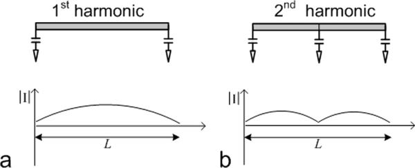
Schematic of straight-type microstrip resonators and current distributions along resonators, (a) primary or first harmonic microstrip resonator. (b) the second harmonic microstrip resonator. In this study, the resonant frequency of these two types of microstrip resonators is tuned to the proton Larmor frequency at 7T.
The equations for calculating the frequency of the first or second harmonic resonance on a microstrip resonator with the termination capacitors can be derived using the ABCD matrix method. For the second harmonic circuit with shunt and termination capacitors as depicted in Figure 2a, for convenience, assume that the termination capacitors at the two ends have the same value C1, and that the center capacitor is C2. Its symmetric equivalent structure along the dash line is shown in Figure 2b. According to “magnetic/electric wall” analysis [32], [33], the symmetry circuit can be analyzed by inserting an open circuit (magnetic wall) and a short circuit (electric wall) into the dash line. Any bisection magnetic and electric circuit, which is shown in Figure 2c is used to calculate the resonance frequencies with the first and second harmonics.
Fig. 2.
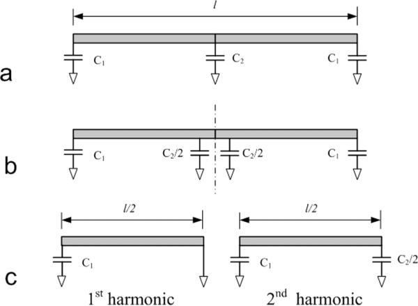
Model established to calculate the resonance frequencies of 1st and 2nd harmonic in a microstrip resonator. The circuit in (a) can be changed into the symmetric structure along the central dashed line shown in (b). Applying short circuit and open circuit along the dashed line, respectively, the two resonance frequencies (1st and 2nd harmonic frequencies) can be calculated based on the simplified circuits shown in (c).
For the primary resonance mode shown in Figure 2c, the ABCD matrix is expressed as follows.
| (1) |
where ω and Z0 are angular frequency and characteristic impedance, respectively. θ denotes the electric length of the microstrip,
| (2) |
where λ is wavelength within the dielectric material and 1 is the length of the microstrip. Assuming the input port is on the left side of the circuit in Figure 2c (left), the input admittance Yin can be expressed by the following equation since the loading impedance ZL= 0 (short circuit),
| (3) |
For the resonance condition Yin = 0, the primary resonance frequency is obtained.
| (4) |
where f1st = ω/2π. Similarly, when the microstrip coil is loaded with samples, considering the losses and permittivity introduced, the primary resonance frequency is derived as:
| (5) |
where r is propagation constant.
For the circuit shown in Figure 2c (right), its ABCD matrix may be represented in the form:
| (6) |
Since the loading impedance ZL = ∞ (open circuit), the input admittance Yin is:
| (7) |
The second harmonic resonance frequency can then be obtained:
| (8) |
In a special case when C1 and C2 are not equal to 0, the 2nd harmonic frequency can be expressed as
| (9) |
where f2nd=ω/2π. Similarly, when the microstrip coil is loaded with samples, the second harmonic frequency can be calculated using the following equation:
| (10) |
Note that the second harmonic frequency f 2nd is not double of the primary frequency f 1st due to the involved shunt capacitors C1 and C2. For distributed-element microstrip resonators (C1 = C2 = 0), equations (4) and (8) can be simplified and we have f2nd = 2 f1st, which has been indicated in the previous work [26].
Qualitatively, when the transmission lines are loaded with MR samples, the higher permittivity from the sample will result in a longer wavelength λ. According to equation (2), the electrical length θ is reduced accordingly, ultimately leading to decreased f1st and f2nd.
The two resonators with primary and second harmonic resonances were simulated using xFDTD (Remcom Inc. State College, PA) and tested at 7T to investigate their B1 field distributions and signal intensities. The dimensions of these elements were all 16 cm long. The low-loss dielectric material of the microstrip was made of a Teflon sheet with 7 mm thickness. Width of the ground planes and the strip conductors were 3.8 cm and 1.27 cm, respectively. Both the first harmonic and second harmonic resonators were tuned to 298.1 MHz, the Larmor frequency of our GE 7T/90cm scanner (GE Healthcare, Milwaukee, WI) as illustrated in Figure 3 left column. In the simulation, we utilized the same port power for the 1st and 2nd harmonic elements. The coil elements in the simulation have exactly the same structure and dimension (including the shield dimension) as the elements we built for MR imaging experiments.
Fig. 3.
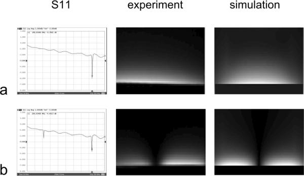
S11 plots and B1 profiles from experiment and simulation results of (a) primary harmonic microstrip resonator and (b) second harmonic microstrip resonator. The image patterns indicate the current or magnetic field distribution of the first and second harmonic resonance in a microstrip resonator.
The MR images, also shown in Figure 3, were acquired along the strip conductors using first and second harmonic resonators with a large cuboid corn oil phantom. The dimension of the oil phantom measured 20 cm × 20 cm × 10 cm. Imaging sequence and parameters were Gradient Recalled Echo (GRE), TR/TE 100ms/6.9 ms, slice thickness 3mm, flip angle 20°. As expected, the image patterns indicate the unique B1 distributions of the first and second harmonic resonators.
FDTD simulation results of the field distribution shown in the right column of Figure 3 were consistent with the experimental results (middle column of Figure 3), indicating the accuracy of the numerical analysis method. Electromagnetic decoupling between the elements was assessed by measuring S21 (i.e. transmission coefficient) on a network analyzer (Agilent, model 4396A). The two coil elements were well decoupled with −27 dB or better isolation when they were placed in parallel as close as 5mm apart. Even when the resonators were tilted, the excellent decoupling performance still remained. This merit of the high-order harmonic array technology could provide a design basis for flexible transceiver arrays for human parallel imaging at high fields [34].
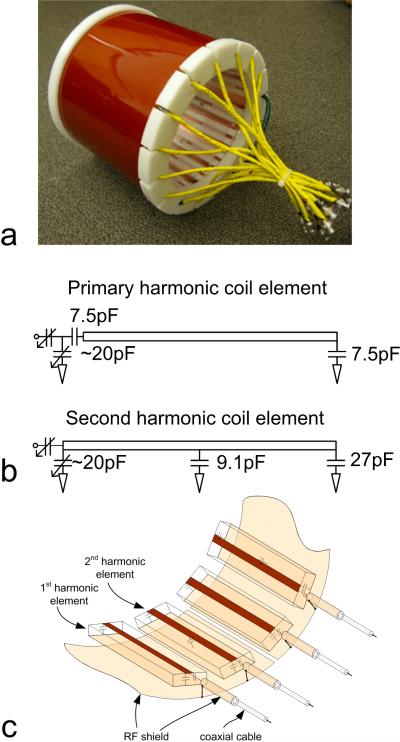
B. Head Array Design
Eight first harmonic elements and eight second harmonic elements were built to form a transceiver array for 1H imaging of the human head in our 7T system. The two types of coil elements were alternately arranged around a cylinder as shown in Figure 4. The coil elements were built on Teflon sheets 20 cm long, 3cm wide and 7 mm thick. The strip conductors and ground planes of the microstrip coil were made of 36-μm-thick adhesive-backed copper tape (3M, St. Paul, MN, USA). The width of the strip conductors was 0.63 cm, and the width of the ground conductor was 2.54 cm. In Figure 4b, the two variable capacitors (Voltronics, Denville, NJ) in the coil elements provided frequency tuning and impedance matching. 8 primary-resonance elements and 8 second-harmonic elements were alternately and evenly stuck at the outside of a plexiglass cylinder with a 22cm diameter. The dimension of this array was selected to fit a typical human head such that a reasonable filling factor could be achieved. The resonance frequency of all coil elements was tuned to 298.1 MHz after loading with a human head. No decoupling network was used to electromagnetically decouple the coil elements. The decoupling performance between any two elements out of all 16 elements was evaluated using transmission coefficient S21 measurements taken on the network analyzer. This 16-element transceiver array was treated as a multi-port, single piece device. Therefore, when any two elements were measured, all the remaining elements were terminated by 50 Ohm loads.
Fig. 4.
Photo of the 7T head transceiver array with alternately placed 1st and 2nd harmonic coil elements based on the proposed mixed harmonic design technique (a), circuits of coil elements (b) and RF shield connection (c).
For this array with densely placed coil elements, the size of the ground plane in each microstrip coil element is not sufficient to provide a perfect ground. Consequently, this transceiver array may suffer from cable resonance, low Q factors and imaging quality degradations. To enhance the coil stability, we utilized an approach [3] to improving the performance of microstrip transceiver arrays by introducing RF shielding outside the microstrip array and the feeding coaxial cables. A cylindrical slotted RF shield with a diameter of 26.7 cm was added to the coil array as shown in Figure 4. The cylindrical shielding had no physical connection with the coil array elements. The distance between the RF shielding and the ground plane of the coil elements was ~1.3 cm. This RF shielding was cut into eight pieces; within each piece there was one primary and one second harmonic element to avoid possible eddy currents during imaging experiments. To minimize the RF interference between the feeding cables and further improve the resonance stability, the coaxial cable of each resonant element was shielded by a 10cm long copper tape which was directly connected to the coil shielding [3]. This copper tape shield was used to further enhance the resonance stability and minimize the RF interference between cables (due to any possible currents on outer braid of the coax). The coax insulating jacket remained in place. Based on our test results, the coax shield of each coil element could be connected to the RF shield only when the coil elements have good decoupling. This connection helps to increase the resonance stability but may degenerate the coil isolation at certain level. If the elements are densely placed with marginal S21 values, this connection may not be applicable. The setup shown in Figure 4 is optimized to achieve good stability as well as good isolation.
C. Experiments
In vivo human head experiments were performed on the 7T/90cm whole body scanner (General Electric Healthcare, Milwaukee, WI, USA) with healthy volunteers. We acquired gradient echo (GRE) images in axial and sagittal orientations using this 16-channel microstrip array with alternately placed first and second harmonic elements. The axial imaging acquisition parameters were as follows: image field of view 24×24 cm2, TR/TE 100ms/6.9 ms, slice thickness 3 mm, image matrix size 256×256, flip angle 200, number of excitations (NEX) = 1, in-plane resolution 0.9mm×0.9 mm. Images at the sagittal plane used the same parameters except NEX=4. Our 7T scanner is equipped with 16 receive channels but only with two quadrature transmit channels. To test this 16-channel transceiver array, scans were conducted by connecting two coil elements (which are 900 apart) to the transmit channels at each time, and switched to other element pair until sixteen sub-images were acquired. During the experiment, all other unimaged elements were terminated with 50-ohm loads. Those 50-ohm terminations on unused coil elements were for protection reasons since the actual output impedance of the RF power amplifier was unknown although 50-ohm output impedance was specified. The images and raw data from each coil element were then saved and reconstructed with a MATLAB program. The scans were performed manually to fine tune the transmit power. The nominal 900 flip angle is defined based on the maximum signal achieved on individual elements.
Images at the sagittal plane were acquired to represent the signal distribution of the coil elements and imaging coverage along the coil axis. The signal-to-noise ratios (SNR) of images in 4 different axial planes were calculated to show the contribution of the second harmonic coil elements to the overall SNR of the head images. For each plane, the SNR measurements were performed for the images acquired from 8 primary resonance elements, 8 second harmonic elements and all 16 mixed elements. In the SNR measurements, the signals were measured from a square of 32 × 32 pixels in each of the five positions at the center and periphery of the image. The standard deviation (SD) of intensity in an 8-pixel × 8-pixel square in the image background was calculated. SNR is expressed as SNR = SD/0.655 [35].
To demonstrate the parallel imaging performance of this transceiver array, g-factors of the proposed coil array at different reduction factors were calculated based on the human head imaging data from each element [1]. GRAPPA reconstructions were performed with the in vivo data. Partial k-space data were extracted from the full dataset to simulate from 2× to 5× accelerations. The improved GRAPPA reconstruction algorithm reported in reference [36] was employed. In each reconstruction, 10 auto-calibrating signal (ACS) lines were used for the fitting process.
To evaluate the performance of the proposed transceiver array, g-factors at various reduction factors were calculated for 8 primary resonant elements and for the mixed 16 primary and second harmonic elements. Individual images (or sub-images) were acquired from human head using each element of the 16-channel transceiver array. The sensitivity map of each element was calculated by dividing the sub-image by the Sum-of-Squares (SoS) combined image. The g-factors were then calculated based on the MATLAB code provided in [37].
III. Results
Figure 5 demonstrates the S11 and S21 parameters measured from the first and second harmonic elements of the transceiver array. With the load of the human head, the nearest elements with the first and second harmonics were well isolated to more than −20 dB. The isolation between the next nearest neighbors of first harmonic elements were better than −15 dB, and the isolation between the next nearest neighbors of second harmonic elements was better than −18 dB. In this round cylindrical transceiver array, the loading of the elements varies around the head due to different sample-element distance of each coil element. Generally, unloaded Q of the 1st harmonic elements are approximately 260, loaded Q are 45~120; unloaded Q of the 2nd harmonic elements are approximately 300, loaded Q are 95~160.
Fig. 5.
S11 and S21 plots of (a) nearest primary and second harmonic elements. (b) nearest primary harmonic microstrip elements, (c) ne arest second harmonic elements.
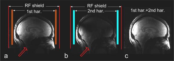
Figure 6 shows the combined images in the sagittal plane from all the first harmonic elements, all the second harmonic elements and their combination. The sum-of-squares combined images are shown with the same signal intensity scale and without using any image processing method. As expected, the image from first harmonic elements (Figure 6a) had a high signal intensity located at the center of the coil, but the signal was weak at the lower part of the brain, limiting the imaging capability in the brain stem, cerebellum and upper spinal cord. In Figure 5b, the MR signals from the second harmonic elements were weak at the center but strong at the two ends of the transceiver array, which enabled a better imaging in the lower part of the brain. The combination image in Figure 6c shows good coverage of the whole brain. With the help of the second harmonic coil elements, the imaging coverage of this array has increased compared to the array having only primary resonance elements.
Fig. 6.
Human brain images at sagittal plane from all the 1st harmonic coil elements (a), all the 2nd harmonic coil elements (b) and their combinatio n (c). 2nd harmonic elements helped to image the lower part of the brain. Parameters used were: TE/TR 6.9ms/100ms, FOV 24cm × 24cm, slice thickness 3mm, Matrix 256 × 256, NEX = 4, flip angle = 200, matrix size = 256 × 256.
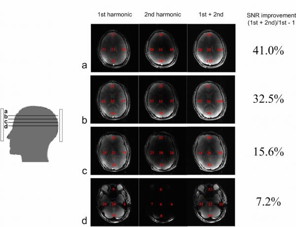
Figure 7 shows the combined images in different axial planes from all the first harmonic elements, all the second harmonic elements and their combination. Local SNR at four periphery areas and the center of the brain were calculated and marked in the images. The combined axial images from second harmonic elements show high signal intensity at the periphery. But the signal intensity drops fast with depth. As expected, the signal intensities from the second harmonic coil elements also varied across different axial planes. In this case, the higher the images are towards the top of the brain, the better the SNR achieved. The overall SNR gain (SNR from entire 16 elements v.s. SNR from 8 primary harmonic elements) also illustrates this tendency. In Figure 6a, 41% SNR gain was achieved with the help of the second harmonic coil elements. Even at the center of the coil array, a SNR gain of 7.2% was still achieved (Figure 6d).
Fig. 7.
Combined human brain images with first and second harmonic coil elements and all coil elements at axial planes from (a) to (d). Ave raged regional SNR measurements are shown in the right column. The percentage of SNR improvement represents the SNR contribution from second harmonic coil elements. More SNR contribution comes from second harmonic coil elements in slices closer to the top of the human brain.
A GRAPPA reconstruction algorithm was employed in evaluation of the parallel imaging performance of the proposed transceiver array with the raw data acquired from healthy volunteers at 7T. The accelerated images with a reduction factor from 2 to 5 together with the images without acceleration are reconstructed and shown in Figure 8. When the imaging speed reaches ~5-fold faster than the regular imaging, the image still had an acceptable quality. In the reconstruction, 10 auto-calibration signal (ACS) lines were used for each reduction rate.
Fig. 8.
Images reconstructed using GRAPPA with different reduction factors R from 2 to 5, demonstrating the parallel imaging performance of the proposed 16-channel transceiver array at 7T. ACS lines = 10.
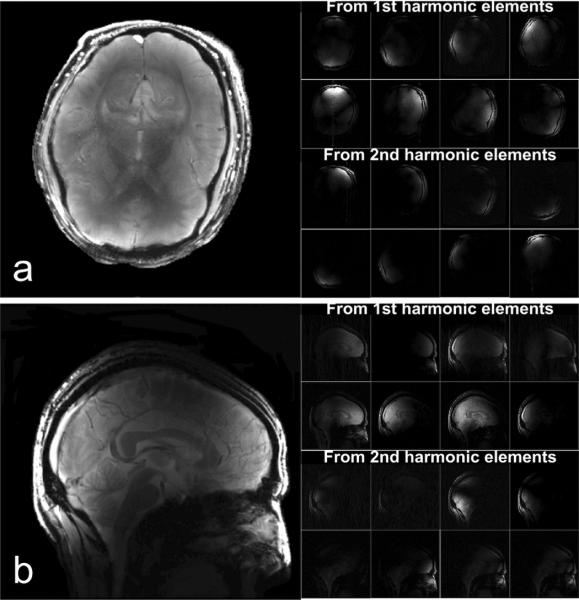
Individual images from each coil element and their combinations are shown in Figure 9. The individual images from the first harmonic coil elements are listed in the first two rows and images from second harmonic coil elements are listed in the following two rows. The combined images in Figure 9 were corrected from the original images for signal intensity variations. Images were first segmented by using a custom-custom-made software based on a mathematic morphology algorithm [38] to minimize the background noise and then corrected to enhance the signal intensity at the center of the brain. The parallel imaging g-factors at various reduction factors were calculated and the results were shown in Table 1. Based on the g-factor plots illustrated in Figure 10, the proposed design of using mixed primary and second harmonic resonators, compared with the conventional design using only primary resonant elements, yielded improved g-factors and thus parallel imaging performance, particularly at higher reduction rate.
Fig. 9.
GRE data set acquired with the GE 7T scanner. (a) shows combined GRE images and sub-images from each coil element in axial plane with 20° flip Angle, TE/TR 6.9ms/100ms, 24cm × 24cm FOV, 256 × 256 matrix, 3mm slice thickness, NEX 1. (b) shows combined images acquired using the same GRE sequence but with 4 NEX and corrected signal intensity.
TABLE I.
Average g-factors at different reduction factors calculated for a primary 8 channel array (8ch 1st) and a 16-channel mixed primary and 2nd harmonic resonator array (16ch mix). The calculation was based on human head images acquired from each resonant element at sagittal plane. With an easy upgrade of a conventional 8 channel primary microstrip array, the g-factor was significantly improved, thus the improved parallel imaging performance would be expected.
| Reduction Factor (R) | 2 | 3 | 4 | 5 | 6 | 7 | 8 | 9 | 10 | 11 | 12 | 13 | 14 | 15 | 16 |
|---|---|---|---|---|---|---|---|---|---|---|---|---|---|---|---|
| 8ch 1st | 1.1 | 1.22 | 1.45 | 1.99 | 3.54 | 8.18 | 109.82 | * | * | * | * | * | * | * | * |
| 16ch mix | 1.03 | 1.06 | 1.12 | 1.19 | 1.29 | 1.43 | 1.67 | 2.03 | 2.66 | 3.58 | 4.77 | 7.44 | 10.47 | 17.66 | 1096 |
custom-made software based on a mathematic morphology
Fig. 10.
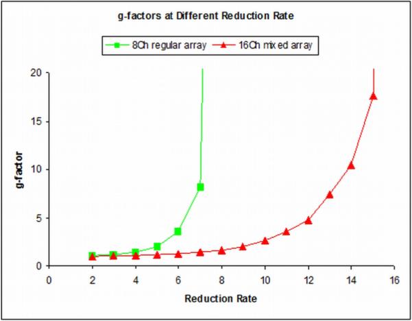
g-factors at different reduction rate calculated based on the 7T head imaging acquired using the 8-channel primary resonator array and the 16-channel mixed array. With the convenient channel upgrade using the proposed mixed harmonic method, the parallel imaging performance of the 8-channel coil array is significantly improved.
IV. Discussion and Conclusion
A transceiver array design technique using the mixed harmonic transmission line resonators is introduced for high field parallel imaging applications in humans. This technology has been successfully implemented by designing and testing multi-channel head-sized transceiver arrays for 7T imaging, demonstrating the feasibility of the proposed design technique for human MR imaging. The transceiver arrays based on this technique provide improved decoupling performance, enlarged imaging coverage and excellent parallel imaging performance due to the reduced g-factor. The unique decoupling performance makes this mixed harmonic technique particularly useful in designing massively parallel arrays where the electromagnetic decoupling among elements becomes much more problematic due to dramatically increased mutual inductance in densely placed resonant elements. With the proposed technique, the element number or channel number of a RF coil array made of conventional first harmonic resonators can be readily doubled without adding additional decoupling treatment by alternately inserting the second harmonic resonators in the coil array, leading to a much faster imaging coil array.
The filling factor of any type of RF coil is crucial to MR SNR and signal excitation efficiency. Therefore, for those MR applications where the SNR is critical, size scalable RF coils are usually desirable so that the RF coils can best fit the different subjects. This is especially important for the parallel imaging coil array which is usually comprised of a set of surface coils, because the B1 field of surface coils has an extremely strong gradient and their MR SNR is therefore very sensitive to the distance between the coil and imaging subject. The proposed technique which requires no dedicated decoupling components or networks to electromagnetically decouple the resonant elements, and thus no physical connections among resonant elements would significantly reduce the design challenges in realizing the size scalable feature for high field transceiver arrays in practice. This technique directly results in a successful design for a flexible transceiver array targeting different body parts for human parallel imaging at the ultrahigh field of 7T [34]. Large coils usually have a large imaging coverage. However it is challenging to design large-size coils for the high frequency operation. One of the reasons is that large-size coils have increased inductance and parasitic capacitance which is a factor in decreasing the resonant frequency of RF coils. By using the proposed design of alternately placed first and second harmonic resonators, imaging coverage of a head transceiver array can be improved without increasing the coil length, so that lower brain regions, such as the cerebellum, brain stem and upper spinal cord can be observed.
Due to the lack of multiple transmit channels, only two transmit channel could be driven at a time. However, tipping the spins through a specified angle over any significant volume depends upon the constructive interference of fields from multiple transmit elements, and cannot straightforwardly be achieved by separately driving pairs of elements in a temporal sequence. Thus, the resulting images shown in this work might be different from those acquired using all the transmit channels simultaneously.
With the capability of independent amplitude and phase control on each coil element, manipulation of B1 excitation field (i.e. B1+) and selective excitation are able to be performed and investigated by using the prototype 16-channel transceiver array in human subjects at the ultrahigh field of 7T. In addition, the operation method of this transceiver array is flexible. As a choice of operation methods, the proposed transceiver array can be used in a way that, for example, the 8 first harmonic elements are transmitters while entire 16 first and second harmonic elements are receivers. This competence of a high frequency transceiver array would be advantageous and valuable, especially for MR systems in which the transmit channel number is limited.
Acknowledgments
This work was supported in part by the national Institutes of Health (NIH) under grant EB004453, Grant EB008699, Grant EB007588-03S1, and UL1 RR0241310-01, and in part by a QB3 Research Award
References
- [1].Adriany G, Van de Moortele PF, Wiesinger F, Moeller S, Strupp JP, Andersen P, Snyder C, Zhang X, Chen W, Pruessmann KP, Boesiger P, Vaughan T, Ugurbil K. Transmit and receive transmission line arrays for 7 Tesla parallel imaging. Magn Reson Med. 2005;53:434–45. doi: 10.1002/mrm.20321. [DOI] [PubMed] [Google Scholar]
- [2].Zhang X, Burr AR, Zhu X, Adriany G, Ugurbil K, Chen W. A Dual-tuned Microstrip Volume Coil Array for Human Head parallel 1H/31P MRI/MRS at 7T. The 11th Annual Meeting of ISMRM; Miami, Florida, USA. 2005. [Google Scholar]
- [3].Wu B, Wang C, Kelley DA, Xu D, Vigneron DB, Nelson SJ, Zhang X. Shielded microstrip array for 7T human MR imaging. IEEE Trans Med Imaging. 2010;29:179–84. doi: 10.1109/TMI.2009.2033597. [DOI] [PMC free article] [PubMed] [Google Scholar]
- [4].Vaughan T, DelaBarre L, Snyder C, Tian J, Akgun C, Shrivastava D, Liu W, Olson C, Adriany G, Strupp J, Andersen P, Gopinath A, van de Moortele PF, Garwood M, Ugurbil K. 9.4T human MRI: preliminary results. Magn Reson Med. 2006;56:1274–82. doi: 10.1002/mrm.21073. [DOI] [PMC free article] [PubMed] [Google Scholar]
- [5].Xu D, King KF, Zhu Y, McKinnon GC, Liang ZP. Designing multichannel, multidimensional, arbitrary flip angle RF pulses using an optimal control approach. Magn Reson Med. 2008;59:547–60. doi: 10.1002/mrm.21485. [DOI] [PMC free article] [PubMed] [Google Scholar]
- [6].Ma C, Xu D, King KF, Liang ZP. Perturbation analysis of the effects of B1+ errors on parallel excitation in MRI. Conf Proc IEEE Eng Med Biol Soc. 2009;2009:4064–6. doi: 10.1109/IEMBS.2009.5333196. [DOI] [PubMed] [Google Scholar]
- [7].Zhu Y. Parallel excitation with an array of transmit coils. Magn Reson Med. 2004;51:775–84. doi: 10.1002/mrm.20011. [DOI] [PubMed] [Google Scholar]
- [8].Zhang X, Chen W. B1 shimming using a volume coil at high fields. The 13th Annual Meeting of ISMRM; Miami, Florida, USA. 2005. [Google Scholar]
- [9].Yang QX, Mao W, Wang J, Smith MB, Lei H, Zhang X, Ugurbil K, Chen W. Manipulation of image intensity distribution at 7.0 T: passive RF shimming and focusing with dielectric materials. J Magn Reson Imaging. 2006;24:197–202. doi: 10.1002/jmri.20603. [DOI] [PubMed] [Google Scholar]
- [10].Wu B, Wang C, Krug R, Kelley DA, Xu D, Pang Y, Banerjee S, Vigneron DB, Nelson SJ, Majumdar S, Zhang X. 7T human spine imaging arrays with adjustable inductive decoupling. IEEE Trans Biomed Eng. 2010;57:397–403. doi: 10.1109/TBME.2009.2030170. [DOI] [PMC free article] [PubMed] [Google Scholar]
- [11].Lee RF, Giaquinto RO, Hardy CJ. Coupling and decoupling theory and its application to the MRI phased array. Magn Reson Med. 2002;48:203–13. doi: 10.1002/mrm.10186. [DOI] [PubMed] [Google Scholar]
- [12].Zhang X, Webb A. Design of a capacitively decoupled transmit/receive NMR phased array for high field microscopy at 14.1T. J Magn Reson. 2004;170:149–55. doi: 10.1016/j.jmr.2004.05.004. [DOI] [PubMed] [Google Scholar]
- [13].Li Y, Xie Z, Pang Y, Vigneron D, Zhang X. ICE decoupling technique for RF coil array designs. Medical Physics. 2011;38:4086–4093. doi: 10.1118/1.3598112. [DOI] [PMC free article] [PubMed] [Google Scholar]
- [14].Ibrahim TS, Kangarlu A, Chakeress DW. Design and performance issues of RF coils utilized in ultra high field MRI: experimental and numerical evaluations. IEEE Trans Biomed Eng. 2005;52:1278–84. doi: 10.1109/TBME.2005.847564. [DOI] [PubMed] [Google Scholar]
- [15].Wiggins GC, Triantafyllou C, Potthast A, Reykowski A, Nittka M, Wald LL. 32-channel 3 Tesla receive-only phased-array head coil with soccer-ball element geometry. Magn Reson Med. 2006;56:216–23. doi: 10.1002/mrm.20925. [DOI] [PubMed] [Google Scholar]
- [16].Son JB, Ji JX, McDougall MP, Wright SM. Adaptive SENSE reconstruction for parallel imaging with massive array coils. Conf Proc IEEE Eng Med Biol Soc. 2004;2:1064–7. doi: 10.1109/IEMBS.2004.1403347. [DOI] [PubMed] [Google Scholar]
- [17].Roemer PB, Edelstein WA, Hayes CE, Souza SP, Mueller OM. The NMR phased array. Magn Reson Med. 1990;16:192–225. doi: 10.1002/mrm.1910160203. [DOI] [PubMed] [Google Scholar]
- [18].Jevtic J. Ladder network for capacitive decoupling in phased-array coils. The 9th Annual Meeting of ISMRM; Glasgow, Scotland. 2001. [Google Scholar]
- [19].Wang J. A novel method to reduce the signal coupling of surface coils for MRI. The 4th Annual Meeting of ISMRM; New York, New York, USA: 1996. [Google Scholar]
- [20].Sutton BP, Ciobanu L, Zhang X, Webb A. Parallel imaging for NMR microscopy at 14.1 Tesla. Magn Reson Med. 2005;54:9–13. doi: 10.1002/mrm.20531. [DOI] [PubMed] [Google Scholar]
- [21].Lee RF, Westgate CR, Weiss RG, Newman DC, Bottomley PA. Planar strip array (PSA) for MRI. Magn Reson Med. 2001;45:673–83. doi: 10.1002/mrm.1090. [DOI] [PMC free article] [PubMed] [Google Scholar]
- [22].Zhang X. Biomedical engineering, vol. Ph.D. University of Minnesota; Minneapolis: 2002. Novel radio frequency resonators for in vivo magnetic resonance imaging and spectroscopy at very high magnetic fields; p. 259. [Google Scholar]
- [23].Zhang X, Ugurbil K, Sainati R, Chen W. An inverted-microstrip resonator for human head proton MR imaging at 7 tesla. IEEE Trans Biomed Eng. 2005;52:495–504. doi: 10.1109/TBME.2004.842968. [DOI] [PubMed] [Google Scholar]
- [24].Wu B, Zhang X, Qu P, Shen GX. Capacitively decoupled tunable loop microstrip (TLM) array at 7 T. Magn Reson Imaging. 2007;25:418–24. doi: 10.1016/j.mri.2006.09.031. [DOI] [PubMed] [Google Scholar]
- [25].Wu B, Zhang X, Qu P, Shen GX. Design of an inductively decoupled microstrip array at 9.4 T. J Magn Reson. 2006;182:126–32. doi: 10.1016/j.jmr.2006.04.013. [DOI] [PubMed] [Google Scholar]
- [26].Zhang X, Zhu XH, Chen W. Higher-order harmonic transmission-line RF coil design for MR applications. Magn Reson Med. 2005;53:1234–9. doi: 10.1002/mrm.20462. [DOI] [PubMed] [Google Scholar]
- [27].Wu B, Wang C, Xie Z, Zhang X. 16-channel microstrip array using 1st and 2nd harmonics for parallel imaging at 7T. The 16th Annual Meeting of ISMRM; Toronto, Canada. 2008. [Google Scholar]
- [28].Pang Y, Zhang X, Xie Z, Wang C, Vigneron D. Common-mode differential-mode (CMDM) method for double-nuclear MR signal excitation and reception at ultrahigh fields. IEEE Trans Med Imaging. 2011 Jun 20; doi: 10.1109/TMI.2011.2160192. Epub ahead of print. [DOI] [PMC free article] [PubMed] [Google Scholar]
- [29].Pang Y, Xie Z, Li Y, Xu D, Vigneron D, Zhang X. Resonant mode reduction in radiofrequency volume coils for ultrahigh field magnetic resonance imaging. Materials. 2011;4:1333–1344. doi: 10.3390/ma4081333. [DOI] [PMC free article] [PubMed] [Google Scholar]
- [30].Zhang X, Ugurbil K, Chen W. Microstrip RF surface coil design for extremely high-field MRI and spectroscopy. Magn Reson Med. 2001;46:443–50. doi: 10.1002/mrm.1212. [DOI] [PubMed] [Google Scholar]
- [31].Zhang X, Ugurbil K, Chen W. A microstrip transmission line volume coil for human head MR imaging at 4T. J Magn Reson. 2003;161:242–51. doi: 10.1016/s1090-7807(03)00004-1. [DOI] [PubMed] [Google Scholar]
- [32].Chang K, Hsieh L-H. Microwave Ring Circuits and Related Structures. 2nd ed ed. J. Wiley; Hoboken, NJ: 2004. [Google Scholar]
- [33].Kumar S. Electronically Tunable Ring Resonator Microstrip and Suspended-Substrate Filters. Electronics Letters. 1991;27:521–523. [Google Scholar]
- [34].Wu B, Wang C, Krug R, Kelley D, Pang Y, Xu D, Majumdar S, Nelson S, Vigneron D, Zhang X. Multi-purpose Flexible Transceiver Array at 7T. The 17th Annual Meeting of ISMRM; Honolulu, HI, USA. 2009. [Google Scholar]
- [35].NEMA standard publication MS 1-2008. National Electrical manufacturers Association. 2008 [Google Scholar]
- [36].Qu P, Shen GX, Wang C, Wu B, Yuan J. Tailored utilization of acquired k-space points for GRAPPA reconstruction. J Magn Reson. 2005;174:60–7. doi: 10.1016/j.jmr.2005.01.015. [DOI] [PubMed] [Google Scholar]
- [37].Lin F. http://www.nmr.mgh.harvard.edu/~fhlin/tool_sense.htm.
- [38].Cline HE, Thedens DR, Irarrazaval P, Meyer CH, Hu BS, Nishimura DG, Ludke S. 3D MR coronary artery segmentation. Magn Reson Med. 1998;40:697–702. doi: 10.1002/mrm.1910400509. [DOI] [PubMed] [Google Scholar]


