Abstract
Objectives
The aim of this study was to compare two methods of measuring mandibular asymmetry. The first method uses mirroring of the mandible in the midsagittal plane; the second uses mirroring of the mandible and registration on the cranial base.
Methods
Surface models were constructed from cone beam CT (CBCT) scans of 50 patients with asymmetry. For the first approach, a midsagittal plane was defined for each patient as the plane passing through nasion, anterior nasal spine and basion. Mirrors for both halves of the mandible were created. The second approach consisted of mirroring the image volume by flipping the left and right sides and then registering the mirrored image onto the cranial base using a mutual information maximization method. Surface distances between hemimandibles and mirrors were calculated for nine regions.
Results
There was no statistically significant difference between the mean surface distance measurements obtained with the two approaches and when comparing both halves in most areas.
Conclusion
Both mirroring techniques provided similar quantification of mandibular asymmetry in this cohort.
Keywords: cone beam computed tomography, mandible, asymmetry, surface models, mirroring
Introduction
Facial asymmetry is common and sometimes poses a challenge in craniofacial diagnosis and treatment planning.1,2 It is aetiologically and pathologically heterogeneous and may be localized or generalized. This wide variability in the aetiology and in the presentation of the disease necessitates that the management of those patients be a multifactorial stepwise decision making process. Proper assessment and quantification of the differences between the right and the left sides are crucial for diagnosis, treatment planning and follow up. Conventional posterio-anterior cephalometric radiographs used in orthodontic practice to assess asymmetry have inherent limitations as a result of superimposition, magnification and distortion.
Three-dimensional (3D) imaging and associated image analysis methods developed recently carry a potential for development in this field. The use of relatively low-dose cone beam CT (CBCT) scanners in dental practices facilitates the examination of anatomical structures in a multiplanar view. It also provides a rich soil for the application of different image analysis techniques to further extract diagnostic information from available volumes. Creation of 3D virtual surface models from CBCT volumes, registration of those models and measurements of the surface distances between different models is a well documented approach used to study growth, treatment changes and the stability of those changes.3-7
Various approaches have been described in the literature in an attempt to use 3D imaging for the detection and quantification of craniofacial asymmetry.8-10 However, most of these techniques depend on landmark identification and manual identification of a straight “midsagittal plane”, both of which proved to be extremely challenging and operator-dependent.
In 2000, a method to automatically define the midsagittal plane of the brain in two-dimensional cross-sectional slices was presented.11 However, definition of the midsagittal plane in the maxillofacial area remains a challenge because the plane is a curved surface in some faces with chin deviation. In 2004, an alternative method for determining a symmetry plane was presented, using mirroring of the mandible in any arbitrary plane with rigid registration of the mirrored mandible to the original image.12 However, this procedure did not take into consideration the mandibular morphological relationships with the maxilla and the cranial base. A modification of this approach that first mirrors the image and then registers on the cranial base can provide information on the entire facial structure rather than just the mandible.7
The aim of this study was to compare the degree of mandibular asymmetry, as obtained by surface distance measurement, using mirroring of the mandible in the “midsagittal plane” vs mirroring of the mandible followed by registration on the cranial base.
Materials and methods
Following a protocol approved by the institutional review board for research involving human subjects, 50 patients with clinically detectable asymmetry served as the cohort of this study. Clinical asymmetry was defined as more than 2 mm of chin deviation or the presence of cant of the occlusal plan before the start of their orthodontic treatment. CBCT scans of all patients were obtained using NewTom 3G cone beam scanner (Aperio Services, Sarasota, FL). The 12 inch field of view producing 0.5 mm isotropic voxel sizes was used for acquiring the image volume. 3D surface models were constructed from the CBCT volumes using segmentation tools of the Insight SNAP software (http://www.itksnap.org/pmwiki/pmwiki.php).13 Following segmentation, a 3D graphical rendering of the volumetric object allowed navigation between voxels in the volumetric image and the 3D graphics with zooming, rotating and panning.
Midsagittal plane approach
Nasion (Na), anterior nasal spine (ANS) and basion (Ba) were manually defined for each patient by one observer. The midsagittal plane was defined as the plane passing through those three landmarks. The resultant midsagittal plane was used to create mirrors for both halves of the mandible.
Na, ANS, Ba, the midsagittal plane and the degree of asymmetry were determined 5 times on 22 randomly selected patients from the cohort. Differences between repeated assessments of asymmetry served as a measure of reproducibility of midsagittal plane identification.
Registration-based approach
Each model was mirrored on an arbitrary plane. The mirroring is done by arbitrarily converting the image orientation from right–left, anterior–posterior and inferior–superior to left–right, anterior–posterior and inferior–superior with a proprietary software called Imconverter tool (University of North Carolina, Chapel Hill, NC). The original and the arbitrarily mirrored images were then registered on the cranial base. The registration was accomplished using IMAGINE software (National Institutes of Health, Bethesda, MD) following a voxel-based registration method. This method utilizes maximization of mutual information to avoid observer-dependent techniques. After the software masks the maxillary and mandibular structures, it compares the grey level intensity of each voxel in the cranial base to register the two CBCT images. The rotation and translation parameters that are used to register the two greyscale images are also applied to register the 3D surface models.
CMFApp software (University of North Carolina, Chapel Hill, NC)14-17 was used to display the superimposed images with the two approaches: (1) original image superimposed on the image mirrored on the midsagittal plane; (2) original image superimposed on the image that was arbitrary mirrored and then registered to the original image.
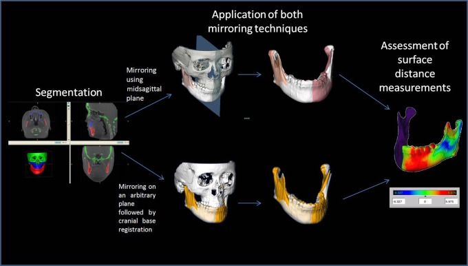
Surface distances were compared between the resultant mirrors from both approaches and the original mandible. The average surface distances of the right and left side were calculated for nine anatomical regions of interest (ROI): the lateral pole; medial pole; anterior and posterior surfaces of both condyles; lateral surface of the rami and corpora of the mandible; inferior and posterior surfaces of the mandible; and anterior surface of the symphysis. Computation of surface distances was based on iterative closest point algorithm. The 95th percentile surface distance measurement of each ROI was considered as a measurement of asymmetry at that location. The measures of surface distances were complemented by visualization of the 3D colour-coded maps (Figure 1).
Figure 1.
Assessment of asymmetry following two different mirroring methods
Paired t-tests were used to assess statistical differences between the surface distance measurements obtained by the two approaches for each anatomical location. They were also used to test for differences between the measurements obtained for the right and the left sides for each approach. The Cochran–Mantel–Haenszel test was used to test for the effect of the degree of asymmetry on the difference detected between the two approaches (α = 0.05).
Results
The variability in surface distance measurements obtained from five repeated assessments of the midsagittal plane for each subject ranged from 0 mm to 1.63 mm with a mean of 0.42 mm and a standard deviation of 0.18 mm. Only five patients had a discrepancy larger than 1 mm. The paired t-tests showed no statistically significant difference in quantification of asymmetry among the five measurement sets (P > 0.1 for all paired comparisons and P = 0.44 when pooled measurements were tested together).
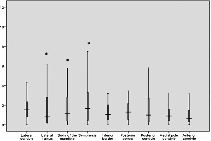
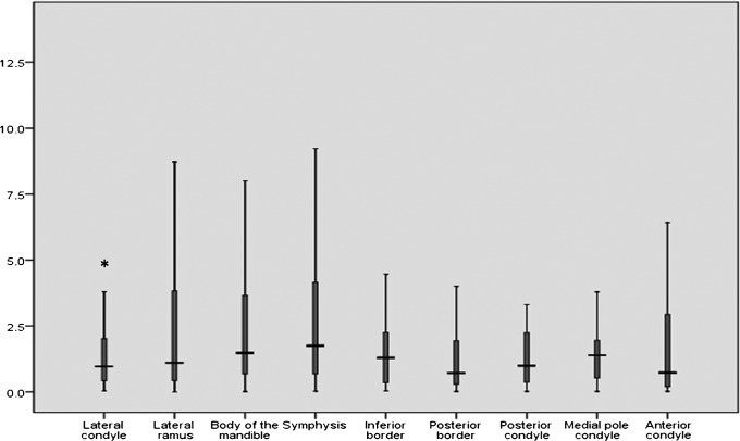
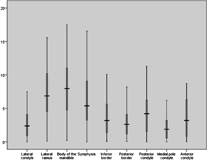
Of the 18 anatomical areas measured, the mandibular ramus (P = 0.04), body (P = 0.01), symphysis (P = 0.005) at the right side and the lateral pole of the condyle at the left side (P = 0.02) showed statistically significant differences in the mean surface distance between the two approaches. The differences in the mean surface distances ranged from 0.2 mm to 1.5 mm (Table 1 and Figures 2 and 3).
Table 1. Descriptive statistics for the absolute difference in surface distance measurements between the two methods at the different anatomical locations.
| n | Mean | Standard deviation | |
| Lateral pole of the left condyle | 47 | 1.73 | 1.36 |
| Left ramus | 50 | 2.00 | 2.50 |
| Left body | 50 | 2.14 | 2.57 |
| Left symphysis | 50 | 2.35 | 2.27 |
| Left inferior border | 50 | 1.70 | 1.94 |
| Left posterior border | 50 | 1.71 | 1.65 |
| Posterior surface of the left condyle | 47 | 1.53 | 1.50 |
| Medial surface of the left condyle | 47 | 1.41 | 1.79 |
| Anterior surface of the left condyle | 47 | 1.35 | 1.77 |
| Lateral pole of the right condyle | 48 | 1.84 | 2.18 |
| Right ramus | 50 | 2.54 | 3.08 |
| Right body | 50 | 2.82 | 3.21 |
| Right symphysis | 50 | 2.58 | 2.34 |
| Right inferior border | 50 | 1.42 | 1.57 |
| Right posterior border | 50 | 1.48 | 1.37 |
| Posterior surface of the right condyle | 48 | 1.65 | 1.90 |
| Medial pole of the right condyle | 48 | 1.62 | 1.37 |
| Anterior surface of the right condyle | 48 | 1.59 | 1.87 |
Figure 2.
A box plot demonstrating the mean of the absolute difference in surface distance measurements (mm) using both mirroring methods on each region of interest on the left side (* indicates statistical significance)
Figure 3.
A box plot demonstrating the mean of the absolute difference in surface distance measurements (mm) using both mirroring methods on each region of interest on the right side (* indicates statistical significance)
A positive correlation between asymmetry measurements and the discrepancy between the methods was observed at the right inferior border (P = 0.048), left posterior border (P = 0.04) and medial pole of the left condyle (P = 0.03).
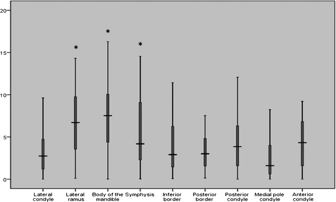
There was no statistically significant difference in the mean of surface distance measurements between the left and the right side for all locations using the registered mirror. However, a significant difference was observed in the ramus (P = 0.02), the body of the mandible (P = 0.03) and the symphysis area (P = 0.04) when mirroring with the midsagittal plane was used (Figures 4 and 5).
Figure 4.
A box plot showing the mean of the absolute difference in surface distance measurements (mm) of the left and right sides of the mandible using mirroring on the midsagittal plan (* indicates statistical significance)
Figure 5.
A box plot showing the mean of the absolute difference in surface distance measurements (mm) of the left and right sides of the mandible using using arbitrary mirroring followed by registration on cranial base
Discussion
Although cephalometric radiography has been and will probably continue to be the routine radiographic examination for any patient seeking orthodontic/orthognathic treatment, the “inappropriateness of conventional cephalometrics” was recognized as early as 1979.18 Those inadequacies are further accentuated when challenged with bilateral differences in the anatomy. 3D cephalometry has the potential advantage of being able to better detect and localize existing asymmetries. However, quantification of asymmetries using 3D cephalometry heavily depends on the operator's understanding of 3D landmark definition and the ability to reproducibly define those landmarks.8,9 The use of surface distance measurements between the two halves of the mandible that served as our asymmetry quantification outcome overcomes the need to depend on points as surrogates for real structures.
In this cohort, the use of either mirroring approach (midsagittal plane and registration-based approach) provided similar results in most areas. Most of the discrepancies in surface distance measurements were located on the lateral surface of the mandible, which suggests that the mediolateral direction is most sensitive to mirroring.
It can be hypothesized that there should be no difference in the absolute surface distance measurements based on whether the right or the left side of the mandible is being mirrored. That was true when mirroring using an arbitrary plane with registration on the cranial base, but the use of a midsagittal plane mirroring produced inconsistencies at some locations. It follows that most of those locations were the same ones that showed discrepancies between the two approaches.
The differences between the two mirroring approaches, although statistically insignificant, tended to increase with more severe asymmetries. Application of both approaches to an exclusive cohort of patients with severe asymmetries may further characterize this trend in terms of location and the cut-off point of maximal difference.
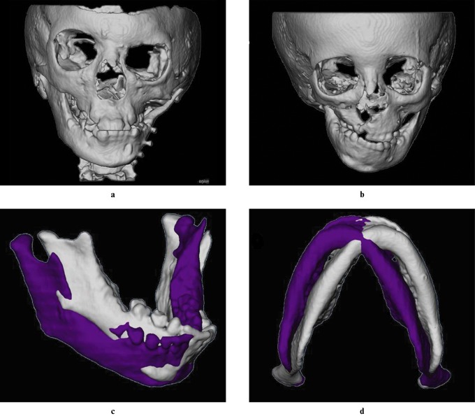
Neither approach could be applied indiscriminately to any patient. Mirroring using the midsagittal plane is difficult for patients suffering from conditions that interfere with the midline position of the points used to define the midsagittal plane, i.e.cleft palate patients. On the other hand, registration on the cranial base in patients with asymmetries involving the cranial base would also result in suboptimal results.
Applying both mirroring approaches to patients with rudimentary condyles, severe cants or a rotated mandible would result in important discrepancies between the mirrored image and the original. This complicates the interpretation of the surface distances obtained at a specified location. The measured distance would not represent the difference between corresponding anatomical locations, but rather the minimal difference between the models as computed by the iterative closest point algorithm used by CMFApp software (Figure 6).
Figure 6.
Examples of patients with challenging asymmetries for quantification. Asymmetric cranial base (a) and cleft palate (b) would interfere with both mirroring protocols. Severe cant (c) and rotation (d) is hard to deal with using iterative closest point algorithm
In conclusion, both mirroring using a midsagittal plane and using a registration-based approach provided similar quantification of mandibular asymmetry for most areas. One of these approaches is considered an alternative to the other when certain structural features of the patient impede the use of either approach.
Shape correspondence, a technology that allows measuring of the surface distance between an area on one model to the same corresponding area in the other model regardless of the alignment of those models, is currently being investigated as a promising alternative to overcome the shortcomings of the iterative closest point algorithm in situations of important discrepancy.
Acknowledgments
Supported by NIDCR DE017727 and DE018962.
References
- 1.Severt TR, Proffit WR. The prevalence of facial asymmetry in the dentofacial deformities population at the University of North Carolina. Int J Adult Orthodon Orthognath Surg 1997;12:171–176 [PubMed] [Google Scholar]
- 2.Proffit WR, Fields HW, Jr, Moray LJ. Prevalence of malocclusion and orthodontic treatment need in the United States: Estimates from the NHANES III survey. Int J Adult Orthodon Orthognath Surg 1998;13:97–106 [PubMed] [Google Scholar]
- 3.Cevidanes LH, Bailey LJ, Tucker GR, Jr, Styner MA, Mol A, Phillips CL, et al. Superimposition of 3D cone-beam CT models of orthognathic surgery patients. Dentomaxillofac Radiol 2005;34:369–375 [DOI] [PMC free article] [PubMed] [Google Scholar]
- 4.Cevidanes LH, Bailey LJ, Tucker SF, Styner MA, Mol A, Phillips CL, et al. Three-dimensional cone-beam computed tomography for assessment of mandibular changes after orthognathic surgery. Am J Orthod Dentofacial Orthop 2007;131:44–50 [DOI] [PMC free article] [PubMed] [Google Scholar]
- 5.Cevidanes LH, Franco AA, Gerig G, Proffit WR, Slice DE, Enlow DH, et al. Comparison of relative mandibular growth vectors with high-resolution 3-dimensional imaging. Am J Orthod Dentofacial Orthop 2005;128:27–34 [DOI] [PubMed] [Google Scholar]
- 6.Cevidanes LH, Franco AA, Gerig G, Proffit WR, Slice DE, Enlow DH, et al. Assessment of mandibular growth and response to orthopedic treatment with 3-dimensional magnetic resonance images. Am J Orthod Dentofacial Orthop 2005;128:16–26 [DOI] [PubMed] [Google Scholar]
- 7.Cevidanes LH, Styner MA, Proffit WR. Image analysis and superimposition of 3-dimensional cone-beam computed tomography models. Am J Orthod Dentofacial Orthop 2006;129:611–618 [DOI] [PMC free article] [PubMed] [Google Scholar]
- 8.Katsumata A, Fujishita M, Maeda M, Ariji Y, Ariji E, Langlais RP. 3D-CT evaluation of facial asymmetry. Oral Surg Oral Med Oral Pathol Oral Radiol Endod 2005;99:212–220 [DOI] [PubMed] [Google Scholar]
- 9.Maeda M, Katsumata A, Ariji Y, Muramatsu A, Yoshida K, Goto S, et al. 3D-CT evaluation of facial asymmetry in patients with maxillofacial deformities. Oral Surg Oral Med Oral Pathol Oral Radiol Endod 2006;102:382–390 [DOI] [PubMed] [Google Scholar]
- 10.Park SH, Yu HS, Kim KD, Lee KJ, Baik HS. A proposal for a new analysis of craniofacial morphology by 3-dimensional computed tomography. Am J Orthod Dentofacial Orthop 2006;129:600.e23,600.e34 [DOI] [PubMed] [Google Scholar]
- 11.Prima S, Ourselin S, Ayache N. Computation of the mid-sagittal plane in 3D images of the brain. Computer Vision ECCV 2000:685–701 [Google Scholar]
- 12.Glerup N. Asymmetry measures in medical image analysis [dissertation]. Department of Innovation IT, University of Copenhagen; 2005. April 29 [Google Scholar]
- 13.Yushkevich PA, Piven J, Hazlett HC, Smith RG, Ho S, Gee JC, et al. User-guided 3D active contour segmentation of anatomical structures: Significantly improved efficiency and reliability. NeuroImage 2006;31:1116–1128 [DOI] [PubMed] [Google Scholar]
- 14.Chapuis J. Computer-aided cranio-maxillofacial surgery [dissertation]. Switszerland: University of Bern, 2006 [Google Scholar]
- 15.Chapuis J, Ryan P, Blaeuer M, Langlotz F, Hallermann W, Schramm A, et al. A new approach for 3D computer-assisted orthognathic surgery—first clinical case. Int Congr Ser 2005;1281:1217–1222 [Google Scholar]
- 16.De Momi EF, Chapuis JF, Pappas IF, Ferrigno GF, Hallermann WF, Schramm AF, et al. Automatic extraction of the mid-facial plane for cranio-maxillofacial surgery planning. Int J Oral Maxillofac Surg 2006;35:636–642 [DOI] [PubMed] [Google Scholar]
- 17.Chapuis J, Rudolph T, Borgesson B, De Momi E, Pappas I, Hallermann W, et al. 3D surgical planning and navigation for CMF surgery. SPIE Medical imaging: San Diego, California, USA, 2004 [Google Scholar]
- 18.Moyers RE, Bookstein FL. The inappropriateness of conventional cephalometrics. Am J Orthod 1979;75:599–561 [DOI] [PubMed] [Google Scholar]


