Summary
The catheter kickback phenomenon often occurs in the last stage of coil packing for cerebral aneurysms. This behavior is considered the result of either a lack of space in the sac or a stiff detaching zone. In order to clarify its mechanism, focused stretch-resistance (SR) coil simulation models were tested.
Various commercially available SR coils were inserted into a cylinder or an aneurismal sac made from a silicone tube with a smaller than prescribed diameter. A magnified SR coil model (straight type) of fishing line was created for simulation. Numerical analysis for the changes in coil behavior were verified.
All SR coils showed hardening and straightening at the last few millimeters, resulting in catheter kickback. In a magnified coil experiment, straightening was also realized when folding into a narrow cylinder.
The SR line coursed in the canal of the first loops and shifted to the outside in the middle portion. Gaps among first coil pitches were enlarged on after insertion into the narrower space. Shortage of the SR line was calculated to reach a maximum of 32%.
The straightening phenomenon is due to SR line shortening and subsequent condensation of pitches of the first loops at the coil end. Coil tail flexibility was lost, and the coil behaved as a stiff wire.
Straightening is an important factor in the kickback phenomenon. Shorter final SR coils should be selected, and coil designs should be improved.
Keywords: aneurysm, coil embolizaton, stretch resistance, kickback, straightening
Introduction
Treatment of cerebral aneurysms with coil embolization is gradually growing due to the efficacy of the technique that has been clarified in various randomized control studies. Additionally, the development of various types of coils, including extremely soft coils, has enabled adequate flaming and dense packing for the complicated shape of aneurysms. Use of balloons or stents to assist coil embolization allows the prevention of coil protrusion from the aneurysm orifice and safe and proper emboli- zation for difficult aneurysms 1,2. The stretch resistance (SR) function helps to prevent unraveling on coil withdrawal 3. This function is very useful when last coil must be retrieved or repositioned after it is squeezed between the coil complexes. In some cases during the final phase of coil embolization, strong resistance is felt at the last fold. The resistance is similar to that of a stiff and straight metal wire, creates the need for a further push, and can result in coil prolapse 4-7 or microcatheter kickback 8. This microcatheter kickback is thought to be due to a counterforce against the catheter by the prolapsed coil tail 8. The counterforce is either due to a lack of available space to insert the last coil, or due to the loss of freedom at the catheter tip because of the stiff terminal joint with the delivery wire. However, this kickback phenomenon has been encountered even after improvements of the junction system. Empirically, SR coils do not appear to reduce the kickback phenomenon. The phenomenon is occasionally encountered when using a long SR coil for the last phase of coil embolization, and interestingly is repeatable. An experimental model was tested in order to clarify the kickback phenomenon.
Methods
Hypothesis
The kickback phenomenon encountered in the final phase of aneurysm embolization using SR coils may be caused by a structural problem of the SR system. This hardening and straightening of SR coils in the final phase of embolization may be caused by abnormal stiffness of the SR wire due to the excessive stretch tension.
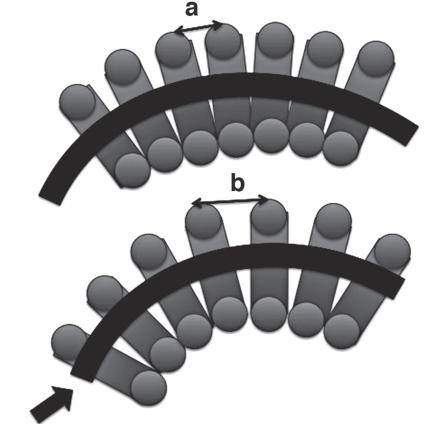
The length of the SR wire should be set according to the length of the secondary coil and to the sum of the distance of the pitch of the primary coil. However, the final coil is often inserted into the coil complex which has a dispro- portionally smaller space than the coil's primary setting. This disproportion creates a severe bend of the secondary coil loop and results in spreading between the primary coil pitches. If the coil is involved in short-cycle replacement with the pushing direction towards the outer track of the primary winding of the coil (Figure 1), the position of the SR line that corresponds to pitch of the first loops gradually deviates from the primary pair of the pitch. Thus, the early consumption of the SR line may result in a shortage of SR line at the end of the second loops, and create a contraction of the first coil loops. When several first coil loops at the most caudal part of the coil are compressed, the behavior of the loops resembles the behavior drawing a piece of cloth through the hand. Finally, the coil tail looses flexibility due to no lack of space of the pitch interval among the first loops of the coil, and the coil tail becomes a stiff wire.
Figure 1.
The influence of the enlargement of gaps in pitches. A) Normal pitch at the prescribed loop diameter. B) Enlarged gap between pitches on inserting the coil into the narrow space. Note the relative shortage of SR line (arrow). SR: stretch resistance.
Experiments in a silicone model using commercial coils
A 3 mm diameter silicon saccular aneurysm model was created. In order to recreate the final phase of embolization, squeezing the smaller coil into the space between the coil complexes, the inadequately larger coil (4 mm diameter, 80 mm long) was chosen to fill the aneurysm. Three types of coils with SR functions from different makers (GDC-10 Ultrasoft (Boston Scientific, Flemont, USA), Ultipaq Helical 10 Cerecyte SR (Micrus, San Jose, USA), ED Coil Extrasoft (Kaneka, Kanagawa, Japan)), and a non-SR coil (ED Coil Extrasoft (non-SR) (Kaneka)) were used. Experiments were repeated three times per coil, for a total of 12 repetitions. For each repetition, the coil was inserted through the preshaped microcatheter (Excercior SL 10, preshaped 90 degrees (Boston Scientific, Flemont, USA) and placed in the center of the aneurysm (Figure 3).
In vitro experiments with the magnified coil model
In order to visualize the internal coil, magnified coil model was created 12 times. The diameter of the first loops and total coil length were 3 mm and 570 mm, respectively. Coil pitches were set to 114% of the diameter of the first loops. The primary coil line (first loops) was made from fishing line and the SR line wire was made of cotton thread (Figure 4). The coil was straight without the helical or complex shape of second loops in order to simplify the analysis. The length of SR line was set to correspond with the total coil length in the straightened state. The SR line was fixed at the point of the head and tail of the coil model. In order to simulate the unusually strong bending state, the coil model was inserted and folded two-dimen- sionally into a bellows shape and inserted by force into the thin rectangular translucent box made from acrylic plate. The experiment was performed using two boxes: one 55 mm and another 35 mm wide.
Numerical verification
We calculated how many millimeters the length of the SR line should be required as the total of spreading distances between the primary coil loops, when the SR coil was forcibly rolled smaller than its defined size (smaller than the diameter of the secondary coil. The specification of the coil and SR line was set as follows: 1) inner pitches of the 1st loops and the inner alignment of the second loop always were in contact with each other; 2) the helical coil type of the three-dimensional structure was ignored; 3) the SR line always coursed through the center of the first loops; 4) the coils were always rolled equally, 5) the length of the SR line was set to be equal to the total coil length of the assumed centerline of the first loops. The Kaneka extrasoft coil was used for coil model data for this analysis. When each coil was rolled into a diameter smaller than the prescribed size, the extension length of the coil due to spreading of first loops pitches was calculated (Table 1). The initial coil length was defined as the total distance of the virtual line passing through the center point of the first loops in the rolled state with proper shape memory of the second loop. The SR line was usually set in the same length with this initial coil length.
Table 1 .
| Coil type | total number |
gap
between pitchesl |
predicted
length |
calculated
length of required SR line on insert- ing vari- ous space |
||||||||
|---|---|---|---|---|---|---|---|---|---|---|---|---|
| Extrasoft (ES) | of | (mm) |
of SR
lne2 |
required
length of SR line |
shortage of
SR line |
|||||||
| (Kaneka) |
1
st
coil
loop |
per pirch | per coil |
(center
course 3) |
1.0 | 2.0 | 3.0 | 4.0 | 1.0 | 2.0 | 3.0 | 4.0 |
| 1.5 × 10⁻¹⁰ES | 236.571 | 0.0073 | 1.720 | 10.0 | 11.6 | 1.6 | ||||||
| 1.5 × 20-10ES | 473.143 | 0.0073 | 3.440 | 20.0 | 23.2 | 3.2 | ||||||
| 1.5 × 30-10ES | 709.714 | 0.0073 | 5.160 | 30.0 | 34.8 | 4.8 | ||||||
| 2.0 × 20-10ES | 501.224 | 0.0049 | 2.457 | 20.0 | 24.6 | 20.0 | 4.6 | 0.0 | ||||
| 2.0 × 30-10ES | 751.837 | 0.0049 | 3.686 | 30.0 | 36.9 | 30.0 | 6.9 | 0.0 | ||||
| 2.0 × 40-10ES | 1002.449 | 0.0049 | 4.914 | 40.0 | 49.2 | 40.0 | 9.2 | 0.0 | ||||
| 2.0 × 60-10ES | 1503.673 | 0.0049 | 7.371 | 60.0 | 73.8 | 60.0 | 13.8 | 0.0 | ||||
| 2.0 × 80-10ES | 2004.898 | 0.0049 | 9.829 | 80.0 | 98.4 | 80.0 | 18.4 | 0.0 | ||||
| 3.0 × 30-10ES | 790.130 | 0.0030 | 2.345 | 30.0 | 38.8 | 31.5 | 30.0 | 8.8 | 1.5 | 0.0 | ||
| 3.0 × 40-10ES | 1053.506 | 0.0030 | 3.127 | 40.0 | 51.7 | 42.0 | 40.0 | 11.7 | 2.0 | 0.0 | ||
| 3.0 × 60-10ES | 1580.260 | 0.0030 | 4.691 | 60.0 | 77.5 | 63.1 | 60.0 | 17.5 | 3.1 | 0.0 | ||
| 4.0 × 40-10ES | 1077.333 | 0.0021 | 2.293 | 40.0 | 52.9 | 43.0 | 40.9 | 40.0 | 12.9 | 3.0 | 0.9 | 0.0 |
| 4.0 × 60-10ES | 1616.000 | 0.0021 | 3.440 | 60.0 | 79.3 | 64.5 | 61.4 | 60.0 | 19.3 | 4.5 | 1.4 | 0.0 |
| 4.0 × 80-10ES | 2154.667 | 0.0021 | 4.587 | 80.0 | 105.7 | 86.0 | 81.8 | 80.0 | 25.7 | 6.0 | 1.8 | 0.0 |
Results
Experiments in a silicone model using commercial coils
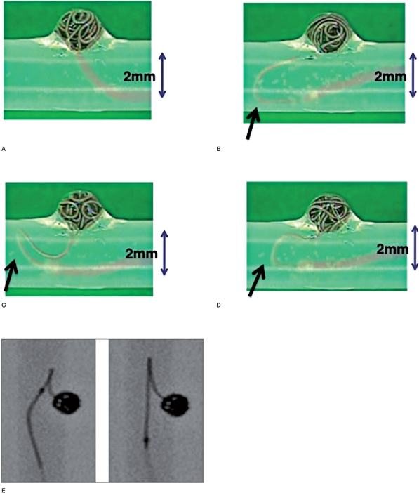
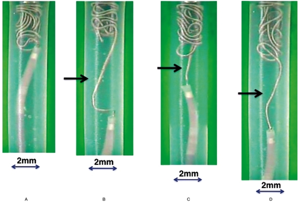
The catheter kickback phenomenon with straightening of the coil tail was observed with all repetitions (n=9) using SR type coils, and was not observed any repetitions (n=3) using non-SR coils (Figure 2). The point of coil prolapse (kickback start time) was slightly different between coil types. A similar phenomenon was observed during simulation of endovascular trapping when the same coils were inserted into the narrow 2mm diameter cylinder (Figure 3.
Figure 2.
Kickback phenomenon in saccular aneurysm model showing various types of coils inserted into an inadequately small diameter model. Here 4mm diameter x 8 mm long coils are inserted into the 3 mm diameter aneurysm model. A) ED extrasoft coil non SR type. B) ED extrasoft SR type. C) GDC ultrasoft. D) Cerecyte ultipaque. E) Fluoloscopic image inserting ED extrasoft SR type. Abbreviations: ED: electrically detachable, GDC: Guglielmi detachable coil.
Figure 3.
Various brands of 4 mm diameter × 8 mm long coils and the cylinder model of the kickback phenomenon. Cylinders have inadequately small diameters. Here 4 × 8 mm coils are inserted into 2 mm diameter cylinders. A) ED extrasoft coil non SR type. B) ED extrasoft SR type. C) GDC ultrasoft. D) Cerecyte ultipaque.
In vitro experiments with the magnified coil model
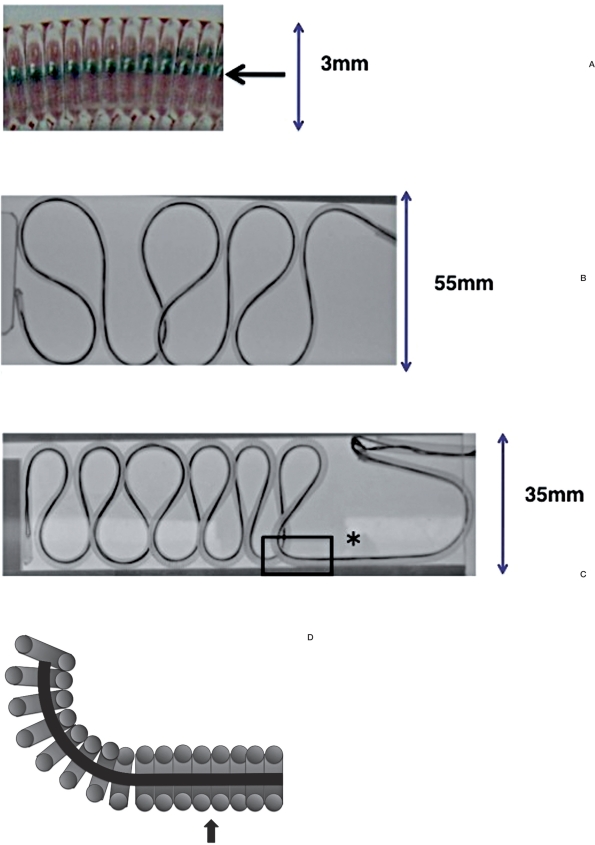
Although the coil model was found to bend smoothly in the wide rectangular space (55 mm). it straightened upon insertion into the narrow rectangular space (35 mm) (Figure 4).
Figure 4.
SR coil model made of fishing line. A) Magnification of 16X. The SR line (arrow) fixed at the coil tip and the lengths of the tail and the coil were the same. B) The coil model is found to bend smoothly in the wide rectangular space (55 mm width) (2X). C) The coil model is found to straighten in the narrow one (asterisk) (35 mm width). The straightening part is boxed. D) Schema of the boxed part of straightening (arrow) in (C).
Numerical verification
Extension of coil length due to the spreading pitches of the first loops inevitably resulted in a shortage of SR line. There was a greater degree of discrepancy between the coil length the smaller the coil rolls (Table 1). For example, if a coil 4mm in diameter and 80mm long was regularly inserted into a 2 mm tubular space, the coil length extended to 86 mm. Therefore the SR line was 6mm too short assuming that it coursed centrally and did not shift. Similarly, if a coil 2 mm in diameter and 40 mm long was rolled into a 1mm tube, the SR line would be 9.2 mm too short. The shortage of the SR line was found to reach a maximum of 32% of prescribed length of SR line, which was observed as 25.7 mm lack when the 4 x 80mm coil was inserted into the 1mm space.
However, as observed in magnified coil model, if the bending direction frequently changes or the coil is tightly rolled, the course of SR line will shift to the periphery of the first loops. This condition is another factor in the creation of a shortage of SR line.
Discussion
The role of finishing coil is important in the final phase of coil embolization. Typically, among the coils previously placed, a very soft coil is used more often for gap filling. While finishing coil insertion, strong resistance or catheter kickback can be regarded as a sign of a lack of remaining space in the coil mass. At that point, the operation must be completed or the last coil must be withdrawn. In case of 1 to 2 mm of kickback of the coil tail, the coil may be successfully placed by repositioning the microcatheter. However, the forcible push of the microcatheter to prevent the kickback will adds to the risk of penetration of the wall of the aneurism. In some cases, the catheter repeats the kickback at the same points. And even if the coil tail which could be successfully squeezed in the aneurysm due to balloon-assisting it may herniate into the parent vessel after detachment. Because a herniated coil creates a greater risk of thrombosis 9, it is occasionally necessary to put the coil into the aneu- rismal sac once more using stent6,7.
This microcatheter kickback phenomenon has been understood to be due to a counteraction against the catheter by the prolapsed coil tail. This counteraction happens either because there is no more space to insert the last coil, or because of a loss of freedom at the catheter tip because of stiffness of the terminal joint of the delivery wire 8. Improvements to the detaching system on the newest coils, however, have not resolved this problem. Empirically, stretch-resistance (SR) coils seem to promote this phenomenon. The length of the SR line in each coil is adequately set considering the curve of second loop, a central position, and a regular course inside the first loops. Due to the spread distances between the pitches of 1st loops and the shift of the SR line to the periphery may cause a discrepancy between the prescribed length and the actual length necessary to keep the morphological regularity of coil pitches and curve. As a result, early consumption of the SR line must be taken from the end of coil, and this situation is represented as the straightening and loss of flexibility (due to coil pitch sticking and linearization similar to a tightly closed accordion). According to the present experimental study, this phenomenon is realized when the coil is inadequately rolled in a small space. This is similar to the final stage of embolization where the finishing coil should be squeezed into the narrow remnant space in the coil mass. This straightening phenomenon can occur not only in saccular packing but also in endovascular trapping, sinus packing of a dural arteriovenous fistula, or in feeder occlusion for tumor embolization, if a large and/or long coil is used for a relatively small caliber space.
The present study verified that this specific phenomenon is common in all coils with SR function, but the degree of expression is slightly different between different types of coils from various makers. The differences may be caused by the differences in first loops filament diameter, intervals between pitches, systems of detachment, and the stiffness and shape of the detaching zones of each coil.
Precautions to avoid this kickback behavior are considered. As for the technical strategy, use of non-SR coils may be available. However, it is quite impractical because of the high risk of unraveling. The finishing coil must be safely retrieved or repositioned in case that it is squeezed into the remnant space. Non-SR coils have no benefits in the final stages of embolization. The best way may be to use multiple small and short coils, not to use one long coil. Also, if the target diameter is obvious, an inappropriately large coil should not be used. As for the resources of coil itself, the SR line should be set a little longer than needed in order to provide room to deal with the relative shortage due to the tight rolling. However, abnormal bending and deflection of coils may result in high friction in the microcatheter. If the coil is withdrawn, stretching will easily occur due to its flexibility. Therefore, it is necessary to give an ideal margin that neither interferes with insertion of the coil nor causes straightening. Another solution would be invention of a very small diameter coil that fits into the narrowest space. For example, the smallest coil with a 1.5 mm diameter (extrasoft, Kaneka) is useful for the prevention of straightening 10,11.
The shortage of SR line when a 1.5 mm diameter coil is inserted into a 1mm space is less than that in the same situation using the 2.0 mm coil (1.6~4.8 mm and 4.6~9.2 mm shortages, respectively) (Table 1). In order to prevent straightening, which can be a cause of kickback, soft and small SR coils should be used as finishing coils.
The finishing SR coils should be designed based with the consideration of balance between the benefits and disadvantages.
Conclusion
Kickback due to straightening is a specific complication in SR coils. Coil kickback is caused by the relative shortage of SR line, subsequent condensation of pitches of first loops at the coil end, and loss of flexibility of the coil tail. This particularly occurs when a longer coil is rolled into an inadequately smaller space. In that case, the distance between pitches of the first loops is enlarged, and the SR line travels outside the orbit with passing a long stretch. Straightening is a main factor in the kickback phenomenon. It is important to select a shorter SR coil as the final coil for insertion into a tight space in order to avoid the unpredicted and non-revisable kickback due to the straightening phenomenon. Development and reform of coil design and hardware is also needed in order to resolve this complication.
References
- 1.Moret J, Cognard C, Weill A, et al. The reconstruction technique in the treatment of wide-neck intracranial aneurysms: long-term angiographic and clinical results. J Neuroradiol. 1997;24:30–44. [PubMed] [Google Scholar]
- 2.Lubicz B, Leclerc X, Gauvrit JY, et al. Hyperform remodeling balloon for endovascular treatment of wideneck intracranial aneurysms. Am J of Neuroradiol. 2004;25:1381–1383. [PMC free article] [PubMed] [Google Scholar]
- 3.Selhar R, White P, Horribine L, et al. initial experience with a new soft stretch-resistant coil. J Neuroradiol. 2004;31:409–412. doi: 10.1016/s0150-9861(04)97026-5. [DOI] [PubMed] [Google Scholar]
- 4.Dinc H, Kuzeyli K, Kosucu P, et al. Retrieval of prolapsed coils during endovascular treatment of cerebral aneurysms. Neuroradiology. 2006;48(4):269–272. doi: 10.1007/s00234-006-0051-x. (Epub 2006) [DOI] [PubMed] [Google Scholar]
- 5.Sugiu K, Martin JB, Jean B, et al. Rescue balloon procedure for an emergency situation during coil embolization for cerebral aneurysms. Technical note. J Neurosurg. 2002;96:373–376. doi: 10.3171/jns.2002.96.2.0373. [DOI] [PubMed] [Google Scholar]
- 6.Luo CB, Chang FC, Teng MM, et al. Stent management of coil herniation in embolization of internal carotid aneurysms. Am J Neuroradiol. 2008;29:1951–1955. doi: 10.3174/ajnr.A1268. [DOI] [PMC free article] [PubMed] [Google Scholar]
- 7.Lavine SD, Larsen DW, Giannotta SL, et al. Parent vessel Guglielmi detachable coil herniation during widenecked aneurysm embolization: treatment with intracranial stent placement: two technical case reports. Neurosurgery. 2000;46:1013–1017. [PubMed] [Google Scholar]
- 8.Lubicz B, Leclerc X, Gauvrit JY, et al. Three-Dimensional Packing with Complex Orbit Coils for the Endovascular Treatment of Intracranial Aneurysms. Am J Neuroradiol. 2005;26:1342–8. [PMC free article] [PubMed] [Google Scholar]
- 9.Workman MJ, Cloft HJ, Tong FC. Thrombus formation at the neck of cerebral aneurysms during treatment with Guglielmi detachable coils. Am J Neuroradiol. 2002;23:1568–1576. [PMC free article] [PubMed] [Google Scholar]
- 10.Sadato A, Taki W, Ikeda Y, et al. Immediately detachable coil for aneurysm treatment. Am J Neuroradiol. 1995;16:1459–1462. [Google Scholar]
- 11.Sadato A, Hayakawa M, Irie K, et al. Initial experiences with a new detachable coil (type 10 ED coil) for treating intracranial aneurysms. Jpn J Neurosurg (Tokyo) 2007;16:954–958. (In Japanese) [Google Scholar]


