

Abstract
During in vivo intracerebral infusions, the ability to perform accurate targeting towards a 3D-specific point allows control of the anatomical variable and identification of the effects of variations in other factors. Intraoperative MRI navigation systems are currently being used in the clinic, yet their use in nonhuman primates and MRI monitoring of intracerebral infusions has not been reported. In this study rhesus monkeys were placed in a MRI-compatible stereotaxic frame. T1 MRIs in the three planes were obtained in a 3.0T GE scanner to identify the target and plan the trajectory to ventral postcommisural putamen. A craniotomy was performed under sterile surgical conditions at the trajectory entry point. A modified MRI-compatible trajectory guide base (Medtronic Inc.) was secured above the cranial opening and the alignment stem applied. Scans were taken to define the position of the alignment stem. When the projection of the catheter in the three planes matched the desired trajectory to the target, the base was locked in position. A catheter replaced the alignment stem and was slowly introduced to the final target structure. Additional scans were performed to confirm trajectory and during the infusion of a solution of gadoteridol (ProHance, Bracco Diagnostics; 2 mM/L) and bromophenol blue (0.16 mg/ml) in saline. Monitoring of the pressure in the infusion lines was performed using pressure monitoring and infusion pump controller system (Engineering Resources Group Inc.) in combination with a MRI-compatible infusion pump (Harvard). MRI during infusion confirmed successful targeting and matched postmortem visualization of bromophenol blue. Assessment of the accuracy of the targeting revealed an overall 3D mean ± SD distance error of 1.2 ± 0.6 mm and angular distance error of 0.9 ± 0.5 mm. Our results in nonhuman primates confirm the accuracy of intraoperative MRI intracerebral navigation combined with an adaptable, pivot point-based targeting system and validates its use for preclinical intracerebral procedures.
Keywords: Magnetic resonance imaging (MRI), Stereotaxic surgery, Intracerebral infusions, Convection-enhanced delivery, Intracerebral targeting, Putamen
INTRODUCTION
Due to their behavioral and anatomical complexity, nonhuman primates are ideal subjects for preclinical evaluation of invasive technologies requiring intracerebral targeting (3,11,12). While stereotaxic atlases [e.g., (15)] provide basic neuroanatomical information, the individual variability between rhesus monkey subjects necessitates the complementary use of magnetic resonance imaging (MRI)-guided surgical techniques to increase aiming success (20). Yet, as classical stereotaxia is non-MRI compatible, this implies that the method can only benefit of MRI data during the target planning stage. The need for accuracy is further enhanced when studying in vivo dynamics of infusates in the brain parenchyma [e.g., (18), Infusion Physics Study Group, 2009, http://www.pdonlineresearch.org/responses/803/83/whatced; last seen 1/3/2011]. During in vivo infusions, the ability to perform accurate targeting towards a 3D-specific point inside a given structure allows control of the anatomical variable and identification of the effects of variations in other factors (Infusion Physics Study Group, 2009, http://www.pdonlineresearch.org/responses/803/83/factors-affecting-drug-distribution-through-infusion). In this context, accuracy (degree of closeness of a measured or calculated quantity to its actual value) (21) can be defined as the distance between the planned target and the actual positioning. Accuracy is closely related to precision, also called reproducibility or repeatability, the degree to which further measurements or calculations show the same or similar results.
In nonhuman primates MRI-compatible intracerebral catheter insertion platforms, such as arrays, have been developed for in vivo monitoring of infusions [e.g., (2,9)], but they lack flexibility for intraoperative modification of the angle of catheter insertion based on MRI feedback. Intraoperative MRI navigation systems are currently being used in the clinic for tumor biopsies and placement of electrodes for deep brain stimulation (DBS) [e.g., (14,17,22)]. These systems are not traditionally used for cell transplantation and gene transfer and their application during preclinical testing will facilitate its clinical translation.
Here for the first time we describe in nonhuman primates the use and accuracy of an intracerebral targeting method that employs a frameless, pivot point-based guide system that allows different trajectory angles and applies intraoperative MRI guidance.
MATERIALS AND METHODS
Subjects
Three adult male rhesus monkeys (Macaca mulatta; 5–7 years old, 6–7 kg) were used in this study. One animal (R95106) received a unilateral infusion and two animals (R03044, R03064) received bilateral ones. Animals were housed individually on a 12-h light/dark cycle and received food and water ad libitum. The experiments were performed according to the federal guidelines of animal use and care and with approval of the local IACUC.
Surgical Placement of the Trajectory Guide Base
Intraoperative MRI guidance of the catheter was performed using a pivot point-based MRI-compatible external trajectory guide (Medtronic Inc.). Modifications were made to this system to adapt it for the placement of catheters by the addition of a guiding insert, customized base to fit the nonhuman primate skull and the addition of an alignment pin (Fig. 1). Placement of the system base was performed under sterile conditions using MRI-guided stereotaxic surgery. Before the procedure the animal was food deprived overnight, anesthetized in its home cage with ketamine (10–15 mg/kg, IV), and prepared for surgery under isoflurane (1–5%) with the aid of a breathing mask. The animal was intubated and during the surgical procedure received isoflurane (1–3%) and its vital signs monitored. The animal was placed in the stereotaxic frame using the coordinates obtained during the baseline MRI. An 8–10-cm midsagittal skin incision was made over the superior portion of the head. The aponeuroses on both sides of the sagittal ridge were incised using electrocautery. The entry point was located on the surface of the skull using the alignment pin (inserted in the base attached to a stereotaxic micro-manipulator and following the coordinates defined by a baseline MRI). The footprint of the system base was marked on the skull using a skin marker. A 6-mm-diameter craniotomy was drilled at the planned entry area corresponding to the opening of the trajectory guide base and the dura was retracted to expose the brain. Using the alignment pin for placement, the base was mounted to the skull over the craniotomy with three small self-tapping screws.
Figure 1.

Pictures depicting the intracerebral infusion system. (A) MRI-compatible trajectory guide. (B) Micromanipulator with alignment pin inserted in the alignment stem of the base. (C) Base with remote introducer and guiding insert in place. (D) Full system set up for intracerebral infusions.
Magnetic Resonance Imaging (MRI)
All imaging was performed in a 3-Tesla GE SIGNA (GE Healthcare; Waukesha, WI) MRI scanner. A custom 3-inch diameter, receive-only surface coil (MR Instruments, Inc., Minneapolis, MN) was used for scanning. For the imaging procedures, the animal was food deprived overnight. After sedation with ketamine (10–15 mg/kg, IM) the animal was intubated and an iv catheter was placed for fluid administration. Anesthesia was continued under isoflurane (1–3%) for the duration of the scan. Atropine (0.02–0.05 mg/kg, IM) was also administered. Vital signs (heart rate and blood oxygen, respiration, and temperature) were monitored during the procedure using MRI-compatible instruments. The animals were wrapped for warmth and placed in a MRI-compatible stereotaxic frame. The placement of the monkey’s head in the frame was recorded.
Baseline Scans
Presurgical MRI scans consisted of 3D T1-weighted (T1W) images with an inversion-recovery (IR) prepped, fast gradient-echo (IR-fGRE) sequence. The scanning parameters were an inversion time (TI) = 450 ms, repetition time (TR) = 9.2 ms, echo time (TE) = 4.1 ms, receiver bandwidth = ±25 kHz. The matrix size was 256 × 224 × 128 (X × Y × Z) and the scan time was 7:50 min. The 3D T1W scans produced 124 coronal 0.8-mm-thick contiguous slices. In addition to the T1W scan, dual-echo proton-density- and T2-weighted fast spin echo, diffusion tensor imaging, and MR angiography were also obtained, although they were not used specifically for the targeting.
Before surgery the 3D T1W MRIs were used to visualize the target structure in three planes (sagittal, axial, and coronal) and identify the entry point of the catheter, which defines the placement of the trajectory guide base. The anteroposterior (AP) zero plane was identified by visualization of the ear bars (filled with contrast agent) of the stereotactic frame. The dorsoventral (DV) zero was defined as the surface of the brain at the area of insertion and the mediolateral (ML) zero was defined as the middle of the sagittal sinus. Based on the three sets of images a target point was determined and a trajectory was planned to define the location of the entry at the skull, where the base is placed. The distance was calculated based on the zero coordinates previously defined, using GE MRI software.
Targeting Scans
After the base was placed on top of the opening of the skull (entry point) and the meninges opened, an identical 3D T1W scan with the IR-fGRE protocol was run. These scans were used to select the final target, trajectory angle, and depth to the target within the monkey putamen (Fig. 2). The procedure was performed in the MRI console and annotated electronically on the MR image. Afterwards, dynamic targeting imaging was performed using a 3D T1W spoiled gradient echo (3D SPGR) sequence with TR = 21 ms, TE = 2.4 ms, flip angle = 34°, bandwidth = ±16.7 kHz, in-plane FOV = 140 × 105 mm (0.75 phase FOV), matrix = 256 × 224 × 64, and 64 contiguous coronal slices each 0.8 mm thick. The scanning time was 4:03 min.
Figure 2.

Intraoperative baseline T1 MRI imaging of the brain of a rhesus monkey for planning catheter trajectory, co-corresponding to (A) sagittal, (B) axial, and (C) coronal plane based on selected target point (black dot in the postcommissural ventral putamen nucleus). Scale bar: 10.3 mm (A), 10.2 mm (B), 10.0 mm (C).
Infusion T1 Mapping
For the infusion monitoring, a pair of 3D SPGR scans with two flip angles (6° and 34°) were used to map T1. The sequence parameters were the same as the dynamic targeting scan except the slice thickness was increased to 1.6 mm. The acquisitions of the two flip angles were alternated.
Targeting Procedure
For the final targeting planning and intracerebral introduction of the catheter the monkey was transported back to the MRI suite. The animal was placed in the stereotaxic frame following similar coordinates used for baseline MRI and surgery. A cannula filled with sterile degassed water was inserted into the stem of the trajectory guide. Several targeting scan (3D T1W) MRIs were sequentially taken to aid in the positioning of the cannula guide in the planned AP and ML planes (Fig. 3). When the trajectory angle (antero-postrerior, medio-lateral direction) of the fluid filled cannula was confirmed to be on target, the alignment stem was locked into position. The fluid-filled cannula was removed and the remote introducer was fastened to the stem. The guiding insert was placed in the guiding stem. The catheter for the infusion was threaded through the remote introducer and the guiding insert and fastened to the remote introducer by a locking mechanism. The catheter was a fused silica single endport cannula with a step and a silica stylet. Its dimensions were: tip—outer diameter (OD) = 0.35 mm, inner diameter (ID) = 0.25 mm, length = 3.0 mm; shaft—OD = 0.65 mm, ID = 0.32 mm, length = 100.0 mm.
Figure 3.
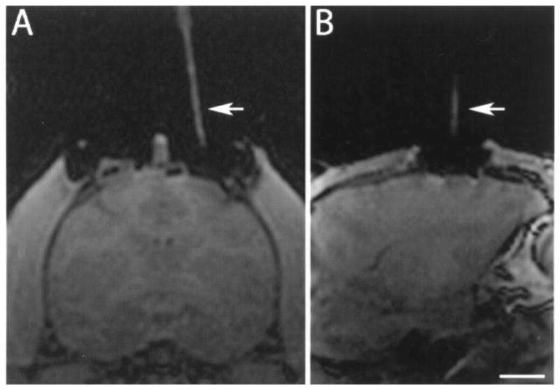
T1 MRI imaging of the brain of a rhesus monkey showing alignment stem (arrow) filled with degassed water inserted in the stem before catheter introduction in the (A) coronal and (B) sagittal planes. The target point is not visible in these scans due to the angled trajectory. Scale bar: 10.0 mm (A), 11.2 mm (B).
Silica infusion lines were used to connect the catheter to 5-cc syringes that were placed in a MRI-compatible syringe pump attached to the control mechanism of the standard Harvard apparatus PHD 2000. Monitoring of the pressure in the infusion lines was performed using pressure monitoring and infusion pump controller system from the Engineering Resources Group, Inc. The infusion lines were primed with degassed deionized water and then filled with the infusate solution. The catheter stylet was extended 1–2 mm from the lowest step of the catheter in preparation for catheter insertion. The MRI-compatible infusion pump was placed at approximately the same height as the target. Care was taken to minimize manipulation of the system. After pressure of the lines was stabilized, the catheter was introduced into the brain, advancing the remote introducer at approximately 5–7 mm/min. At half of the measured depth, another targeting 3D T1W MRI was performed to calculate the remaining depth from catheter tip to target (Fig. 4A–C). With this new information the catheter was further introduced and a new targeting 3D T1W MRI was performed to confirm the catheter has reached its target (Fig. 4D–F). After the pressure was stabilized the stylet was retracted 8 mm. When the pressure stabilized again the relative pressures were zeroed and the infusion started.
Figure 4.

T1 MRI imaging of the brain of a rhesus monkey during insertion of infusion catheter to confirm trajectory and plan final depth of introduction (A, B, C) and final catheter placement (D, E, F). Arrow points to inserted catheter. Images of (A) sagittal, (B) axial, and (C) coronal plane are based on selected target point. Scale bar: 8.2 mm (A, D), 7.3 mm (B), 10.0 mm (C, F), 6.8 mm (E).
Infusion
Intracerebral infusion was performed under MRI monitoring. A solution of gadoteridol (ProHance, Bracco Diagnostics; 2 mM/L) and bromophenol blue (0.16 mg/ml) in saline was used for in vivo MRI and postmortem visualization of the infusate. A total volume of 100 μl was infused at a steady rate of 1 μl/min or a 10% duty pulse cycle of 10 μl/min. Infusion was monitored with T1 mapping from two 3D SPGR scans at two flip angles (6° and 34°) as described above. Mapping volumes were obtained every 4.5 min. Imaging time was recorded.
Assessment of the Accuracy of the Targeting
The accuracy of the targeting was calculated as the distance between the intraoperative planned target location in the postcommissural putamen and the actual final placement of the catheter tip. Target locations were annotated on the preplacement T1-weighted MRI scans. The annotated preplacement scan was registered to a T1-weighted MRI taken just after catheter insertion. The catheter tip location was read from the postplacement scan, and compared to the annotated target location on the co-registered preplacement scan.
Necropsy, Preparation of Tissue
After infusions were completed and postinfusion scans obtained, the animals were transported to the necropsy room. The monkeys were euthanized by pentobarbital administration (25 mg/kg, IV). The brain was rapidly removed from the calvaria and immersed in ice-cold saline for 10 min. The brain was then cut (2 mm thickness) in the coronal plane using a calibrated Lucite brain slice apparatus. Tissue slabs were placed on glass slides and photographed in both sides.
RESULTS
Catheter Positioning
In all cases the catheter tips were aimed at the center of the ventral portion of the postcommissural putamen. Every insertion successfully targeted this area; it was confirmed in vivo by the location of contrast agent in MRI (Fig. 5A–C) and postmortem by distribution of bromophenol blue (Fig. 5D).
Figure 5.

T1 MRI imaging of the brain of a rhesus monkey after completing the infusion in the (A) axial, (B) coronal, and (C) sagittal planes. (D) Gross anatomy image of a coronal view of a rhesus monkey brain showing the distribution of bromophenol blue in the target structure. Arrow indicates catheter end. Scale bar: 20.7 mm (A), 14.3 mm (B), 18.5 mm (C), 10.0 mm (D).
The catheter was inserted following a combined fronto-dorsal, medio-lateral angled trajectory to maximize the distance of the catheter tip from the nearest putamenal boundary, while maximizing the length of the distal catheter within the putamen. The actual trajectory of every case closely matched the planned trajectory, as observed in Figure 6.
Figure 6.

Overlapped T1 MRIs of the planned trajectory and actual catheter placement, for each of the reported cases. A red cross identifies the planned catheter tip location in the overlaid targeting MRIs. (A) Rh91070, right hemisphere; (B) Rh03044, left hemisphere; (C) Rh03044, right hemisphere; (D) Rh03064, left hemisphere; (E) Rh03064, right hemisphere. Scale bar: 10.0 mm.
Trajectory angles were measured with respect to a vertical line in the coronal plane. Table 1 shows the catheter trajectory angles and insertion depth measured just after insertion. ML angle, measuring rotation in coronal plane, was around 10° angling from medial to lateral in all cases. AP angle measured anterior to posterior angular offset within the sagittal plane. The catheter depth (measured from the brain surface to the catheter tip) was approximately 21 mm in all cases.
Table 1.
Catheter Trajectories and Intraputamenal Positions
| Catheter Trajectory
|
Tip Position in Putamen
|
|||||
|---|---|---|---|---|---|---|
| Subject | Side | ML angle | AP Angle | Depth (mm) | Tip Dist. (mm) | Depth (mm) |
| R91070 | right | 9.5° | 3.5° | 21.0 | 2.4 | 5.3 |
| R03044 | right | 10.1° | 3.4° | 20.3 | 1.7 | 6.0 |
| R03044 | left | −9.3° | 3.3° | 20.8 | 1.4 | 6.3 |
| R03064 | right | 11.1° | 4.0° | 21.5 | 1.5 | 7.0 |
| R03064 | left | −7.0° | 6.4° | 20.4 | 1.5 | 5.0 |
| Mean | 9.4° | 4.1° | 20.8 | 1.7 | 5.9 | |
| SD | 1.5° | 1.3° | 0.5 | 0.4 | 0.8 | |
See Catheter Positioning section for details. Tip distance corresponds to the distance from the tip of the catheter to the nearest putamen boundary. Depth corresponds to the length of the catheter within the putamen, from the tip to the nearest putamen boundary. Trajectories between cases differed due to variations in the skull, brain size, as well as the placement of the base in the skull.
The last two columns of Table 1 describe the location of the catheter tip within the putamen. The putamen width (in the ML direction) was 4–6 mm in plane of insertion, meaning that an ideal trajectory could locate the tip at most 2–3 mm from the nearest boundary. The tip was located well under 1 mm from the ML center in all cases, and a minimum of 1.4 mm from the nearest boundary. The length of catheter within the putamen was between 5 and 7 mm.
Targeting Accuracy
Table 2 shows the distance between the planned target location and the final placement of the catheter tip for each of the five 100-μl infusions (91070, 03044 left/right, 03064 left/right). The coordinates of the target in the ML, DV, and AP directions were compared to those of the final catheter position. The differences along each of these three axes are shown in the columns labeled ML, DV, and AP. The three-dimensional Euclidean distance between the two points (“Distance”) was 1.1 ± 0.6 mm (mean ± SD). It is important to distinguish systematic error, which can often be corrected by calibration, from random error, which identifies fundamental limits in the accuracy of the system and the method of measurement. The means of the ML, DV, and AP differences are indicators of the systematic error, while their SDs are measures of the random error.
Table 2.
Difference Between Catheter Tip Target Location and Actual Tip Location After Placement
| Target–Placement Difference (mm)
|
||||||
|---|---|---|---|---|---|---|
| Subject | Side | ML | DV | AP | Distance | Angular (ML, AP) Distance |
| R91070 | right | −0.7 | 0.0 | −1.0 | 1.2 | 1.2 |
| R03044 | right | −0.2 | −0.1 | 0.0 | 0.2 | 0.2 |
| R03044 | left | −0.4 | 0.9 | −1.6 | 1.9 | 1.6 |
| R03064 | right | 0.2 | 1.0 | −0.8 | 1.3 | 0.8 |
| R03064 | left | 0.7 | −0.5 | 0.0 | 0.9 | 0.7 |
| Mean | −0.1 | 0.3 | −0.7 | 1.1 | 0.9 | |
| SD | 0.5 | 0.7 | 0.7 | 0.6 | 0.5 | |
ML, DV, and AP measure the differences along the mediolateral, dorsoventral, and anteroposterior axes. The “Distance” column shows the corresponding Euclidean distance between the target and placement. Angular Distance refers to the Euclidean distance in the ML and AP directions only—the two directions most affected by the angles of the catheter trajectory.
The distance error in the ML and AP locations was determined primarily by the trajectory angle of the cannula guide, while the DV location was determined by the depth of insertion. Thus, the two-dimensional Euclidian distance in the ML–AP plane (or angular distance) yielded a single measure of trajectory accuracy. The mean angular distance for this study was 0.9 ± 0.5 mm (Table 2, last column). The (ML, AP) differences for each infusion were plotted in Figure 7. In this plot, the target point is the origin, at the center of the graph, and the points represent the actual trajectories. Note that in the ML direction, the errors were small and were distributed between the left and right of the target. This is the narrow dimension of the putamen, with the least tolerance for error, and in this study the catheters were placed very near the ML center. In the AP direction, errors tended toward the posterior (mean of −0.7), and three of the placements have differences greater than any of those in the ML direction. However, along this axis, the putamen is elongated and these errors did not tend to put the catheter tip any closer to the putamen boundary. Thus, less accuracy is required in this direction to obtain a satisfactory placement within the putamen.
Figure 7.

Graph representing mediolateral (ML) and anteroposterior (AP) positioning differences (Euclidean angular distance) for each infusion. The center represents the target position.
DV positioning (determined by the depth of insertion) tended toward placements slightly deeper than planned (mean of 0.3). Clear visualization of fine catheter end tip can be difficult and we purposefully chose to err towards a deeper location. Generally, a deeper intra-putamenal placement is advantageous for limiting the chances of backflow carrying infusate out the ventral putamen border, as long as the tip remains in the putamen, a few millimeters from the boundaries.
DISCUSSION
Our results in nonhuman primates confirm the accuracy of intraoperative MRI intracerebral navigation combined with a flexible, pivot point-based targeting system and validates its use for preclinical intracerebral procedures.
In animals, especially rodents, stereotaxic brain surgery mostly relies on using stereotaxic atlases to provide information for targeting. While this presents limitations, its use in rodents is justifiable as the animals are highly inbred, which allows replication between subjects when controlling for variables such as species, age, sex, and weight. Accurate targeting for outbred nonhuman primates is more complex. While stereotaxic atlases provide basic information for targeting, the variability between animals as well as their cost justifies the use of MRI guidance for surgical planning. Subramanian and colleagues (20) reported that stereotaxic targeting of cell transplants based on atlas guidance in rhesus monkeys has a 38.5% success compared to 80% success when MRI was used for planning the targeting. It should be mentioned that the authors defined success by postmortem observation of the needle tract inside the putamen nucleus, instead of a predefined specific area inside the nucleus.
For many years our group has successfully used MRI-guided stereotaxic brain surgery in nonhuman primates for cell transplantation (16), and in vivo (5,7, 12,13) and ex vivo gene therapy (1,6). We have observed that small differences in the placement of the monkey head in the frame during surgery compared to the baseline scan, as well as brain shifting after opening of the dura, may affect targeting accuracy. Furthermore, traditional stereotaxic systems do not permit real-time imaging monitoring of intracerebral infusions.
In the clinical setting, the controversial outcome of trials seeking to treat Parkinson’s disease by intracerebral infusion of glial derived neurotrophic factor (GDNF) (19) pointed out that delivery methods, including targeting, may affect the efficacy of the therapy. In that regard, pressure-driven (also called convection enhanced delivery) infusion studies in malignant gliomas demonstrated that accurate targeting is required to have predictable patterns of infusion (18). An example is the repositioning of cannulae to correct for targeting mistakes. Previous catheter tracts become low resistance paths that facilitate infusate motion towards those areas of less resistance. These channels have been documented to persist and affect infusate fluid motion for at least 14 days after removal of the catheter.
Frameless image-guided neurosurgery is increasingly used in the clinic, mainly for tumor biopsy or excision [e.g., (17,22)]. Although this method is attractive due to its ease of use and ample accessibility to surgical field, its applicability for guided targeting of catheters or electrodes is limited. The Medtronic StealthStation® Navigation system emerged as an alternative method, and has been mainly applied for tumor biopsy sampling and placement of DBS electrodes. It uses a “frameless” method, as it does not require a stereotaxic frame for guidance. The intracerebral navigation relies on preprocedural MRI scans that are entered into the computer system. The neurosurgeon plans the trajectories using the StealthStation®, which provides cues to guide the positioning of the trajectory guide base and stem. Although this system has several advantages (being flexibility associated to a pivot point-based and less invasiveness the most salient ones), it does not allow for intraoperative monitoring of intracerebral navigation or infusions.
In this study we combined MRI-guided stereotaxic surgery, the MRI-compatible external trajectory guide, and real-time MRI navigation. As the appropriate placement of the base is the first step to accurate trajectory, we took advantage of our current set up and experience. We used baseline MRI scans for initial planning and stereotactic techniques to define the entry point and secure the base on the monkey skull. This minimized the need of MRI-compatible surgical equipment compared to the actual infusion set up, as the placement of the skull port was performed in a surgical suite. The actual intracerebral navigation and infusion was done under 3-Tesla MRI guidance, which allowed for high resolution imaging and flexibility to adjust the trajectory as needed and correlate real-time infusion imaging data with pressure monitoring.
Our investigation revealed a 3D mean error of 1.1 ± 0.6 mm and angular distance error of 0.9 ± 0.5 mm in the targeting of the catheter. To the best of our knowledge, analysis of intracerebral targeting accuracy of navigation systems (stereotaxic or frameless) in nonhuman primates has not yet been published and, thus, we are unable to compare our data with other monkey studies. In humans, a report using equivalent navigation systems and a 1.5-Tesla interventional magnet for placement of DBS electrodes (14) described a mean error of 1.2 ± 0.7 mm. This value is in the range of our results. This is particularly encouraging considering that: 1) the tip of the catheter utilized in our report has an OD of 0.35 mm, compared to 1.2 mm of the solid ceramic mandrel that was used to guide the electrode insertion; 2) the volume of a normal rhesus monkey brain (94.6 cc) (8) compared to a normal human brain (1424.5 cc) (10) is approximately 14 times smaller, which affects image acquisition; 3) the pivot point of the external trajectory guide base to the target is further away in the human than in monkeys. Although this decreases catheter bending, less angular range increases the possibility of error. In that regard, our results suggest that the utilization of real-time imaging using a 3-Tesla MRI scanner and a custom made surface coil, plus close interaction between surgeons and MRI physicists, facilitates intracerebral visualization and accurate targeting.
There are a number of different factors limiting the accuracy with which the targeting error could be measured. For the targeting scans, the in-plane imaging resolution of the coronal 3T MRI scans was 0.547, and 0.625 mm in the ML and DV directions, respectively (although voxels dimensions were 0.547 mm2), with a slice thickness (AP resolution) of 0.8 mm. The minimum resolvable distance is at least twice the maximum voxel dimension (1.6 mm in this case). Note that nearly all of the estimated targeting errors were less than this distance, which suggests that the targeting is within the resolving power of the imaging. Additional image-related error is incurred while registering the targeting image to the postplacement image, due to limits of resolution, noise, and distortion inherent in MR imaging. Further, the manual positioning of the catheter trajectory and placement is also prone to small errors.
Beyond simple rigid registration and measurement accuracy, the brain can shift and deform significantly between the time of targeting and the completion of catheter placement (4). Trauma during the surgery and effects of the anesthesia can give rise to global deformation of the brain. The mechanical pressure of catheter insertion can further locally deform the tissue. Thus, it can become difficult to translate the initial target to the deformed coordinate system of the postplacement brain. In such cases, it may make more sense to evaluate the quality of the absolute position (i.e., distance from putamen borders, depth in the putamen) rather than the distance from the original target.
Future studies may minimize these errors further by improvements to spatial resolution (without significant degradation of the signal-to-noise ratio). This could be accomplished through improvements to RF coils, higher magnetic field strength scanners, or longer scanning protocols (e.g., more averaging). MRI-compatible mechanized catheter guidance may also aid in the targeting procedure, and systems for human interventions are currently being tested.
In summary, application of adaptable, intraoperative MRI-guided intracerebral navigation to preclinical studies is feasible, accurate, and replicable. We look forward to the further development of neurosurgical methods created from a multidisciplinary approach that will facilitate the study of intracerebral infusions of therapeutic molecules, cells, or viral vectors and will, ultimately, benefit patients.
Acknowledgments
This research was supported by the Kinetics Foundation and WNPRC NIH-RARC base grant 5P51RR000167. We are grateful to Michael Dobbert, Nichole Goecks, Quinn Kirschner, and Elizabeth Zakszewski for excellent technical assistance. We are also grateful to Dr. Karl Sillay for helpful discussions.
References
- 1.Bankiewicz KS, Bringas JR, McLaughlin W, Pivirotto P, Hundal R, Yang B, Emborg ME, Nagy D. Application of gene therapy for Parkinson’s disease: Nonhuman primate experience. Adv Pharmacol. 1998;42:801–806. doi: 10.1016/s1054-3589(08)60868-6. [DOI] [PubMed] [Google Scholar]
- 2.Bankiewicz KS, Bringas J, Pivirotto P, Kutzscher E, Nagy D, Emborg ME. Technique for bilateral intracranial implantation of cells in monkeys using an automated delivery system. Cell Transplant. 2000;9:595–607. doi: 10.1177/096368970000900505. [DOI] [PubMed] [Google Scholar]
- 3.Capitanio JP, Emborg ME. Contributions of non-human primates to neuroscience research. Lancet. 2008;371:1126–1135. doi: 10.1016/S0140-6736(08)60489-4. [DOI] [PubMed] [Google Scholar]
- 4.Elias WJ, Fu KM, Frysinger RC. Cortical and subcortical brain shift during stereotactic procedures. J Neurosurg. 2007;107:983–988. doi: 10.3171/JNS-07/11/0983. [DOI] [PubMed] [Google Scholar]
- 5.Emborg ME, Carbon M, Holden JE, During MJ, Ma Y, Tang C, Moirano J, Fitzsimons H, Roitberg BZ, Tuccar E, Roberts A, Kaplitt MG, Eidelberg D. Subthalamic glutamic acid decarboxylase gene therapy: changes in motor function and cortical metabolism. J Cereb Blood Flow Metab. 2007;27:501–509. doi: 10.1038/sj.jcbfm.9600364. [DOI] [PubMed] [Google Scholar]
- 6.Emborg ME, Ebert AD, Moirano J, Peng S, Suzuki M, Capowski E, Joers V, Roitberg BZ, Aebischer P, Svendsen CN. GDNF-secreting human neural progenitor cells increase tyrosine hydroxylase and VMAT2 expression in MPTP-treated cynomolgus monkeys. Cell Transplant. 2008;17:383–395. [PubMed] [Google Scholar]
- 7.Emborg ME, Moirano J, Raschke J, Bondarenko V, Zufferey R, Peng S, Ebert AD, Joers V, Roitberg B, Holden JE, Koprich J, Lipton J, Kordower JH, Aebischer P. Response of aged parkinsonian monkeys to in vivo gene transfer of GDNF. Neurobiol Dis. 2009;36:303–311. doi: 10.1016/j.nbd.2009.07.022. [DOI] [PMC free article] [PubMed] [Google Scholar]
- 8.Falk D. The evolution of sex differences in primate brains. In: Falk D, Gibson KR, editors. Evolutionary anatomy of the primate cerebral cortex. Cambridge: Cambridge University Press; 2001. pp. 98–112. [Google Scholar]
- 9.Fiandaca MS, Varenika V, Eberling J, McKnight T, Bringas J, Pivirotto P, Beyer J, Hadaczek P, Bowers W, Park J, Federoff H, Forsayeth J, Bankiewicz KS. Real-time MR imaging of adeno-associated viral vector delivery to the primate brain. Neuroimage. 2009;47(Suppl 2):T27–35. doi: 10.1016/j.neuroimage.2008.11.012. [DOI] [PMC free article] [PubMed] [Google Scholar]
- 10.Kappelman J. The evolution of body mass and relative brain size in fossil hominids. J Hum Evol. 1996;30:243–276. [Google Scholar]
- 11.Kimmelman J, London AJ, Ravina B, Ramsay T, Bernstein M, Fine A, Stahnisch FW, Emborg ME. Launching invasive, first-in-human trials against Parkinson’s disease: Ethical considerations. Mov Disord. 2009;24:1893–1901. doi: 10.1002/mds.22712. [DOI] [PMC free article] [PubMed] [Google Scholar]
- 12.Kordower JH, Bloch J, Ma SY, Chu Y, Palfi S, Roitberg BZ, Emborg M, Hantraye P, Déglon N, Aebischer P. Lentiviral gene transfer to the nonhuman primate brain. Exp Neurol. 1999;160:1–16. doi: 10.1006/exnr.1999.7178. [DOI] [PubMed] [Google Scholar]
- 13.Kordower JH, Emborg ME, Bloch J, Ma SY, Chu Y, Leventhal L, McBride J, Chen EY, Palfi S, Roitberg BZ, Brown WD, Holden JE, Pyzalski R, Taylor MD, Carvey P, Ling Z, Trono D, Hantraye P, D?glon N, Aebischer P. Neurodegeneration prevented by lentiviral vector delivery of GDNF in primate models of Parkinson’s disease. Science. 2000;290:767–773. doi: 10.1126/science.290.5492.767. [DOI] [PubMed] [Google Scholar]
- 14.Martin AJ, Hall WA, Roark C, Starr PA, Larson PS, Truwit CL. Minimally invasive precision brain access using prospective stereotaxy and a trajectory guide. J Magn Reson Imaging. 2008;27:737–743. doi: 10.1002/jmri.21318. [DOI] [PubMed] [Google Scholar]
- 15.Paxinos G, Huang X-F, Toga AW. The rhesus monkey brain in stereotaxic coordinates. San Diego, CA: Academic Press; 2000. [Google Scholar]
- 16.Roitberg BZ, Mangubat E, Chen EY, Sugaya K, Thulborn KR, Kordower JH, Pawar A, Konecny T, Emborg ME. Survival and early differentiation of human neural stem cells transplanted in a nonhuman primate model of stroke. J Neurosurg. 2006;105:96–102. doi: 10.3171/jns.2006.105.1.96. [DOI] [PubMed] [Google Scholar]
- 17.Salas S, Brimacombe M, Schulder M. Stereotactic accuracy of a compact intraoperative MRI system. Stereotact Funct Neurosurg. 2007;85:69–74. doi: 10.1159/000097921. [DOI] [PubMed] [Google Scholar]
- 18.Sampson JH, Brady ML, Petry NA, Croteau D, Friedman AH, Friedman HS, Wong T, Bigner DD, Pastan I, Puri RK, Pedain C. Intracerebral infusate distribution by convection-enhanced delivery in humans with malignant gliomas: Descriptive effects of target anatomy and catheter positioning. Neurosurgery. 2007;60(Suppl 1):89–99. doi: 10.1227/01.NEU.0000249256.09289.5F. [DOI] [PubMed] [Google Scholar]
- 19.Sherer TB, Fiske BK, Svendsen CN, Lang AE, Langston JW. Crossroads in GDNF therapy for Parkinson’s disease. Mov Disord. 2006;21:136–141. doi: 10.1002/mds.20861. [DOI] [PubMed] [Google Scholar]
- 20.Subramanian T, Deogaonkar M, Brummer M, Bakay R. MRI guidance improves accuracy of stereotaxic targeting for cell transplantation in parkinsonian monkeys. Exp Neurol. 2005;193:172–180. doi: 10.1016/j.expneurol.2004.11.032. [DOI] [PubMed] [Google Scholar]
- 21.Taylor JR. An introduction to error analysis: The study of uncertainties in physical measurements. Sausalito, CA: University Science Books; 1997. pp. 128–129. [Google Scholar]
- 22.Yrjänä SK, Tuominen J, Koivukangas J. Intraoperative magnetic resonance imaging in neurosurgery. Acta Radiol. 2007;48:540–549. doi: 10.1080/02841850701280858. [DOI] [PubMed] [Google Scholar]