Abstract
Residual dipolar couplings (RDCs) measured for internally rigid molecular fragments provide important information about the relative orientations of these fragments. Dependent on the symmetry of the alignment tensor and the symmetry of the molecular fragment, however, there generally exists more than one solution for the fragment orientation that is consistent with the measured RDCs. Analytical solutions are presented that describe the complete set of orientations of internally rigid fragments that are consistent with multiple dipolar couplings measured in a single alignment medium that is rhombic. For the first time, it is shown that for a planar fragment, such as the peptide plane, there generally exist 16 different solutions with their analytical expressions presented explicitly. The presence of these solutions is shown to be highly relevant for standard structure determination protocols using RDCs to refine molecular structures. In particular, when using standard protein structure refinement with RDCs that were measured in a single alignment medium as constraints, it is found that often more than one of the peptide plane solutions is physically viable, i.e. despite being consistent with measured RDCs, the local backbone structure can be incorrect. Based on experimental and simulated examples it is rationalized why protein and nucleic acid structures that are refined against RDCs measured in a single medium can have lower resolution (precision) than one would expect based on the experimental accuracy of the RDCs. Conditions are discussed under which the correct solution can be identified.
1. Introduction
Protein structure determination by NMR spectroscopy is primarily based on nuclear Overhauser distance constraints (NOEs) where the achievable resolution is often limited by the resolution of local structure. Residual dipolar couplings (RDCs) provide complementary information on protein structure.1–3 They can be used for structural refinement4 and, in favorable cases, even allow the determination of a protein structure with few or no NOEs.5–8 When considering RDCs alone, multiple solutions exist for the overall orientation of a molecule or molecular fragment for a given set of residual dipolar couplings (RDCs). This is due to the mathematical form of the magnetic dipole-dipole interaction and its properties under anisotropic averaging.9 The exact number of solutions depends on the relative orientations of the internuclear vectors considered and on internal symmetries of the molecule or the molecular fragment under investigation. The situation is similar for dipolar couplings in the solid state10–13 where ‘dipolar waves’ have recently been utilized to relate dipolar couplings to secondary structural motifs.14,15
Their well-defined tensorial properties make RDCs amenable to analytical mathematical treatment.16–24 For example, Meiler et al.17 and Skrynnikov and Kay24 have determined analytical expressions for lower and upper bounds for the angle between two dipolar vectors. Wedemeyer et al.22 developed exact solutions for vector orientations in the presence of additional angular constraints, such as bond angle constraints. Wang and Donald21 derived analytical expressions for vector orientations when RDCs are available in two alignment media.
When the rhombicity is zero, rotation about the symmetry axis of the alignment tensor does not change the RDCs and therefore the number of orientations that fulfill a given experimental RDC set belonging to a singe alignment is infinite. On the other hand, for nonzero rhombicity, it is commonly assumed that for a rigid fragment with 3 or more co-planar dipolar vectors, for example vectors that lie within the same a peptide plane, there are generally 8 different solutions for the fragment orientations (see e.g. 6,8). It is shown here that in this case the number of distinct solutions is in fact twice as large and analytical expressions are provided that describe all solutions and their orientations. Using Sulfite Reductase Flavodoxin-like Domain as an example, it is demonstrated that multiple solutions can be present within a representative conformational ensemble even in the case where extensive experimental NOE-derived distance constraints are combined with RDCs from a single data set. In view of the prevalence of this commonly encountered combination of experimental constraints, we discuss in detail the implications for standard structure determination protocols.
2. Theory
We consider a set of interatomic vectors and their associated magnetic dipole-dipole interactions of a molecule expressed in the alignment frame that belongs to an alignment medium with magnitude Da and rhombicity R. For a rigid internuclear vector ri of length ri with its direction given by the spherical coordinates (θi,φi,), the relationship for a residual dipolar coupling Di measured for this vector is (in units of Hz):
| (1) |
where , R is the rhombicity with and (xi,yi,zi) are the Cartesian coordinates of ri/ri, (i.e. after normalizing ri), Aa is the unitless absolute alignment magnitude, h is Planck’s constant, μ0 is the vacuum permeability, and γk, γl are the gyromagnetic ratios of the 2 interacting spins.
Enumeration of solutions
In general, there are an infinite number of vectors that correspond to a particular value of Di. One way to reduce this degeneracy is to consider a structural motif with multiple dipolar vectors with known relative orientations. Even in this case, multiple distinguishable orientations of the motif exist that are consistent with the RDCs. A convenient way to enumerate the solutions uses the right hand-side of equation (1), which makes immediately clear that the sign inversion of either the x, y, or z axis leaves Di invariant, i.e. if (x,y,z) is a solution then any of the 8 sign combinations ei = (±x,±y,±z) is a solution too.
For a set of vectors that define a chiral center, however, inversion of the sign with respect to one axis only, for example of all x-components, will change the chirality of the motif and is therefore not allowed. The same applies to the situation where all 3 axes simultaneously change sign. On the other hand, when 2 out of the 3 axes change sign the handedness of the chiral center is conserved. Thus, for a general chiral motif there are only 4 solutions, (x,y,z), (x,−y,−z), (−x,y,−z), and (−x,−y, z) with the same chirality (as shown below, for special chiral motives there may be more than 4 solutions).
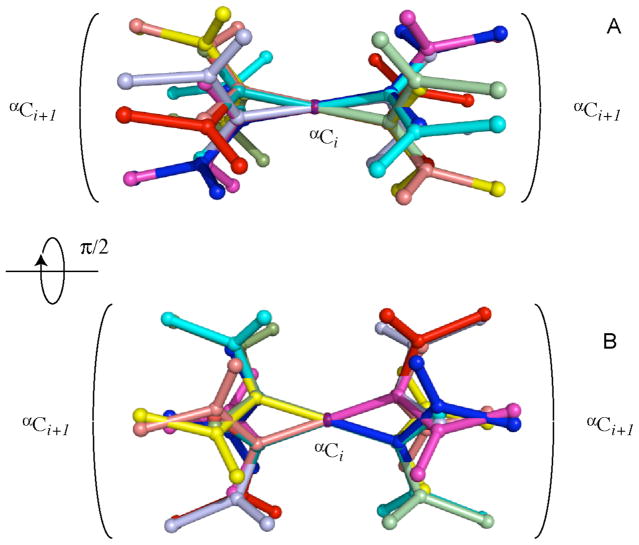
For a structural motif that has no chiral center, which is the case when all vectors lie in the same plane, there is no such restriction and all 8 sign combinations yield allowed solutions. Interestingly, generally there exist 8 additional solutions that lie in the same planes as the solutions of the first set but whose vector components have orientations that differ from the ones of the first 8 solutions, which is illustrated in Fig. 1. These additional solutions flip the planes upside down (e.g. by a 180° rotation about an axis that lies in the plane). Therefore, in the absence of any in-plane symmetry the new solutions cannot be aligned with respect to the old solutions by rotation about an axis orthogonal to the plane.
Figure 1.
Example of sixteen orientations of a peptide plane that are found to be in agreement with a single set of residual dipolar couplings. Cartesian coordinates associated with this example are given in the Supporting Information (Table S1), along with associated RDC values.
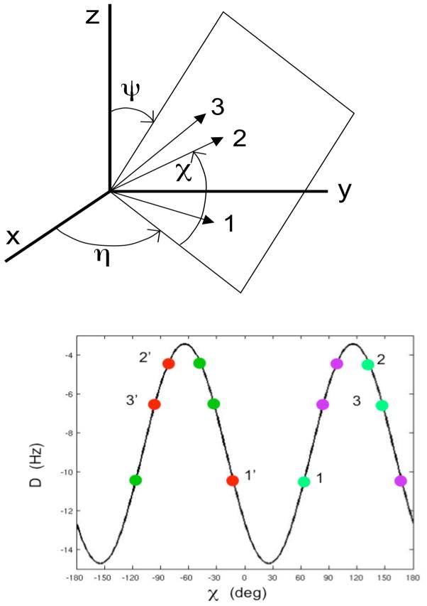
These alternative solutions can be constructed as follows. We consider a plane P depicted in Figure 2A with in-plane vector orientations specified by the three angles (η,ψ,χ) defined in the Figure that can be expressed using standard trigonometry by
Figure 2.
Reverse plane orientations consistent with residual dipolar couplings (RDCs) of three coplanar vectors 1, 2, 3 measured in a single alignment medium with non-zero rhombicity. (A) Definition of angles (η,ψ,χ) that define in-plane vector orientation with respect to alignment frame (x,y,z). (B) For an alignment tensor with Da = 10 Hz and R = 0.35, the four solutions for vector orientations that lie in the same plane are indicated by 4 different colors: the red and magenta solutions are related to each other by a Δχ = 180° in-plane rotation. The two sets of solutions (red/magenta vs. green) are related to each other inverting χ followed by a shift δ, i.e. χ → − χ − δ where δ is defined by Eqs. (2) – (6) as illustrated for vector sets 1, 2, 3 and 1′,2′,3′.
| (2) |
where χ defines the vector orientation within plane P, η is the angle between the intersection of plane P with the xy plane of the alignment frame and the x axis, and ψ is the tilt angle of plane P with respect to the z-axis of the alignment frame. The dipolar couplings can then be expressed as a function of (η,ψ,χ) by insertion of equation (2) into equation (1):
| (3a) |
or
| (3b) |
where , and .
It can be shown that there exists a suitable axis lying in plane P so that a 180° rotation about this axis of the in-plane dipolar vectors yields additional solutions. This is equivalent to demonstrating that a constant offset δ exists that depends on (η,ψ) so that
| (4) |
Insertion of equation (3) into equation (4) yields
| (5) |
Equation (5) is indeed fulfilled for arbitrary angles χ, if δ fulfills
| (6) |
where the 2 solutions for δ = arctan(B A) are 180° shifted with respect to each other as displayed in Figure 2B.
In summary, if for a rhombic alignment tensor (R ≠ 0) an internally rigid planar structural motif fulfills a given set of RDCs then there generally exist no fewer than 16 distinct solutions. The 16 solutions cluster into 4 groups where the 4 solutions of each group lie in the same plane, i.e. each group shares the same (parallel or antiparallel) normal axis to the plane. In the alignment frame, each of these axes points toward one of the 4 upper quadrants. The 4 solutions of each group cluster into 2 subgroups where the solutions in the subgroups are related to each other by a 180° rotation about the normal axis. The subgroups are related to each other by a 180° rotation about the axis that intersects the plane P and the xy plane of the alignment frame followed by a rotation about the normal by −δ.
It further follows that a chiral motif consisting of dipolar vectors within a plane and dipolar vectors orthogonal to the plane has the same 16 solutions as the planar system without violating the chirality constraint. A systematic description of all solutions in terms of rotations about the 3 Euler angles is given in the following sections.
Determination of solutions from experimental data
To determine all possible orientations of an internally rigid molecular fragment based on RDC data we find it convenient to use internal angular coordinates:
| (7) |
Equation (7) expresses dipolar couplings in terms of normalized spherical harmonics functions of rank 2, , where (θi,φi) are the polar angles that belong to the corresponding vector ei in the alignment tensor frame. For a set of vectors ei one can always define a rotation that rotates the vectors from their initial coordinates in a fixed frame of reference to the frame of the alignment tensor where their coordinates are (θi,φi) and their residual dipolar coupling is given by equation (7). Such a rotation can be described by using the Wigner matrices25 with elements that depend on the Euler angles (α, β, γ). Application of this rotation to equation (7) yields:16
| (8) |
After simplification the following expression for the normalized residual dipolar coupling is obtained
| (9a) |
where Bk are geometric functions that relate the molecular frame to the alignment frame
| (9b) |
with ((α, β, γ) corresponding to the rotation angles according to the zxz convention (i.e. 1st rotation by α about z-axis, 2nd rotation by β about x-axis, 3rd rotation by γ about z-axis) and the represent the dipolar vector orientations in the molecular frame
| (9c) |
The linear system of equations can be solved by linear least-square minimization, e.g. using singular value decomposition (SVD), if there are at least 5 different dipolar couplings available. This relates to the fact that generally 5 RDCs are necessary to determine the alignment tensor.26 Here, we assume that the alignment tensor magnitude Da and rhombicity R are already known. Therefore, fewer than 5 RDCs allow establishment of the orientations of a structural motif as is discussed below.
Equation (9) reflects the fact that, when one knows the coordinates of a set of vectors and their normalized residual dipolar couplings, one can extract coefficients Bk that contain the information about the rotational transformation of these vectors to their correct orientations in the alignment frame. The associated Euler angles and rhombicity R can be extracted from these coefficients as follows:
-
If R = 0:
(10a) which means that there is an infinite number of solutions due to the axial symmetry of the alignment tensor.
- If R ≠ 0:
(10b)
With the following allowed ranges for the Euler angles, the four-fold degeneracy in orientation, leading to 4 rotations having the same residual dipolar couplings, is compiled in Table 1:
| (11) |
Table 1.
4-fold degeneracy of fragment orientation.
| Solution | Euler angles | ||
|---|---|---|---|
| 1 | α | β | γ |
| 2 | α | β | γ + π |
| 3 | α+π | π − β | −γ |
| 4 | α+π | π − β | −γ + π |
Hence, for the general case of N vectors, equation (10b) defines the Euler angles describing the rotation that transforms these vectors from a molecular frame of reference to the alignment frame.
In the presence of symmetries in the molecular fragment under consideration, some of the coefficients Bk can be undetermined, which leads to additional allowed fragment orientations. In the following section, we consider special cases that are relevant for applications to proteins and peptides.
Peptide Plane
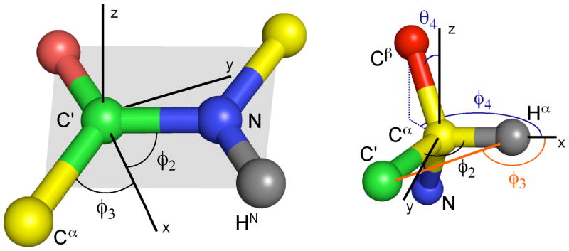
The situation where all dipolar vectors lie in the same plane has already been mentioned above. This situation is commonly encountered in practice with the peptide plane in proteins and nucleic acid bases being the most prominent examples. It is convenient to align the xy plane of the coordinate system with the molecular plane so that all in-plane vectors have . Here and in the following section ideal geometries and noise-free RDC data are assumed. As a consequence, in equation (9c) coefficients and are zero and hence B4 and B5 are undetermined, which increases the number of possible solutions. Figure 3A shows the angles that define the peptide plane motif. We use a minimum of 3 vectors including N HN, N(i) - C′(i−1) and C′(i−1) Cα(i−1) whose polar coordinates are:
| (12) |
Figure 3.
Definition of angles for (A - left) 3 vectors that lie in the peptide plane and (B - right) 4 vectors of the chiral amino acid Cα center at the junction between adjacent peptide planes.
Equation (9a) then leads to:
| (13) |
From the first 3 equations one obtains for B1, B2 and B3
| (14) |
which according to equation (10b) leads to Euler angles (α, β, γ). Since in equation (9c) coefficients , B4 and B5 do not impose any restriction. Therefore, for R ≠ 0 there are additional solutions (α′, β′, γ′), which are consistent with the first three equations of (9b) and (9c):
| (15) |
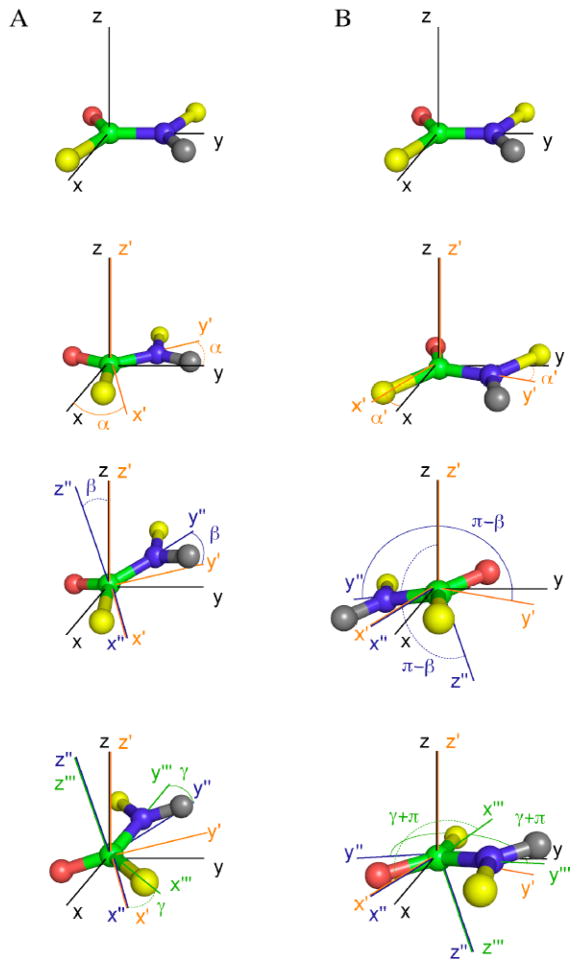
The (α, β, γ) set and the (α′, β′, γ′) set are both 8-fold degenerate as listed in Table 2. The complete set of peptide plane orientations satisfying the RDCs is then 16, consistent with the Theory section. Only in special cases, some of these solutions will coincide such that the effective degeneracy can coalesce to ≤8. The two sets of solutions are related to each other by a rotation about an axis that lies in the peptide plane as discussed above (see also Figures 1 and 2). Figure 4 provides a step-by-step description of Euler angle rotations for the two sets of solutions. The structure determination protocol Meccano6 developed for the determination of protein backbone conformation using only RDCs measured in two different alignment media, exploits the result that the 16 fold degeneracy is reduced to a 2-fold degeneracy under these circumstances.
Table 2.
16-fold degeneracy, solutions 9 to 16 are identical to 1 to 8, except for replacing (α, β, γ) by (α′, β′, γ′) as defined in the text.
| Solution | Euler angles | ||
|---|---|---|---|
| 1 | α | β | γ |
| 2 | α | β | γ + π |
| 3 | α+π | π − β | −γ |
| 4 | α+π | π − β | −γ + π |
| 5 | α+π | β | γ |
| 6 | α+π | β | γ + π |
| 7 | α | π − β | −γ |
| 8 | α | π − β | −γ + π |
Figure 4.
Step by step illustration of Euler angle rotations of one vector according to 2 sets of Euler angles (α, β, γ) (left column) and (α′, β′, γ′)(right column).
Amino acid Cα chiral center
By using a suitable choice of the initial coordinates, equation (9a) can be solved analytically in the case of a non-planar motif. We now demonstrate this result for the Cα chiral center of an amino acid (Figure 3B) using the 4 one-bond residual dipolar couplings: Cα – Hα,Cα – Cβ, Cα – C′ and C′ – Hα.
We assume the Cα chiral center to have perfect tetrahedral bond geometry with vector 1 being the Cα – Hα vector along the x axis. The internal coordinates are (Figure 3B):
| (16) |
Equation (9) then leads to:
| (17) |
One can readily extract B1, B2 and B3 from the C′ – Cα – Hα plane using equation (14) and the associated Euler angles (α,β,γ) according to equation (10). Moreover, equation (9b) leads to:
| (18) |
with solutions:
| (19) |
Thus, there are generally two solutions for B4 and B5. However, since the Euler angles are known, B4 and B5 are also determined by equation (9b) and Table 2, which permits identification of the solution that is consistent with the C′ – Cα – Hα RDC information. This procedure yields the 4 sets of unique Euler angles that describe the orientations of the chiral motif that are consistent with the 4 RDCs. As noticed above, for θ4 = 0 (vector normal to the plane) the 16 solutions are valid even though it is a chiral motif since b4 = 0, and b5 = 0 and B4 and B5 do not enter equation (17).
When the alignment tensor is known, the above formulas allow determination of all fragment orientations consistent with the RDC set. Because these fragments are part of a larger molecular structure to which they are chemically bonded, additional constraints apply such as bond angle and dihedral angle constraints. Moreover, additional information may be available about internuclear distances (from NOEs and trans-hydrogen bond scalar J-couplings) and dihedral angles (from scalar 3J-couplings and chemical shifts) as discussed in the following section.
3. Application to biomolecular structure determination
By far the most prevalent use of experimental RDCs is found in their application to the refinement of structures whose global architecture is already defined, for example from distance constraints derived from NOESY experiments. Restrained molecular dynamics calculations are thus routinely used to refine the conformations of proteins and nucleic acids using RDC constraints typically measured in a single alignment medium only. In order to assess the implications of the analytical solutions derived above on commonly applied protocols we have undertaken a series of calculations using both simulated and experimental data.
Characterization from simulation
The possible manifestation of the 16 RDC-consistent orientations available for any single planar element using data from one alignment medium has been simulated using RDC-restrained molecular dynamics calculations performed using the program Sculptor27 under the following conditions:
-
Peptide plane RDCs (N-HN, C′-Cα, N(i)- C′(i−1) and HN -C′(i−1)) were simulated from the known structure of protein GB328 using a maximally rhombic alignment tensor. Distances were also simulated between all HN and Hα in the protein, and all distances less than 5 Å were then used as simulated NOE restraints with lower and upper limits of 0 Å and 6 Å, respectively. The structure was then subjected to a restrained molecular dynamics simulation with only the NOE restraints applied followed by refinement using both simulated NOEs and simulated RDCs. Both simulations used Cartesian dynamics with a timestep of 0.3 fs, with a sampling period of 8 ps at 1000 K, followed by slow cooling to 100 K over 12 ps and subsequent energy minimization. The alignment tensor eigenvalues and eigenvectors were allowed to evolve during the whole period, resulting in accurate reproduction of the original tensor.
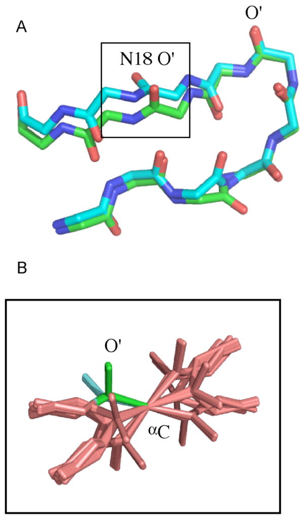
Two low energy structures are shown in Figure 5 that agree equal well with the simulated RDCs. Two planes are seen to have peptide plane orientations that fulfill the RDCs and neither violate tetrahedral geometry nor the loose distance restraints. In order to check whether all these orientations are RDC-consistent as described by equations (10), the RDCs from the N18/G19 plane were used as restraints to determine the orientation of a single, free peptide plane using the known alignment tensor from the simulation. The results of 100 repeated calculations for which RDC energy violations were equivalent and negligible are shown in Figure 5B. The complete set of 16 peptide plane orientations is visibly present, with two of these corresponding to the two orientations shown in Figure 5A. Clearly both covalent and non-bonded terms in the force field, as well as additional experimental restraints, will impose additional restrictions on the physical viability of any of these solutions. In particular orientations that invert the direction of the peptide chain are highly unlikely and are excluded (e.g. on the basis of the position of the subsequent amino acid). We note, however, that four peptide plane orientations have similarly positioned Cα atoms, underlining the real possibility that wrong orientations can be found for peptide planes.
-
In the second example, experimental distance constraints have been taken29 from the Sulfite Reductase Flavodoxin-like Domain SiR-FP18 (comprising 1114 NOESY-derived distance restraints, 119 hydrogen bond distance restraints based on trans-hydrogen bond 3JNC couplings and accurate dihedral angle restraints from 13C chemical shifts), together with simulated peptide plane RDC data from imposed rhombic alignment tensors (tensors 1 and 2) using a known structure determined using the NOESY, dihedral angle and hydrogen-bond distance restraints from randomized initial coordinates.29 RDCs were also simulated from a third, differently oriented alignment tensor (tensor 3) for purposes of comparison. The use of the third tensor allows for straightforward identification of incorrently oriented planes. These three tensors are linearly independent, as gauged by the scalar product of the tensor elements (Table 3). The same restrained molecular dynamics protocol was applied (see simulation 1) to the refinement of the distance-only derived structures. Five calculations were performed with the following active RDCs:
No RDCs used in the structure refinement
N-HN RDCs simulated from tensor 1 used in the structure refinement
Four RDCs from the peptide plane (N-HN, C′-Cα, N(i)- C′(i−1) and HN -C′(i−1)) simulated from tensor 1 used in the structure refinement
Four RDCs from the peptide plane (N-HN, C′-Cα, N(i)- C′(i−1) and HN -C′(i−1)) simulated from tensor 1 and tensor 2 used in the structure refinement
N-HN RDCs simulated from tensor 1 and tensor 2 used in the structure refinement
Figure 5.
RDC-consistent orientations of peptide plane units produced from RDC-restrained molecular dynamics calculations. (A) Two different RDC-consistent orientations of peptide unit N18-G19 in protein GB3. Data were simulated from a known tensor and subsequently used as restraints, in addition to loose distance restraints between backbone protons (see text). The two structures agree equally well with RDC and distance data as well as tetrahedral geometry. (B) Peptide plane data from peptide plane N18-G19 were used as restraints using the same protocol as in A with CNS-Sculptor to determine the possible orientations of the isolated plane. All 16 solutions predicted from equations 16–18 are shown here. Two of these (the green and the cyan conformations) correspond to the two shown in Panel A. Note that 4 solutions have very similar Cα positions at either end of the plane, illustrating the possibility of finding false minima.
Table 3.
Alignment tensors used to simulate RDCs from SiR-FP18 (1–3) and experimental tensors from bacteriophage and steric alignment media (A, B)
| Da(Hz) | R (10−4) | α(°) | β(°) | γ(°) | |
|---|---|---|---|---|---|
| Tensor 1 | 23 | 0.65 | 45.0 | 0.0 | 45.0 |
| Tensor 2 | 23 | 0.65 | 0.0 | 45.0 | 45.0 |
| Tensor 3 | 23 | 0.65 | 60.0 | 60.0 | 60.0 |
| Tensor A | −21.5 | 0.63 | 84.6 | 107.0 | 117.4 |
| Tensor B | −24.2 | 0.52 | −149.8 | 153.1 | −130.2 |
Structural ensembles were selected on the basis of their agreement with distance and RDC restraints.
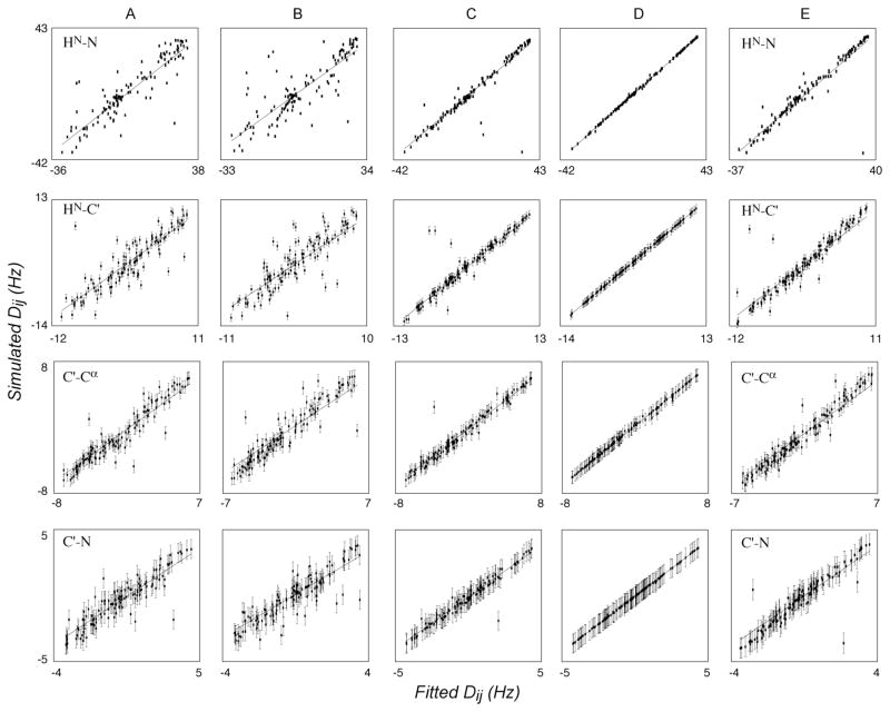
The final ensemble of RDC-refined structures from calculations 2 to 5 are all in close agreement with the respective active RDCs from tensors 1 and 2. These lowest energy (combined experimental energy term associated with RDCs and distance restraints) structures were compared with the RDCs from tensor 3 by fitting the vector orientations of the four RDCs (N-HN, C′-Cα, N(i)- C′(i−1) and HN -C′(i−1)) to an optimal alignment tensor. This provides a simple means to identify correctly and incorrectly oriented planes. The correlation of simulated and calculated RDCs to the best fitting tensors are shown in Figure 6 for typical members of the optimal ensembles for calculations A through E.
Figure 6.
Sampling of RDC-consistent peptide plane orientations using simulated RDCs. Best-fit correlations of RDCs simulated from tensor 3 (Table 3) when fit to optimal alignment tensors determined using structures refined using data from tensors 1 and 2. (A) No RDCs used in the refinement. (B) Only N-HN RDCs from tensor 1 used in structure refinement. (C) Four peptide plane RDCs from tensor 1 used in structure refinement. (D) Four peptide plane RDCs from tensors 1 and 2 used in structure refinement. (E) Only N-HN RDCs from tensors 1 and 2 used in structure refinement.
Importantly, it can be seen that there is no visible improvement between refinement against a single vector from a single alignment medium with respect to using no RDCs. This has previously been noted (Ad Bax, personal communication), but is strikingly clear from correlations in Figures 6A and 6B. We note here that using a single set of N-HN RDCs, it is not always possible to determine the alignment tensor to any accuracy. Alignment tensors are normally determined simultaneously during structure refinement, either using discrete sampling of different combinations of the axial and rhombic components of the tensor or by allowing the tensor eigenvalues to float. The latter approach is used here, and while we find that the eigenvalues are sometimes correctly chosen, they can also be wrong, and the target function of the ‘active’ constraints does not reflect this. For example one of the best structures (on the basis of experimental and physical violations) has an axial tensor component of 31 Hz rather than the value of 23 Hz that was used to simulate the data.
In order to investigate this effect in more detail we have calculated the backbone rmsd over ensembles calculated with no RDC information and compared this to the ensembles calculated using 1 full N-HN RDC set, 1 full set of 4 RDCs per peptide plane and 2 full sets of peptide plane RDCs. The overall rmsd falls slightly (0.61 compared to 0.68Å) when N-HN RDCs are introduced. This information is presented in the Supporting Information on a per-residue basis (Figure S2 Supporting Information). In this specific case local and global structure of SiR FP18 are well defined by the experimental NOE and dihedral angle restraints, as demonstrated by the already low rmsd, and under these conditions, refinement against a single set of N-HN RDCs provides only minor improvement, and does not necessarily better orient the N-HN vectors compared to the RDC-free refinement. In the light of the high degeneracy of vector orientations that are consistent with a given RDC value, it should not surprise that refinement against a single set of couplings provides negligible improvement. Exceptions are conceivable, however, for example when the mutual orientations of helical elements are poorly determined due to the sparsity of long-range NOEs. In such cases, the combination of N-HN vectors from multiple sites may provide a better determination of the relative orientations of the helices.
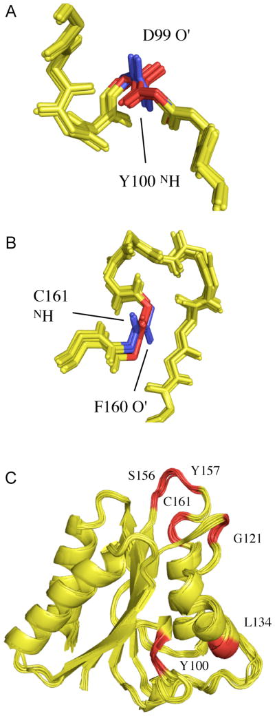
Beyond a single vector, 2 vectors (results not shown) and 4 vectors from a single alignment medium define a planar element (Figure 6C) that reproduces RDCs from tensor 3 for the vast majority of sites, and results in more precisely defined backbone conformations (rmsd 0.39Å). However the presence of alternative peptide plane orientations was also detected by large local violations of the third set of RDCs (Figure 6C). These are visible as clear outliers in the panels, especially for the N-HN and HN -C′(i−1) RDCs. Investigation of these sites reveals that each case corresponds to one of the alternative fifteen orientations of the planes described above. Two such cases are shown in Figure 7A,B. For peptide plane D99/Y100, two orientations of the plane can be identified. Both are in agreement with the available distance restraints and tetrahedral geometry at the Cα positions. The case of F160/C161 (Figure 7B) illustrates that the orientation of the plane is almost inverted between the two solutions, with the hydrogen bonding moieties positioned on different sides of the peptide chain. Again no violations of the experimental NOEs are found. The positions of the sites in the protein where two orientations are observed are shown in Figure 7C, illustrating the fact that while such ambiguous peptide plane orientations are more likely to occur in loop regions, due to the generally lower NOE constraint density, they can also occur in regular secondary structural regions. The C′-Cα and N-C′ vectors are less sensitive to the presence of incorrect orientations, probably because the overall fold, determined by distance information, essentially defines the position of the Cα atoms, such that the degrees of freedom available to these vectors are more restricted than the vectors involving the HN atom.
Figure 7.
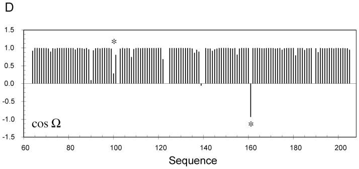
RDC-consistent orientations of peptide plane units produced from RDC-restrained molecular dynamics calculations using experimental distance restraints from Sulfite Reductase Flavodoxin-like Domain and simulated RDC data from a single alignment tensor. (A) The 20 structures in the lowest experimental energy ensemble sample two RDC-consistent orientations of peptide unit D99/Y100 that are in agreement with the distance constraints. The blue orientation is the correct orientation. (B) The 20 structures in the lowest experimental energy ensemble sample two RDC-consistent orientations of peptide unit F160/C161 that are in agreement with the distance constraints. The blue orientation again shows the correct orientation. (C) Sites of Sulfite Reductase Flavodoxin-like Domain (in red) where two RDC-consistent orientations are observed. (D) Display of cos(Ω) for one of the structures shown in Panels A–C, where Ω is the angle between the peptide planes in the structure of interest and the target, or known structure (see text). The position of peptide planes 99–100 and 160–161 are shown with an asterisk.
It is also useful to represent the misorientations using a metric that directly relates to the molecular structure. We have therefore calculated the cosines of angles between vectors in each plane, and the angle (Ω) between the planes of interest and planes in the target, or known structure. The quantitiy cos(Ω) is shown for each plane for one of the structures present in the ensemble illustrated in Figure 7 (Figure 7D). While for the majority of sites we see that the orientation is correctly determined (cos(Ω)≈ 1) for other sites the orientation is clearly different, indicating that the plane populates one of the possible equivalent orientations. The cases of orientational degeneracy illustrated in Figures 7A and 7B are both present and are indicated by asterisks. In the case of plane 160–161 the large angle (>90°) between the correct and incorrect conformations results in a negative value of the cosine.
Not surprisingly, calculations carried out using data from both alignment tensors (Figure 6D) eliminates all of the spurious minima, leaving only the native orientation. The rmsd of the backbone conformation compared to the average structure falls to 0.36 Å compared to 0.39Å for a single set of couplings (Figure S2 in Supporting Information). Use of RDCs from two differently aligned tensors will indeed reduce the peptide plane orientational degeneracy from 16 to 2, which is the correct plane orientation and its inverse.
We have also compared the validity of plane orientations refined using only N-HN RDCs measured in two alignment media (Figure 6E). This again results in isolated occurrences of incorrect orientations of the N-HN vectors. It is important to note that in each case the RDCs used for refinement are essentially in perfect agreement with the structures. Cross validation of the plane orientations using other vectors within the plane do not readily reveal that these orientations are in fact incorrect. It is therefore hard to detect this type of local structural errors in the absence of additional orientational information.
Manifestation in experimental ensembles of RDC-refined structures
Identification procedure of wrong peptide plane orientations by cross-validation relying on RDCs from different alignments can be directly applied to experimental data. Naturally, demonstration of such effects will also depend on experimental noise in both the ‘active’ data set, and in the data set used to identify the incorrect equivalent orientations. For this purpose, we have applied the same structure refinement protocols using two high quality experimental RDC data sets from SiR FP18 in combination with experimental NOESY derived distances.
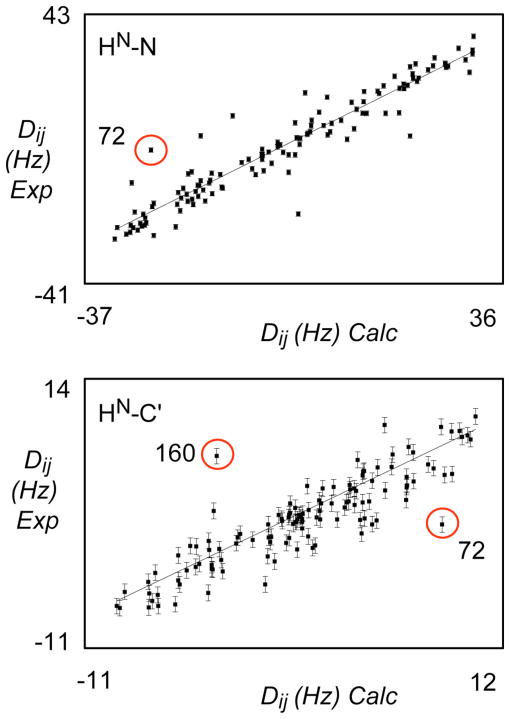
Alignment medium A (bacteriophage) is expected to align on the basis of electrostatic repulsion, while alignment medium B (PEG/hexanol mixture) is expected to align on the basis of steric repulsion. The resulting alignment tensors have previously been shown to be significantly different (Table 3). The structural ensembles resulting from refinement with respect to media A and B show similar behavior to that observed from the simulated data sets: outliers are observed when compared to the ‘passive’ data sets that are not used in the refinement. In Figure 8 we show correlations with respect to N-HN and C′-HN RDCs from typical members of the two ensembles.
Figure 8.
(A) Best-fit correlation of experimental N-HN RDCs from alignment medium B when fit to optimal alignment tensors determined using structures refined using experimental N-HN, C′-Cα and C′-HN RDCs data from alignment medium A. Correlation from a typical structure is shown from the ensemble best-fitting the active data set (alignment medium A, bacteriophage). A circled outlier corresponds to one of the sites populating two RDC-consistent orientations with respect to these data (see Figure 9).
(B) Best-fit correlation of experimental C′-HN RDCs from alignment medium A when fit to optimal alignment tensors determined using structures refined using experimental N-HN, C′-Cα and C′-HN RDCs data from alignment medium B. Correlation from a typical structure is shown from the ensemble best-fitting the active data set (alignment medium B, alcohol-based alignment). Circled outliers corresponds to sites populating two RDC-consistent orientations with respect to these data (see Figure 9).
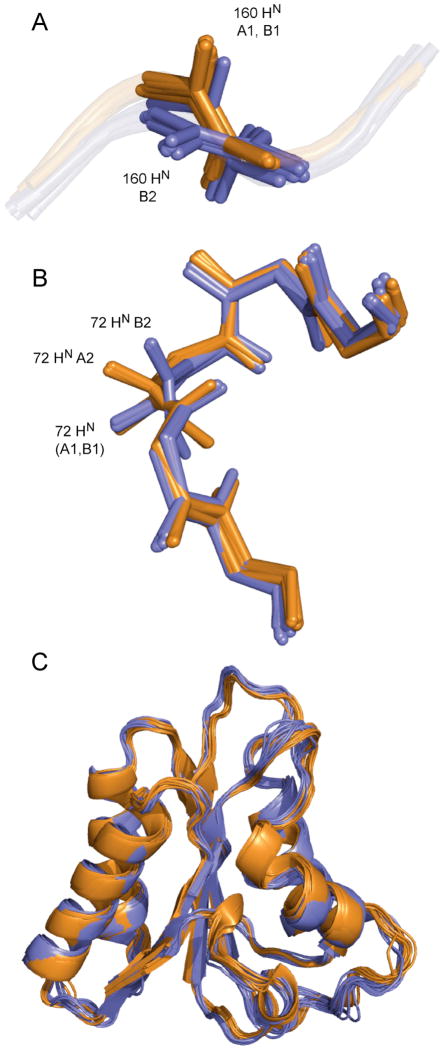
Investigation of the structural ensembles reveals that the observed outliers indeed correspond to sites where both correct and incorrect RDC-consistent orientations are sampled. Figure 9 illustrates two such sites. In the case of the plane associating amino acids 158–159, two orientations are found from the refinement with respect to data from medium B, while a single orientation is found in the ensemble refined with respect to data from medium A.
Figure 9.
(A) Peptide plane 159–160 shows two orientations in the structural ensemble determined using data from alignment medium B (blue). Two minima B1 and B2 are indicated. Data from alignment medium A (orange) define a single orientation (A1).
(B) Peptide plane 71–72 shows two orientations in the structural ensemble determined using data from alignment medium B (blue: minima B1 and B2). The structural ensemble determined using data from alignment medium A (orange) also show two orientations (A1 and A2). The common orientation is correct.
(C) Comparison of the structural ensembles refined using RDCs from media A (orange) and B (blue).
The incorrect orientations in the ‘B’ ensemble violate RDCs from medium A as shown in Figure 8. In the case of the plane associating amino acids 71–72, two orientations are found from the refinement with respect to data from both media (Figure 9). Of course only the common orientation is correct, while the incorrect orientations violate RDCs from the unused medium in both cases as shown in Figure 8. In all cases, the structures in the final ensembles reproduce the active RDCs well. We note that these ensembles are very similar with respect to global rmsd measurements (0.52±0.08 and 0.64±0.07 Å) compared to the respective means, and mostly differ in terms of local structure resulting from ambiguous definition of individual peptide plane orientations (Figure 9C).
Implication for structure refinement protocols
Both simulated and experimental data therefore indicate that ambiguous orientations predicted from the analytical descriptions derived above can appear in representative ensembles of structures refined using a single set of RDCs. Their presence is somewhat random, assuming that the correct orientation is equally likely, and that other experimental data as well as covalent and non-covalent restraints do not discriminate between the solutions. In this case the ensemble can contain two or more families of similarly oriented planes. Use of additional RDC restraints from the tetrahedral junction, use of more accurate dihedral angle restraints (e.g. from TALOS), or use of more precise NOEs distance information, may reduce the possibility of sampling RDC-consistent, but wrong peptide plane orientations. In this context it is, however, important to note that the distance information measured from SiR FP18 was both relatively complete, including experimentally determined hydrogen-bonding restraints and NOEs extracted from high-resolution NOESY spectra. If one finds numerous sites where multiple orientations are observed under such favorable refinement conditions as illustrated using both noise-free simulated and experimentally measured RDCs, it would be surprising if such cases were not common in standard RDC refinement studies.
A number of additional factors can contribute to the precision of structures refined against RDCs. These include the true geometry of local structural elements that are often constrained to adopt a common optimal geometry. A second source of potential error lies in the supposition that a static model can appropriately describe the experimentally measured parameters. Dynamic averaging however can significantly affect measured RDCs16,30–34 so that refinement against motionally averaged RDCs will be expected to compromise the orientational information present in the final structure. Hence, the analysis presented here primarily applies to amino acids that are part of structured and motionally confined regions of the polypeptide chain.
4. Conclusions
The relationship between a set of RDCs and the associated internuclear vector orientations expressed in an arbitrary molecular frame is determined by the 5 parameters Bk which are obtained by a linear least-squares fit. Conversion of the Bk parameters to the 3 Euler angles that define the orientation of the molecular fragment in the alignment frame must take into account that there are multiple solutions due to the symmetry of the alignment tensor and possible symmetries, such as planarity, of the fragment itself. Analytical expressions have been introduced here for the complete set of non-equivalent Euler angles. These relationships, together with bonding constraints, are directly applicable to the reconstruction of biomacromolecular structures from RDCs. Even though this analysis assumes idealized local geometry, it holds interest in methods for the scaffolding of protein backbone structures.
Application of the derived expressions to the description of peptide plane orientations demonstrates that for nonzero rhombicity there are generally 16 non-equivalent solutions. Because some of the wrong solutions can have similar orientations as the correct solution, their detection can be difficult, directly affecting the validity and resolution of a protein structure determined by standard RDC-assisted refinement. In terms of standard practices for protein structure refinement, we show that the existence of 16 different RDC-consistent peptide plane orientations can result in incorrect local plane orientations, even in the presence of extensive long-range NOE distance information. This has immediate implications for the correctness and resolution of protein and nucleic acid structures that are refined against a single set of RDCs.
Supplementary Material
Acknowledgments
This work was supported by the NIH (grant R01 GM 066041) and NSF (grant 0621482) to R. B. and through EU-NMR JRA3 project number: RII3-026145 and ANR NT05-4_42781 to M.B.
Footnotes
Supporting Information Available
Cartesian coordinate representation of 16 distinct solutions for peptide plane orientations. Backbone RMSDs of Sulfite-Reductase Flavodoxin-like Domain for different RDC refinement protocols. This material is available free of charge via the Internet at http://pubs.acs.org.
References
- 1.Bax A, Kontaxis G, Tjandra N. Nucl Magn Reson Biol Macromol, Pt B. 2001;339:127–174. doi: 10.1016/s0076-6879(01)39313-8. [DOI] [PubMed] [Google Scholar]
- 2.Blackledge M. Progr Nucl Magn Reson Spectr. 2005;46:23–61. [Google Scholar]
- 3.Prestegard JH, Bougault CM, Kishore AI. Chemical Reviews. 2004;104:3519–3540. doi: 10.1021/cr030419i. [DOI] [PubMed] [Google Scholar]
- 4.Tjandra N, Omichinski JG, Gronenborn AM, Clore GM, Bax A. Nature Struct Biol. 1997;4:732–738. doi: 10.1038/nsb0997-732. [DOI] [PubMed] [Google Scholar]
- 5.Delaglio F, Kontaxis G, Bax A. J Am Chem Soc. 2000;122:2142–2143. [Google Scholar]
- 6.Hus JC, Marion D, Blackledge M. J Am Chem Soc. 2001;123:1541–1542. doi: 10.1021/ja005590f. [DOI] [PubMed] [Google Scholar]
- 7.Fowler CA, Tian F, Al-Hashimi HM, Prestegard JH. J Mol Biol. 2000;304:447–460. doi: 10.1006/jmbi.2000.4199. [DOI] [PubMed] [Google Scholar]
- 8.Mueller GA, Choy WY, Yang DW, Forman-Kay JD, Venters RA, Kay LE. J Mol Biol. 2000;300:197–212. doi: 10.1006/jmbi.2000.3842. [DOI] [PubMed] [Google Scholar]
- 9.Saupe A. Angewandte Chemie - Internat Ed. 1968;7:97. [Google Scholar]
- 10.Ketchem RR, Hu WD, Cross TA. J Cell Biochem. 1993:277–277. [Google Scholar]
- 11.Tycko R, Stewart PL, Opella SJ. J Am Chem Soc. 1986;108:5419–5425. [Google Scholar]
- 12.Opella SJ, Stewart PL. Methods in Enzymology. 1989;176:242–275. doi: 10.1016/0076-6879(89)76015-8. [DOI] [PubMed] [Google Scholar]
- 13.Quine JR, Cross TA. Concepts Magn Reson. 2000;12:71–82. [Google Scholar]
- 14.Mascioni A, Veglia G. J Am Chem Soc. 2003;125:12520–12526. doi: 10.1021/ja0354824. [DOI] [PubMed] [Google Scholar]
- 15.Mesleh MF, Veglia G, DeSilva TM, Marassi FM, Opella SJ. J Am Chem Soc. 2002;124:4206–4207. doi: 10.1021/ja0178665. [DOI] [PMC free article] [PubMed] [Google Scholar]
- 16.Meiler J, Prompers JJ, Peti W, Griesinger C, Brüschweiler R. J Am Chem Soc. 2001;123:6098–6107. doi: 10.1021/ja010002z. [DOI] [PubMed] [Google Scholar]
- 17.Meiler J, Blomberg N, Nilges M, Griesinger C. J Biomol NMR. 2000;17:185–185. doi: 10.1023/a:1008378624590. [DOI] [PubMed] [Google Scholar]
- 18.Moltke S, Grzesiek S. J Biomol NMR. 1999;15:77–82. doi: 10.1023/A:1008309630377. [DOI] [PubMed] [Google Scholar]
- 19.Wang J, Walsh JD, Kuszewski J, Wang YX. J Magn Reson. 2007;189:90–103. doi: 10.1016/j.jmr.2007.08.018. [DOI] [PubMed] [Google Scholar]
- 20.Walsh JD, Wang YX. J Magn Reson. 2005;174:152–162. doi: 10.1016/j.jmr.2005.01.018. [DOI] [PubMed] [Google Scholar]
- 21.Wang LC, Donald BR. J Biomol NMR. 2004;29:223–242. doi: 10.1023/B:JNMR.0000032552.69386.ea. [DOI] [PubMed] [Google Scholar]
- 22.Wedemeyer WJ, Rohl CA, Scheraga HA. J Biomol NMR. 2002;22:137–151. doi: 10.1023/a:1014206617752. [DOI] [PubMed] [Google Scholar]
- 23.Tian F, Valafar H, Prestegard JH. J Am Chem Soc. 2001;123:11791–11796. doi: 10.1021/ja011806h. [DOI] [PubMed] [Google Scholar]
- 24.Skrynnikov NR, Kay LE. J Biomol NMR. 2000;18:239–252. doi: 10.1023/a:1026501101716. [DOI] [PubMed] [Google Scholar]
- 25.Zare RN. Angular Momentum. John Wiley & Sons; New York: 1988. [Google Scholar]
- 26.Losonczi JA, Andrec M, Fischer MWF, Prestegard JH. J Magn Reson. 1999;138:334–342. doi: 10.1006/jmre.1999.1754. [DOI] [PubMed] [Google Scholar]
- 27.Hus JC, Marion D, Blackledge M. J Mol Biol. 2000;298:927–36. doi: 10.1006/jmbi.2000.3714. [DOI] [PubMed] [Google Scholar]
- 28.Bouvignies G, Markwick P, Brüschweiler R, Blackledge M. J Am Chem Soc. 2006;128:15100–15101. doi: 10.1021/ja066704b. [DOI] [PubMed] [Google Scholar]
- 29.Sibille N, Blackledge M, Brutscher B, Coves J, Bersch B. Biochemistry. 2005;44:9086–9095. doi: 10.1021/bi050437p. [DOI] [PubMed] [Google Scholar]
- 30.Tolman JR, Flanagan JM, Kennedy MA, Prestegard JH. Proc Natl Acad Sci U S A. 1995;92:9279–83. doi: 10.1073/pnas.92.20.9279. [DOI] [PMC free article] [PubMed] [Google Scholar]
- 31.Lakomek NA, Walter KF, Fares C, Lange OF, de Groot BL, Grubmuller H, Brüschweiler R, Munk A, Becker S, Meiler J, Griesinger C. J Biomol NMR. 2008;41:139–55. doi: 10.1007/s10858-008-9244-4. [DOI] [PMC free article] [PubMed] [Google Scholar]
- 32.Bernado P, Blackledge M. J Am Chem Soc. 2004;126:4907–20. doi: 10.1021/ja036977w. [DOI] [PubMed] [Google Scholar]
- 33.Bouvignies G, Bernado P, Meier S, Cho K, Grzesiek S, Brüschweiler R, Blackledge M. Proc Natl Acad Sci U S A. 2005;102:13885–90. doi: 10.1073/pnas.0505129102. [DOI] [PMC free article] [PubMed] [Google Scholar]
- 34.Tolman JR, Ruan K. Chem Rev. 2006;106:1720–36. doi: 10.1021/cr040429z. [DOI] [PubMed] [Google Scholar]
Associated Data
This section collects any data citations, data availability statements, or supplementary materials included in this article.


