Abstract
The purpose of this project was to test a surgical navigation tool designed to help execute a surgical treatment plan. It consists of an electromagnetically tracked pencil that is used to mark bone intraoperatively. The device was tested on a precision block, an ex vivo pig mandible and during performance of six endoscopic vertical ramus osteotomies on pig cadavers. The difference between actual pencil position and that displayed by the computer was measured three times each at ten 2 mm holes on the block (n=30 observations) and on the ex vivo mandible (n=11 measurements). Errors between planned and actual osteotomy locations for the cadaver procedures were measured. The mean distance between known and displayed locations was 1.55 ± 0.72 mm on the precision block and 2.10 ± 0.88 mm on the pig mandible. The error measured marking the same point on the block multiple (n=5) times was 0.58 ± 0.37 mm. The mean error on the simulated osteotomies was 2.35 ± 1.35 mm. Osteomark was simple to use and permitted localization of holes and osteotomies with acceptable accuracy. In the future, the device and algorithms will be revised to further decrease error and the system will be tested on live animals.
Keywords: Surgical navigation, marking tool, endoscopic surgery, mandible
Computer-aided navigation was initially developed for neurosurgical operations. Surgical navigation systems allow visualization of an operative site and surgical instruments simultaneously and relate them to the patient’s diagnostic images (e.g. computed tomographic (CT) scans and magnetic resonance imaging (MRI)). Surgical navigation is a powerful tool that has the potential to transfer a surgical plan accurately.
Intraoperative navigation is being used by a variety of surgical specialists such as otolaryngologists, craniofacial and orthopedic surgeons.6, 10, 13, 15 In recent years, oral and maxillofacial surgeons have become increasingly interested in minimally invasive surgical techniques for trauma (endoscopic treatment of subcondylar, zygomatic and orbital fractures), orthognathic surgery (e.g. endoscopic vertical ramus osteotomy, Le Fort I osteotomy, distraction osteogenesis), reconstructive surgery (endoscopic condylectomy with costochondral grafts), salivary gland diseases (sialoendoscopy for sialolithiasis and strictures) and cosmetic surgery.7, 9, 16 The complexity of these procedures requires precise preoperative planning and accurate transfer of the plan to the patient at the time of operation.12
A number of surgical navigation systems are currently commercially available,1, 2, 4 but some of their specific features, developed for other surgical specialties, make them difficult to use for maxillofacial applications. For example, the need for a reference sensor head frame for neurosurgical procedures is cumbersome when doing maxillofacial surgical procedures. Sensors attached to the upper face do not allow tracking of structures on the mandible. The requirement for standard fiducial markers (registration points) to be placed on the patient before preoperative image acquisition is impractical in some situations (e.g. pediatric and trauma patients). The need for large and cumbersome targets on surgical instruments is not acceptable in the small operative fields in maxillofacial surgery and maintaining a line of sight between a tracker camera and the instruments may not be feasible. Currently existing navigation systems are expensive.4–6, 8
The specific aims of this study were to create and evaluate a surgical navigation system (Osteomark) that would be user friendly for the surgeon and operating room staff, that could be used on the mandible, midface and skull and that would not require additional imaging studies or cumbersome headframes and sensors.
Materials and Methods
Osteomark consists of a transmitter, a marking tool, position and reference sensors, tracking electronics, and a computer (Figure 1). The transmitter emits precisely oriented electromagnetic fields that induce currents in receiving sensors. The sensors are 1.3 mm diameter cylinders attached to a cable. A position sensor is placed in the OsteoMark pencil (Figure 2) and a reference sensor is attached rigidly to a tooth or any other convenient, fixed craniofacial point (Figure 3). The signals generated in these receiving sensors are detected by tracking electronics (3D Guidance™, Ascension Technology, Burlington, VT, USA), which compute the position and orientation of each sensor relative to anatomic regions or points of interest. The position information is transmitted to the computer for use in navigation.
Figure 1.
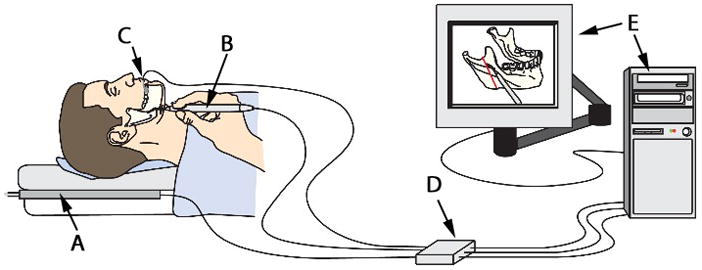
The components of OsteoMark. A transmitter (A), a marking tool (B), a reference sensor attached to a tooth (C), tracking electronics (D) and a computer (E).
Figure 2.
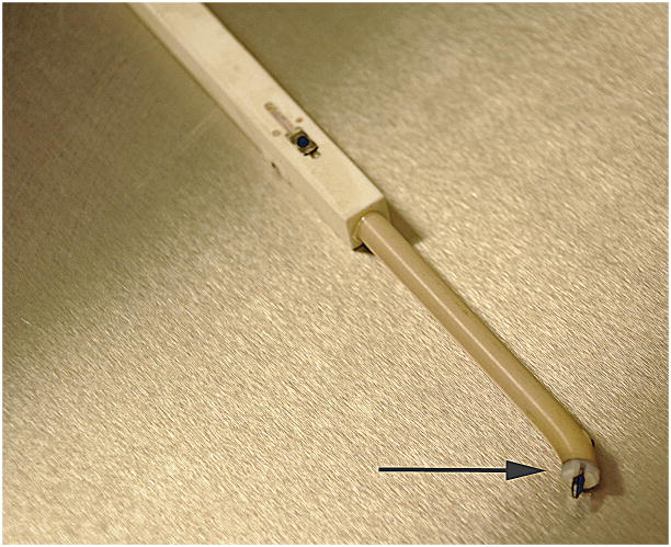
The OsteoMark pencil. A sensor in embedded in the pencil to allow tracking of its position. The tip (arrow) is made of high-impact plastic and has a 45° angled tip.
Figure 3.
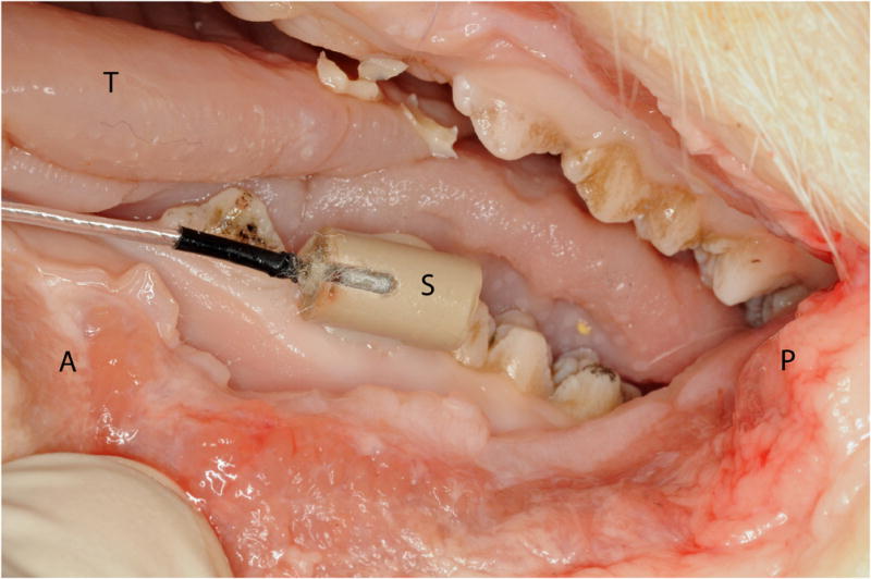
Lateral view of left side of pig mandible with a position sensor (S) rigidly attached to a premolar tooth with composite dental material (A, anterior; P, posterior; T, tongue).
For the purpose of this study, a sensor was placed in a ‘pencil’, used to mark osteotomies. The sensor can be attached to any surgical instrument. The marking pencil is made of high-impact plastic and has a 45° angled tip. The graphite pencil point is fixed in a nylon threaded insert so it can be replaced when it wears during use (Figure 2).
Navigation Procedure
The first step is the registration process. This determines the geometric relationship between the anatomic structures of interest and the 3-dimensional (3D) computer image constructed from the preoperative CT scan. High resolution maxillofacial non-contrast CT scans (GE LightSpeed, Milwaukee, WI, USA) consisting of 1.25 mm axial tomograms were used for the present study. Registration involves two steps. First, the reference sensor is secured to a non-mobile structure on the mandible such as a tooth (Figure 3). Then, the OsteoMark pencil tip, prompted by the computer, is used sequentially to touch pre-selected registration points (fiducial markers) chosen by the surgeon (Figure 4). Registration points may be any anatomic structures that are recognizable on the preoperative image in relation to the reference sensor (e.g. teeth, skin, bone). An indicator on the screen shows each point. Each time a registration point is touched with the pencil, the computer records the location of the position sensor (pencil) and the reference sensor. Using at least three registration points, the computer calculates the physical position of the anatomic structure with respect to the sensors. The computer then uses this registration information to measure the position of the pencil relative to the preoperative CT scan. The patient’s head can be mobilized freely without the need to re-initialize the registration process because the reference sensor is rigidly attached to a tooth.
Figure 4.
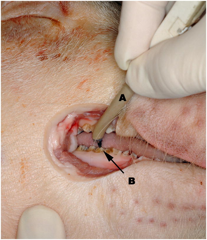
Intraoperative view of right mandible during registration procedure. The Osteomark pencil (A) touches pre determined registration points. Teeth (B) were chosen as registration points in this project.
The image display software is 3D Slicer (Harvard Surgical Planning Lab, Brigham and Women’s Hospital, Boston, MA, USA), a freely available, open-source software platform for visualization, registration, segmentation and quantification of medical data (www.slicer.org).17 Slicer includes a module that allows communication with other programs. A virtual port is opened, allowing exchange of information with a protocol called OpenIGTLink. A stand-alone program (the OsteoMark driver) was developed for this project that communicates with Slicer using OpenIGTLink. Registration points were selected in Slicer. From a module in Slicer the coordinates are communicated to the OsteoMark driver, which also communicates with the 3D Guidance device. Once the first three points are registered, the OsteoMark driver determines the geometric relationship between the image and the actual patient.
Testing the device
Three sets of tests were used to document the accuracy of OsteoMark: registration and measurement accuracy/reproducibility tests with a precision plastic block; registration and measurement accuracy tests with an ex vivo pig mandible; and endoscopic vertical ramus osteotomies performed on 3 Yucatan minipig cadaver heads.
A plastic block perforated with a grid of 2 mm diameter holes was used for the first set of tests. These holes were visible on the computer image representing the block. A 5-point registration procedure was first executed. Randomly selected holes were used as registration points to complete the registration procedure as described above. Following registration, the pencil tip was placed in 10 different holes on the block and the differences (error) in mm between the physical position and location of the screen image of the pen tip were measured using the measuring function of Slicer. This experiment was repeated 3 times for a total of 30 observations (n = 30). An additional test with the block was used to evaluate reproducibility of positioning for each point. The block was registered to the computer model using 5 points. The pencil tip was used to localize each of the 5 points on 5 separate occasions and the error was measured as described above.
A dissected and dried pig mandible was used for the second set of tests. This model was chosen to determine the feasibility of using teeth as registration points. First, the mandible was perforated with multiple holes approximately 2 mm in diameter. The mandible was then scanned and a 3D model was created with Slicer. The reference sensor was secured to a molar tooth using composite dental material. Using anatomical landmarks on teeth (cusp tips and grooves) as registration points, the registration procedure was completed as described previously. The accuracy was then tested with an experiment similar to the one performed on the block. The pencil tip was placed in different holes on the mandible and the difference between the actual and virtual location was measured in millimeters (n = 11 measurements).
Pig cadaver heads were used in the third set of tests. Experiments on the pig cadaver heads were intended to replicate the environment of endoscopic surgery. Endoscopic vertical ramus osteotomy as described by Troulis et al.16 was the experimental procedure. Cadaveric pig heads (n = 3) were scanned and 3D models created with Slicer. Planned osteotomies were marked on the 3D models on each side of the mandibular ramus (n = 6). Teeth were used as reference points and the registration procedure followed the same protocol used for the ex vivo pig mandible. Operations were performed by the same surgeon (CB) on each head.
In brief, a 1.5 cm incision was made at the inferior border of the mandible and blunt dissection, with a fine curved hemostat, was carried to the masseteric fascia. The pterygo-masseteric sling was incised and an optical cavity was created in the sub-periosteal plane over the ramus from the mandibular angle to the sigmoid notch. The Osteomark pencil was then used to mark the osteotomy from the sigmoid notch to the inferior border of the mandible by looking at the computer screen and reproducing the pre planned cut. The osteotomy was performed with a long-shaft reciprocating saw under endoscopic visualization with a 2.7 mm rigid endoscope (30° Hopkins rod lens, Karl Storz Tuttlingen, Germany). After each procedure, the proximal segment of the mandible was dissected out and measured. Measurements were done on the right and left mandibular rami of 3 pig cadaver heads (n = 6 sides) from the posterior aspect of the proximal segment to the osteotomy cut, at 3 different levels, with a digital caliper (n = 18) (figure 5). The same measurements were repeated on the 3D model with the computer software and compared.
Figure 5.
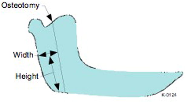
Schematic representation of a pig’s mandible with the osteotomy cut illustrated. The distance from the posterior border of the mandible to the osteotomy was measured at specific heights.
Results
For the precision block tests the mean distance between the known and the displayed locations was 1.92 ± 0.64 mm (0.67–3.21) in the first test (n = 10), 1.36 ± 0.72 mm (0.09–2.21) in the second (n = 10) and 1.38 ± 0.73 mm (0.19–2.61) in the third test (n = 10) (Table 1). The overall mean difference was 1.55 ± 0.72 mm (0.09–3.21) (n = 30). For the reproducibility test, (n=5) the mean error was 0.58 ± 0.37 mm (0.15–1.1) (Table 1).
Table 1.
Accuracy/reproducibility and repeatability tests performed on the precision plastic block. The error represents the difference observed between the known and the virtual position of a 2 mm hole in the block. Errors are reported as mean ± standard deviation (range).
| Precision plastic block | ||
|---|---|---|
| Accuracy/reproducibility | Error | |
| Test 1 (n=10) | 1,92 ± 0,64 (0,67–3,21) | |
| Test 2 (n=10) | 1,36 ± 0,72 (0,09–2,21) | |
| Test 3 (n=10) | 1,38 ± 0,73 (0,19–2,61) | |
| mean | 1,55 ± 0,72 (0,09–3,21) | |
| Reproducibility | ||
| Test 1 (n=5) | 0,58 ± 0,37 (0,15–1,1) | |
For the ex vivo mandible measurements, the mean error between the actual and the virtual locations of the 11 holes on the pig mandible was 2.10 ± 0.88 mm (0.7–3.6) (Table 2).
Table 2.
Accuracy/reproducibility test performed on the ex vivo pig mandible
| Ex vivo mandible | |
|---|---|
| Accuracy/reproducibility | Error |
| Test 1 (n=11) | 2,10 ± 0,88 (0,7–3,6) |
For the pig cadaver head measurements, the mean difference between the cadaver head measurements of the osteotomies and those planned on the 3D model generated by the software was 2.35 ± 1.35 mm (0.6–4.3) (Table 3).
Table 3.
Accuracy/reproducibility tests performed on the cadaveric pig head. An endoscopic vertical ramus osteotomy was performed on each side of three pig heads. Three measurements were done on each osteomized fragments at specific height and width as reported in this table. The error represents the difference between the measurements on the fragments (physical) and the pre planned osteotomy (computer).
| Pig cadaver head | |||
|---|---|---|---|
| Pig 1 | |||
| Left Side | |||
| Fragment Width | |||
| Height | Computer | Physical | Error |
| 30 | 22.7 | 24 | 1.3 |
| 45 | 22.7 | 24.6 | 1.9 |
| 60 | 25.1 | 25.7 | 0.6 |
| Right Side | |||
| Fragment Width | |||
| Height | Computer | Physical | error |
| 30 | 22.5 | 18.3 | 4.2 |
| 45 | 23.9 | 19 | 4.9 |
| 60 | 23.3 | 21.4 | 1.9 |
| Pig 2 | |||
| Left Side | |||
| Fragment Width | |||
| Height | Computer | Physical | error |
| 12.49 | 24 | 20.8 | 3.2 |
| 20.75 | 25.2 | 22.1 | 3.1 |
| 46.25 | 23.4 | 24.6 | 1.2 |
| Fragment Width | |||
| Height | Computer | Physical | error |
| 17.9 | 26 | 26.7 | 0.7 |
| 30.6 | 28.6 | 30.4 | 1.8 |
| 50.7 | 26 | 28.9 | 2.9 |
| Pig 3 | |||
| Left Side | |||
| Fragment Width | |||
| Height | Computer | Physical | error |
| 30 | 26.9 | 26.2 | 0.7 |
| 45 | 23.9 | 23.1 | 0.8 |
| 60 | 28.6 | 24.3 | 4.3 |
| Right Side | |||
| Fragment Width | |||
| Height | Computer | Physical | error |
| 30 | 32.4 | 34.7 | 2.3 |
| 45 | 30.5 | 33.7 | 3.2 |
| 60 | 31.5 | 34.8 | 3.3 |
| mean error | 2.35 ± 1.35 (0.6–4.3) | ||
Discussion
The goal of this project was to develop a simple navigation system to transfer a preoperative treatment plan to the patient during oral and maxillofacial surgical procedures. Surgical navigation relies on synchronization of surgical instruments to the patient’s preoperative images (CT scan or MRI). Four different technologies can be used for intraoperative tracking of instruments and for displaying them on a computer screen relative to the patient’s images: optical, electromagnetic, electromechanical and ultrasonographic.14 Optical trackers are used in most commercially available navigation systems.
When using optical systems, surgical instruments and sensors have to be within the line of sight of the camera in order to be tracked accurately. This is inconvenient when working in a limited surgical field and with the use of endoscopic instruments. Electromagnetic technology is an alternative that does not require the user to maintain a line of sight between the instrument and a camera.11 OsteoMark and several commercially available navigation systems use this technology.
To allow movement of the patient’s head while using surgical navigation, a reference sensor has to be attached to the patient. The reference sensor can be secured to the patient’s soft tissue with plastic straps or adhesives. Although non-invasive, this type of sensor is subject to movement which affects the accuracy of navigation. Other systems require placement of a head frame or a bone anchored sensor. Head frames are cumbersome and not practical for maxillofacial operations, and bone anchored devices are invasive. In addition, the mandible moves separately from the rest of the craniofacial skeleton, so if a mandibular operation is contemplated, the sensor has to be secured to the mandible. In the Osteomark system, a 1.3 mm reference sensor is attached to a mandibular tooth with dental composite material. The sensor is easily removed after completion of the operation, it is not cumbersome, and it can be used on any part of the craniofacial skeleton, including the mandible.
A key component and frequent challenge is registration of the patient to the preoperative image, the basis for navigation. Registration can be achieved by placement of trackable markers on soft or hard tissue. Soft tissue markers, such as discs fixed to the facial skin with adhesives, are subject to movement when CT scans or MRIs are performed. Hard tissue markers, such as occlusal splints, require time for fabrication and rely on patients for correct positioning during image acquisition. While these have proved adequate for many tracking applications, they are not universally applicable. For example, it is often the case that a surgeon does not see a trauma patient prior to imaging. Images with markers are thus not available. Even for elective surgery, this exposes the patient to additional radiation because an additional diagnostic imaging examination may have to be performed to plan the operation. This is particularly problematic with pediatric patients, in whom radiation exposure is a concern.
In contrast, with Osteomark, no markers are necessary when the initial CT images are acquired and the patient can be registered to the software at the time of the operation. Depending on the nature of the procedure, reference sensors may be placed and registered on lower teeth, upper teeth, or both or any other craniofacial landmark.
Strong et al. evaluated the precision of three navigation systems (StealthStation, Medtronics-Xomed, Jacksonville, Florida, USA; Voxim, IVS Solutions, Chemnitz, Germany; VectorVision, Brainlab, Munich, Germany).14 The distance between the actual surgical probe placement and its virtual location on the craniofacial skeleton of cadaveric human heads was measured at 9 different locations for each system. The mean difference observed with the StealthStation system was 1.00 mm, for the Voxim system 1.34 mm and for the VectorVision system 1.13 mm. All systems relied on optical tracking and a headset frame was used as reference sensor.
Casap et al. compared two navigation systems for surgery of the lower jaw.1 The first system, IGI (DenX Advanced Dental Systems, Moshav Ora, Israel), is specifically designed for dental implant placement. This technology uses a tooth-mounted sensor frame, making it more precise for mandibular surgery. The navigation error was calculated to be less than 0.5 mm. The second system, LandmarX system (Medtronix Xomed, Inc, Jacksonville, Florida, USA) uses a headset frame and the mandible has to be immobilized during the operation to allow accurate tracking. The accuracy with this technology was within 3–4 mm.
D’Hauthuille et al. compared intraoperative use of surgical navigation to customized sterolithographic templates for placement of a mandibular distractor.2 On one side of a cadaver head, the osteotomy and the screw placement for the distractor was established with a surgical template constructed on a sterolithographic model. On the other side, the StealthStation navigation system (Medtronics-Xomed, Jacksonville, Florida, USA) was used. With the sterolithographic technology, more preoperative planning was required (1 week) when compared to navigation (15 min) but the operation was shorter (45 min compared to 120 min). This was attributed to the time necessary for the head frame positioning and the registration process. The reference sensor was displaced during the operation, so the entire registration process had to be repeated, prolonging the surgical time. The vector was 3° different from what was planned with the template and 6° with navigation.
Surgical accuracy on the precision plastic block with the Osteomark system described in this paper was 1.55 ± 0.72 mm. This is comparable to existing technology and what is usually agreed to be the range of precision obtained with standard orthognathic surgery.14 The reproducibility when identifying a single point was 0.58 ± 0.37 mm, much better than the accuracy for positioning at different points. This indicates that the error results from systematic characteristics of the registration and location algorithms, not from random variations in the sensor. Improved registration techniques should improve the overall system performance.
The accuracy was not as good on the ex-vivo pig mandible and on the simulated surgery on cadaveric pig heads. This loss of precision may be the consequence of an inadequate registration process. The anatomical landmarks selected on the teeth were sometimes difficult to identify on the 3D CT model of the mandible. This was not an issue on the precision block because landmarks were easily identifiable. In addition, the lack of stiffness of the pen may have contributed to registration inaccuracy.
Although minipig and human mandibles are similar in shape, differences do exist. The pig mandible is 50% larger than that of a human. Errors in angles and scaling that result from imperfect registration produce proportionally larger errors as the test points move farther from the registration points. A smaller error would be expected on a human mandible based on registration alone.
Measurements on the operated mandibles were made from the posterior aspect of the mandible to the osteotomy. The thickness of the saw blade and the fact that the localization of the cut might have been slightly off the marked osteotomy are possible explanations for the diminished accuracy on the animal model. The authors elected to make the measurements from the osteotomy cut instead of the pencil line because it represents a more relevant clinical outcome.
The novelty of the present system is its simplicity. All of the available navigation methods seek to accomplish the goal of executing a computer-based preoperative plan. The purpose of this project was to develop a simpler and less expensive alternative to instrument tracking. Because the pencil is non-metallic, it does not interfere with the field of an electromagnetic tracker. The pencil can thus be tracked by embedding a small electromagnetic sensor in it. This approach is less cumbersome than optical tracking systems that require three reflecting targets on a tracked device and a line of sight between the instrument and the camera.
This approach is built from components that are in use for similar applications, but the authors know of no examples where tracked marking is used for craniomaxillofacial operations. The authors are currently working on a second phase of this project to improve the algorithms for registration and tracking, bringing analytical tools to understand sources of error.3
Acknowledgments
The authors thank Dr. Nobuhiko Hata of the Surgical Planning Laboratory, Brigham and Women’s Hospital, for advising us on the Slicer Software
Funding: This work was supported in part by the AO/Synthes/MGH Fellowship in Pediatric Oral and Maxillofacial Surgery; the Hanson Foundation (Boston, MA); the MGH Department of OMFS Education and Research Fund and by Award Number R43DE019322 from the National Institute of Dental & Craniofacial Research. The content is solely the responsibility of the authors and does not necessarily represent the official views of the National Institute of Dental & Craniofacial Research or the National Institutes of Health.
Footnotes
Competing Interests: None declared
Ethical Approval: Not required
Publisher's Disclaimer: This is a PDF file of an unedited manuscript that has been accepted for publication. As a service to our customers we are providing this early version of the manuscript. The manuscript will undergo copyediting, typesetting, and review of the resulting proof before it is published in its final citable form. Please note that during the production process errors may be discovered which could affect the content, and all legal disclaimers that apply to the journal pertain.
References
- 1.Casap N, Wexler A, Eliashar R. Computerized navigation for surgery of the lower jaw: comparison of 2 navigation systems. J Oral Maxillofac Surg. 2008;66:1467–75. doi: 10.1016/j.joms.2006.06.272. [DOI] [PubMed] [Google Scholar]
- 2.d’Hauthuille C, Taha F, Devauchelle B, Testelin S. Comparison of two computer- assisted surgery techniques to guide a mandibular distraction osteogenesis procedure. Technical note. Int J Oral Maxillofac Surg. 2005;34:197–201. doi: 10.1016/j.ijom.2004.04.001. [DOI] [PubMed] [Google Scholar]
- 3.Danilchenko A, Fitzpatrick JM. General approach to first-order error prediction in rigid point registration. IEEE Trans Med Imaging. 2010 Mar;30(3):679–93. doi: 10.1109/TMI.2010.2091513. Epub 2010 Nov 11. [DOI] [PMC free article] [PubMed] [Google Scholar]
- 4.Ewers R, Schicho K, Undt G, Wanschitz F, Truppe M, Seemann R, Wagner A. Basic research and 12 years of clinical experience in computer-assisted navigation technology: a review. Int J Oral Maxillofac Surg. 2005;34:1–8. doi: 10.1016/j.ijom.2004.03.018. [DOI] [PubMed] [Google Scholar]
- 5.Hassfeld S, Muhling J, Zoller J. Intraoperative navigation in oral and maxillofacial surgery. Int J Oral Maxillofac Surg. 1995;24:111–9. doi: 10.1016/s0901-5027(05)80871-9. [DOI] [PubMed] [Google Scholar]
- 6.Heiland M, Habermann CR, Schmelzle R. Indications and limitations of intraoperative navigation in maxillofacial surgery. 2004;62:1059–63. doi: 10.1016/j.joms.2004.02.013. [DOI] [PubMed] [Google Scholar]
- 7.Papadaki ME, McCain JP, Kim K, Katz RL, Kaban LB, Troulis MJ. Interventional sialoendoscopy: early clinical results. J Oral Maxillofac Surg. 2008;66:954–62. doi: 10.1016/j.joms.2008.01.017. [DOI] [PubMed] [Google Scholar]
- 8.Raabe A, Krishnan R, Wolff R, Hermann E, Zimmermann M, Seifert V. Laser surface scanning for patient registration in intracranial image-guided surgery. Neurosurgery. 2002;50:797–801. doi: 10.1097/00006123-200204000-00021. discussion 2–3. [DOI] [PubMed] [Google Scholar]
- 9.Resnick CM, Kaban LB, Troulis MJ. Minimally invasive orthognathic surgery. Facial Plast Surg. 2009;25:49–62. doi: 10.1055/s-0028-1112232. [DOI] [PubMed] [Google Scholar]
- 10.Rubash HE, Pagnano MW. Navigation in total hip arthroplasty. J Bone Joint Surg Am. 2009;91 (Suppl 5):17. doi: 10.2106/JBJS.I.00346. [DOI] [PubMed] [Google Scholar]
- 11.Schicho K, Figl M, Donat M, Birkfellner W, Seemann R, Wagner A, Bergmann H, Ewers R. Stability of miniature electromagnetic tracking systems. Phys Med Biol. 2005;50:2089–98. doi: 10.1088/0031-9155/50/9/011. [DOI] [PubMed] [Google Scholar]
- 12.Schmelzeisen R, Schon R, Schramm A, Gellrich NC. Computer-aided procedures in implantology, distraction and cranio-maxillofacial surgery. Ann R Australas Coll Dent Surg. 2002;16:46–9. [PubMed] [Google Scholar]
- 13.Sindwani R. Image-guided surgery of the paranasal sinuses and skull base. Mo Med. 2008;105:257–61. [PubMed] [Google Scholar]
- 14.Strong EB, Rafii A, Holhweg-Majert B, Fuller SC, Metzger MC. Comparison of 3 optical navigation systems for computer-aided maxillofacial surgery. Arch Otolaryngol Head Neck Surg. 2008;134:1080–4. doi: 10.1001/archotol.134.10.1080. [DOI] [PubMed] [Google Scholar]
- 15.Tatum SA, Losquadro WD. Advances in craniofacial surgery. Arch Facial Plast Surg. 2008;10:376–80. doi: 10.1001/archfaci.10.6.376. [DOI] [PubMed] [Google Scholar]
- 16.Troulis MJ, Nahlieli O, Castano F, Kaban LB. Minimally invasive orthognathic surgery: endoscopic vertical ramus osteotomy. Int J Oral Maxillofac Surg. 2000;29:239–42. [PubMed] [Google Scholar]
- 17.Yeshwant KC, Seldin EB, Kikinis R, Kaban LB. A computer-assisted approach to planning multidimensional distraction osteogenesis. Atlas Oral Maxillofac Surg Clin North Am. 2005;13:1–12. doi: 10.1016/j.cxom.2004.10.001. [DOI] [PubMed] [Google Scholar]


