Abstract
Purpose
To evaluate the performance of a gas-cooled high powered microwave system.
Material and Methods
54 ablations were performed in ex vivo bovine livers using three devices: a single 17-gauge cooled radiofrequency(RF) electrode, a cluster RF electrode, and a single 17-gauge gas-cooled microwave (MW)antenna at three time points (n=6 at 4, 12, and 16 min). Radiofrequency power was applied using impedance-based pulsing with maximum 200 W generator output. Microwave power of 135 W at 2.45 GHz was delivered continuously.
An approved in vivo study was performed using thirteen domestic pigs. Hepatic ablations were performed using single applicators and the above MW and RF generator systems, at treatment times of 2 (n=7 MW, 6 RF), 5 (n=23 MW, 8 RF), 7 (n=11 MW, 6 RF) and 10 minutes (n=7 MW, 9 RF). Mean transverse diameter and length of the ablation zones were compared using ANOVA with post-hoc t-tests and Wilcoxon rank-sum tests.
Results
Single ex vivo MW ablations were larger than single RF ablations at all time points (MW mean diameter range 3.5–4.8 cm 4–16 min; RF 2.6–3.1 cm 4–16 min) (p<0.05). There was no difference in mean diameter between cluster RF and MW ablations (RF: 3.3–4.4 cm 4–16 min; P=0.4–0.9). In vivo lesion diameters in cm for MW (and RF) were as follows: 2.6±0.72 (1.5±0.14), 3.6±0.89 (2.0±0.4), 3.4±0.87 (1.8±0.23), and 3.8±0.74 (2.1±0.3) at 2, 5, 7 and 10 min, respectively (p<0.05 all time points).
Conclusions
Gas-cooled high powered MW ablation allows the generation of large ablation zones in short times.
Introduction
While radiofrequency (RF) ablation accounts for many of the clinical and experimental studies in heat-based ablation to date, RF power delivery is limited by desiccation in the ablation zone and water vaporization as temperatures approach 100ºC. Slower heating protocols and power switching techniques that are used to compensate for limited power delivery result in slow heating, long ablation times, and small ablation zones. As a result, RF is often inadequate to treat many tumors encountered in clinical practice when using a single applicator (1–3). Therefore, in recent years, attention has begun to focus on microwave (MW) ablation as an alternative ablation modality (4–9).
Microwave (MW) tissue heating relies on the oscillation of polar molecules such as water, and is not dependent on the conduction of electricity (10–17). As a result of this mechanistic difference in heating, MW ablation has many theoretical advantages over RF ablation. Microwaves are capable of effectively heating many tissue types, even those with high impedance such as lung and bone (12). Microwaves can also penetrate charred or desiccated tissues, allowing continuous power application for the duration of the treatment, generation of very high temperatures, and less susceptibility to heat sink effects (14, 18–21).
Historically, commercial MW systems have been hampered by antenna shaft heating during high power application, which can cause thermal damage to the skin and lead to potentially serious complications such as fistula (22). Possible solutions include limiting power output, increasing antenna diameter to reduce shaft heating, or active cooling of the antenna shaft. Reducing power output results in smaller ablations, and large-diameter antennas may not be suitable for percutaneous use (15). Active cooling with water circulation has been shown to allow increased power delivery while reducing shaft heating. However, the viscosity of water can limit flow and cooling capacity in small-diameter antennas (8, 15, 23–27). Another strategy for cooling is the use of compressed gas. Recently, a high-power gas-cooled MW system was introduced that utilizes carbon dioxide as a cooling refrigerant(4). The cooling capacity of this system allows the application of high power generators (140 W) while maintaining small antenna diameters (17-gauge). The objective of this study was to evaluate and compare the performance of this gas-cooled microwave system with an existing cooled RF device in ex vivo bovine livers and in in vivo porcine livers.
Materials and Methods
Approval for our study was obtained from our institutional research animal care and use committee, and all husbandry and experimental studies were compliant with the National Institutes of Health Guide for Care and Use of Laboratory Animals.
Ex vivo Methods
A total of 54 ablations were performed in six ex vivo bovine liver. Three devices, including a single 17-gauge cooled RF electrode (Cool-tip, Covidien, Boulder CO), a cluster RF electrode (Cool-tip Cluster, Covidien, Boulder CO) and a single 17-gauge gas-cooled MW antenna (Certus 140, NeuWave Medical, Madison, WI), were evaluated. For each device, three ablation times were utilized including 4, 12 and 16 minutes, with six ablations performed in each group. RF power was delivered using an impedance- based pulsing algorithm with a maximum 200 W generator output. Cooling water was maintained at approximately 4 ºC and circulated at a rate of 40 ml/min. The MW power was delivered continuously with a generator output of 135 W at 2.45 GHz. Zones of coagulation were excised en bloc and sectioned transverse to the ablation applicator into approximately 5 mm slices. Maximum, minimum and mean diameters, length, area and circularity of each ablation zone were measured. Comparison between groups was performed using ANOVA and post-hoc t-tests.
In vivo Methods
Animals, Anesthesia and Overview of Procedures
As above, approval for our study was obtained from our institutional research animal care and use committee, and all husbandry and experimental studies were compliant with the National Institutes of Health Guide for Care and Use of Laboratory Animals (http://oacu.od.nih.gove/regs/guide/guidex.htm). Thirteen female domestic swine (Arlington Farms, Arlington, Wis) (mean 45 kg) were used for this study. Preanesthetic sedation was achieved with ketamine. Sedated animals were intubated, and anesthesia was maintained with inhaled isoflurane (Halocarbon Laboratories, River Edge, NJ). The liver was surgically exposed at laparotomy with a bilateral subcostal incision to enable applicator placement and to verify proper positioning. Either RF or MW ablation was then performed in each of four distinct liver lobes, and different ablation times were distributed among the animals. Following ablation, animals were euthanized with an overdose of pentobarbital sodium and phenytoin sodium (Beuthanasia-D; Schering-Plough, Kenilworth, NJ). Zones of ablation were excised and sectioned as described below.
Microwave Ablations
All microwave ablations were performed using a 17-gauge gas-cooled triaxial antenna (Certus 140, LK 15, NeuWave Medical, Madison WI) tuned for liver tissue. This antenna has an emission point located 2 cm back from the tip that constitutes the active zone. Microwave power was applied continuously at 140 W from the 2.45-GHz solid state generator for 2 (n=7), 5 (n=23), 7 (n=11) and 10 minutes (n=7). These shorter time periods were selected based on growth trends observed in the ex vivo data. At least one ablation was performed in each lobe of each porcine liver. A total of 48 MW ablations were performed.
Radiofrequency Ablations
All radiofrequency ablations were performed using a single 17-gauge water cooled electrode as in the ex vivo studies. Applicators with 3 cm active zones were utilized. Ablation times of 2 (n=6), 5 (n=8), 7 (n=6), and 10 minutes (n=9) were used for comparison with the microwave groups. The cluster probe evaluated in the ex vivo portion was not used in the in vivo study.
Measurements of Ablation Zone Size and Shape
Ablation zones were sliced measured and scanned according to our previously presented methods (14) which include optical scanning of ablation zones (Perfection 2450 Photograph, model G860A; Epson, Long Beach, Calif) which were then saved as electronic images. For each zone of ablation, a representative slice near the middle of each ablation zone was chosen for measurement. Standard ablation zone metrics including maximum and minimum diameter and circularity (as an isoperimetric ratio) were analyzed using free software (ImageJ; National Institutes of Health, Bethesda, MD)(14, 25). Most samples were sectioned perpendicular to the length of the ablation applicator. In four of the in vivo samples we elected to slice the ablation zone along the antenna axis. In these cases, only a single transverse diameter could be evaluated. We included this transverse diameter measurement into the mean diameter dataset for statistical analysis. Mean diameter was calculated as the average of the minimum and maximum diameter, or the transverse diameter was used, as available.
Statistical Analysis
Descriptive statistics of each metric (mean diameter, length, area, circularity) was calculated at each time point for both MW and RF ablations. Comparison between ex vivo groups was performed using ANOVA and post-hoc t-tests. In vivo data were analyzed using a Wilcoxon rank-sum test since the data was not normally distributed. The analysis did not account for clustering of lobes within animals because lobes were considered as independent. Exploratory analyses were obtained to assess the validity of statistical test assumptions. A P-value less than 0.05 was considered to indicate a significant difference. Statistical analyses were performed in R2.12.1 (R Development Core Team 2009)(28).
Results
Ex vivo results
Ablation zones created with a single microwave antenna had larger minimum, maximum and mean diameters than those produced by a single RF electrode at all time points in the ex vivo bovine liver model (p<0.05). There was no difference in the size of ablations created using the microwave system and the RF cluster electrode (Table 1, PFigs 1–2) (=0.4–0.9). All ablation zones were highly circular with no significant differences noted in the isoperimetric ratio between any groups (range for all groups 0.95–0.98). Qualitatively, the microwave ablation zones were round, without any obvious tails along the antenna shaft. Both RF and MW ablations contained dense inner zones immediately surrounding the applicator, although this central zone was thicker and darker in MW ablations (Figure 2).
Table 1.
Ablation results in ex vivo bovine liver using three different ablation devices.
| Single RF (cm) | Cluster RF (cm) | Single MW (cm) | |
|---|---|---|---|
| 4 minutes | 2.6±0.1 | 3.3±0.2 | 3.5±0.2 |
| 12 minutes | 3.2 ±0.3 | 4.4±0.3 | 4.7±0.4 |
| 16 minutes | 3.1±0.3 | 4.4±0.2 | 4.8±0.2 |
N=6 for each cell
Figure 1.
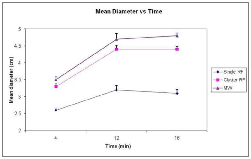
Graph demonstrates change in mean ablation diameter over time by ablation device in ex vivo bovine liver. Note that MW ablations (triangle markers) are larger than single RF (diamond markers) at each time point. There was no statistical difference between MW and cluster RF (square markers). Error bars represent standard error of the mean.
Figure 2.

Gross sections of ex vivo ablation zones. Sections perpendicular to the applicator obtained using a single RF probe (a, 3.0 × 4.0 cm), a cluster RF probe (b, 3.8 × 4.8 cm), and a MW antenna (c, 4.3 × 4.5 cm) for 12 minutes. Note the denser inner char seen in the MW ablation zone (arrow, c).
In vivo results
In the in vivo porcine normal liver model, single MW ablations were significantly larger than single RF ablations at all time points (Table 2, Fig 3, p<0.001 for all time points,4). This held true for mean, minimum and maximum diameters (Table 3). Microwave ablation zones were longer than RF, measuring 5.3±0.2 cm at 5 minutes and 5.8±0.3 cm at 10 minutes (RF: 4.2 ±0.2 and 4.0 ±0.7 cm respectively). However, since the microwave ablations were larger in diameter, the ratio of diameter-to-length was greater for microwave ablations at both time points (MW: 0.66 and 0.70; RF: 0.48 and 0.53). The ablation zone with MW was well seen on ultrasound images, with hyperechoic gas bubbles generated during power delivery that were similar in appearance to RF ablation. The gas was noted to clear rapidly (1–2 minutes), leaving a hypoechoic ablation zone with a slightly hyperechoic halo.
Table 2.
Mean ablation zone diameter in in vivo porcine liver using two different ablation devices.
| Single RF (cm) | Single MW (cm) | p value | |
|---|---|---|---|
| 2 minutes | 1.5 ± 0.1 | 2.6 ± 0.7 | 0.001 |
| 5 minutes | 2.0 ± 0.4 | 3.7 ± 0.8 | 3.0e-06 |
| 7 minutes | 1.8 ± 0.2 | 3.7 ± 0.7 | 0.0003 |
| 10 minutes | 2.1 ±0.3 | 3.8±0.7 | 0.0003 |
Figure 3.
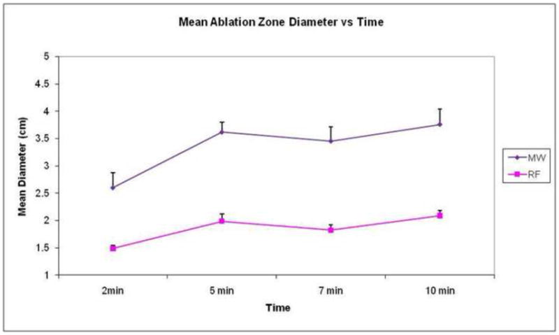
Graph demonstrates mean diameter of ablation zone over time by device in in vivo porcine liver. As seen with the ex vivo data, MW ablations (diamond markers) were significantly larger than RF ablations (square markers) at all time points. Error bars represent standard error of the mean.
Table 3.
Minimum/Maximum diameter, circularity in in vivo porcine liver using two different ablation devices.
| RF min diam (cm) | MW min diam (cm) | RF max diam (cm) | MW max diam (cm) | RF circ | MW circ | |
|---|---|---|---|---|---|---|
| 2 minutes | 1.4±0.17 | 2.0±0.23 | 1.6±0.13 | 3.2±1.2 | 0.94±0.14 | 0.86±0.08 |
| 5 minutes | 1.8±0.35 | 2.6±0.66 | 2.2±0.40 | 4.9±1.3 | 0.90±0.02 | 0.74±0.15 |
| 7 minutes | 1.65±0.26 | 2.1±0.26 | 2.0±0.26 | 5.4±1.1 | 0.92±0.03 | 0.65±0.09 |
| 10 minutes | 1.8±0.28 | 3.4±0.60 | 2.4±0.39 | 4.1±0.9 | 0.90±0.05 | 0.84±0.19 |
MW ablation zones demonstrated significant growth from 2 minutes to 5 minutes (p=0.003), and when comparing 2 minute ablations to time points beyond 5 minutes (p=0.011 2 min vs 7 min; p=0.038 2 min vs 10 min). However, there was no significant difference in ablation zone size when comparing 5 minutes vs 7 minutes (p= 0.76) or 5 minutes vs 10 minutes (p=0.92). A similar trend was seen with the RF ablation zones (2 min vs 5 min p=0.004, 5 min vs 7 min p=0.75, 5 min vs 10 min p=0.43).
Discussion
These results demonstrate that gas-cooled small-diameter microwave antennas consistently create large ablation zones in relatively short time periods. Ablations were significantly larger at all time points when compared to water-cooled RF ablation with a single electrode. The size of the RF ablation zones seen in this study are similar to or larger than those seen in other published in vivo series using similar models. For example, Laeseke et al, obtained a mean diameter of 1.6 cm at 12 minutes using a single water-cooled RF probe (29). The size of the microwave ablation zones reported in this study (3.7 cm at 5 minutes, 3.8 cm at 10 minutes) are much larger than other in vivo experiments (Table 4). Hope et al generated ablation zones using a water cooled 14-gauge antenna in a similar in vivo porcine model with a 915 MHz generator at 45 W with mean diameter of 2.0±2.4 cm at 10 minutes (30). Wright et al obtained a mean diameter of 2.1 cm using a 13-gauge water-cooled device using 40 W at 915 MHz (31). In a separate study, Brace et al used an uncooled 17-gauge antenna to generate ablation zones of 2.9 cm at 12 minutes using 68 W at 2.45 GHz (14). The large thermal lesions reported in our study are likely a result of the high powers possible with this particular gas-cooled system.
Table 4.
Summary table of selected prior MW and RF in vivo results
| Study | Year | Model | System | Ablation zone size |
|---|---|---|---|---|
| Laeseke et al(35) | 2006 | In vivo porcine | Water cooled RF, 17g, 200 W, impedance based pulsing | Mean diam 12 minutes 1.6 cm |
| Wright et al(37) | 2005 | In vivo porcine | 915 MHz, 40 W, 13 g, 10 min, H2O cooling | Mean diam 10 min 2.1 cm |
| Brace et al(20) | 2007 | In vivo porcine | 2.45 GHz, 68 W, 17 g, 12 min, H2O cooling | Mean diam 2 min-2.3 cm 6 min -2.6 cm 12 min 2.9 cm |
| Awad et al(27) | 2007 | In vivo porcine | 2.45 GHz, 100W, 5.7 mm, 2–8 min | Mean vol 2 min-33.5 cm3 4 min-37.5 cm3 8 min-92 cm3 |
| Hines- Peralta et al(21) | 2006 | Ex vivo bovine, in vivo porcine | 2.45GHz, 50–150W, 5.7 mm, 2–20 min | Ex vivo SAD 4.9 cm In vivo SAD 5.7 cm |
| Ianitti et al(13) | 2007 | Clinical | 915 MHz, 45 W, 14g, 10 min | Mean vol 10 cm3 |
| Hope et al(36) | 2008 | In vivo porcine | 915 MHz, 45 W, 14 g, 10 min | Mean diam 2.0±2.4cm |
The significant increase in size in MW ablation zones between 2 minutes and longer time points may be due to the rapid generation of very high temperatures and the decreased impact of charring and desiccation on microwave heating when compared with RF. However, growth of the mean diameter of the ablation zone slows after 5 minutes in this data set. Beyond this time point, the ablation zones become slightly more circular (circularity at 5 minutes 0.73, circularity at 10 minutes 0.84), but there is not much gain in mean diameter with a single probe. A confounding factor is tissue contraction at high temperatures, which is greater for MW than RF due to higher tissue temperatures, and which appears to increase as ablation time progresses(32). Contraction due to water vaporization and tissue desiccation causes the excised specimen to appear smaller than the original (ie, pre-ablation) tissue dimensions. Therefore, while thermal energy may continue to progress radially outward at later time points, such gains may be offset by tissue contraction.
As seen when comparing the ex vivo and in vivo MW data (figure 5), the ablation zone sizes are similar in the first few minutes, but as time progresses the in vivo ablation zones do not continue to grow as much as the ex vivo ablation zones. This effect is not seen with RF (figure 6), where all ex vivo ablation zones are larger than in vivo ablation zones. This trend was also observed in a previous MW ablation study (15). A possible explanation might be that direct microwave heating dominates any positive heat flux from thermal diffusion or negative heat flux caused by blood perfusion during the first few minutes. At later time points, an equilibrium is set up at the front between positive heat flux from thermal diffusion and negative heat flux from blood perfusion; that is, ablation zone expansion is effectively counteracted by blood perfusion at the ablation zone boundary (33, 34). This may also help explain the lack of ablation zone growth after 5 minutes in vivo. In addition, the porcine hepatic lobes are somewhat thinner than those seen in humans, so some the MW ablations were constrained by the tissue surface, especially at longer time points.
Figure 5.
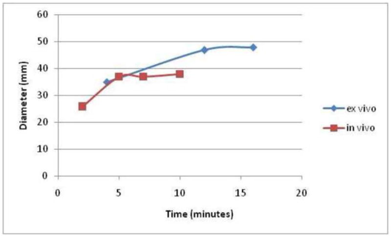
Graph comparing the ex vivo (bovine) and in vivo (porcine) mean MW ablation zone diameter over time. At early time points, the ablation zone sizes are similar between the models, with the in vivo ablation zones smaller at later time points, possibly related in part to tissue contraction and on greater reliance on thermal conduction later in the ablation.
Figure 6.
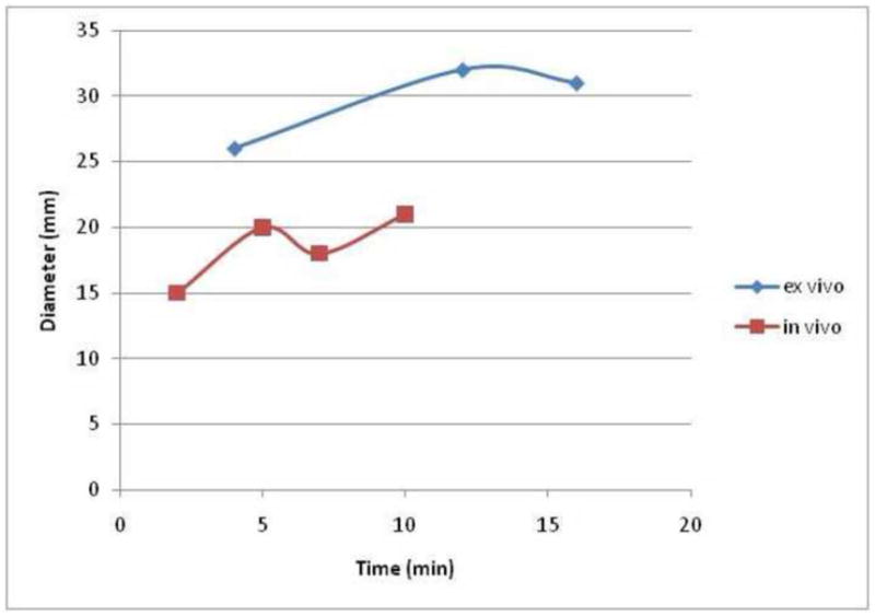
Graph comparing the ex vivo (bovine) and in vivo (porcine) mean RF ablation zone diameter over time. Note that all ex vivo ablation zones are larger than the in vivo ablation zones, in contradistinction to the data seen for MW in figure 7.
While microwave ablations were longer than RF ablations, we noted that the microwave ablations were actually more spherical overall. The greater length was related to the greater overall size of the ablation. However, when working adjacent to vulnerable structures, at the surface of an organ, or treating patients with small tumors, this added length may be problematic. A more precise applicator or technique may be needed to generate a shorter ablation zone for some indications, or adjunctive techniques such as hydrodissection may need to be aggressively utilized. In addition, given that large ablation zones can be achieved over short periods of time with this device, further characterization will likely be required at various power and time settings to provide users with an appropriate range of target ablation sizes.
Limitations of this study include the exclusive use of normal porcine liver rather than a tumor model or cirrhotic liver. Recent data using a water-cooled 2.45 GHz system at 100 W (Amica, HS Medical, Boca Raton, FL) suggest that the expected performance in human tumors can be expected to lie somewhere between the performance seen in ex vivo and in vivo normal porcine livers (35). An additional limitation was that the in vivo portion of this study was performed using an open approach to minimize variations in applicator positioning and maximize the number of ablations per animal and reduce the total number of animals sacrificed for the study. Because this small-caliber gas cooled antenna was specifically designed for percutaneous use, further study in percutaneous and clinical models seems warranted. Some additional characterization of time/power curves for single applicators as well as multi-antenna assessment is also likely needed to guide clinical application.
In conclusion, the gas-cooled microwave ablation system evaluated in this study is able to generate large ablation zones in short times with a small gauge, minimally invasive applicator. Further evaluation of this system in a clinical setting appears warranted. Further study with multi-probe ablation is needed, and further development of a more precise probe with a shorter ablation zone may be helpful for treating smaller tumors.
Figure 4.
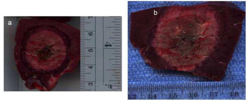
Two gross sections obtained perpendicular to the applicators from in vivo porcine liver. A representative ablation zone created using RF for 10 minutes (a), measuring 2.4 × 2.5 cm, is smaller than that seen with MW (b), measuring 3.3 × 3.8 cm. Note that the MW ablation zone rose to the liver surface, which may constrain ablation zone size.
Acknowledgments
Grant support: 1 R01 CA142737-01, L30 CA136262-01
Footnotes
Disclosures:
Meghan G. Lubner: No disclosures
J. Louis Hinshaw: Stockholder NeuWave Medical, Madison, WI
Anita Andreano: No disclosures
Lisa Sampson: Consultant, NeuWave Medical, Madison, WI
Fred T. Lee, Jr: Stockholder, Board of Directors, NeuWave Medical, Madison, WI
Christopher Brace: Stockholder, consultant NeuWave Medical, Madison, WI.
Preliminary data presented at WCIO June 2010
Publisher's Disclaimer: This is a PDF file of an unedited manuscript that has been accepted for publication. As a service to our customers we are providing this early version of the manuscript. The manuscript will undergo copyediting, typesetting, and review of the resulting proof before it is published in its final citable form. Please note that during the production process errors may be discovered which could affect the content, and all legal disclaimers that apply to the journal pertain.
References
- 1.Kim YS, Rhim H, Cho OK, Koh BH, Kim Y. Intrahepatic recurrence after percutaneous radiofrequency ablation of hepatocellular carcinoma: analysis of the pattern and risk factors. Eur J Radiol. 2006;59:432–41. doi: 10.1016/j.ejrad.2006.03.007. Epub 2006/05/13. [DOI] [PubMed] [Google Scholar]
- 2.Livraghi T, Goldberg SN, Lazzaroni S, Meloni F, Ierace T, Solbiati L, et al. Hepatocellular carcinoma: radio-frequency ablation of medium and large lesions. Radiology. 2000;214:761–8. doi: 10.1148/radiology.214.3.r00mr02761. Epub 2000/03/14. [DOI] [PubMed] [Google Scholar]
- 3.Lu DS, Raman SS, Limanond P, Aziz D, Economou J, Busuttil R, et al. Influence of large peritumoral vessels on outcome of radiofrequency ablation of liver tumors. J Vasc Interv Radiol. 2003;14:1267–74. doi: 10.1097/01.rvi.0000092666.72261.6b. Epub 2003/10/11. [DOI] [PubMed] [Google Scholar]
- 4.Lubner MG, Brace CL, Hinshaw JL, Lee FT., Jr Microwave tumor ablation: mechanism of action, clinical results, and devices. J Vasc Interv Radiol. 2010;21:S192–203. doi: 10.1016/j.jvir.2010.04.007. Epub 2010/08/07. [DOI] [PMC free article] [PubMed] [Google Scholar]
- 5.Dong B, Liang P, Yu X, Su L, Yu D, Cheng Z, et al. Percutaneous sonographically guided microwave coagulation therapy for hepatocellular carcinoma: results in 234 patients. AJR Am J Roentgenol. 2003;180:1547–55. doi: 10.2214/ajr.180.6.1801547. Epub 2003/05/23. [DOI] [PubMed] [Google Scholar]
- 6.Castle SM, Salas N, Leveillee RJ. Initial Experience Using Microwave Ablation Therapy for Renal Tumor Treatment: 18-Month Follow-up. Urology. 2011 doi: 10.1016/j.urology.2010.12.028. Epub 2011/02/18. [DOI] [PubMed] [Google Scholar]
- 7.Iannitti DA, Martin RC, Simon CJ, Hope WW, Newcomb WL, McMasters KM, et al. Hepatic tumor ablation with clustered microwave antennae: the US Phase II Trial. HPB (Oxford) 2007;9:120–4. doi: 10.1080/13651820701222677. Epub 2008/03/12. [DOI] [PMC free article] [PubMed] [Google Scholar]
- 8.Kuang M, Lu MD, Xie XY, Xu HX, Mo LQ, Liu GJ, et al. Liver cancer: increased microwave delivery to ablation zone with cooled-shaft antenna--experimental and clinical studies. Radiology. 2007;242:914–24. doi: 10.1148/radiol.2423052028. Epub 2007/01/19. [DOI] [PubMed] [Google Scholar]
- 9.Liang P, Wang Y. Microwave ablation of hepatocellular carcinoma. Oncology. 2007;72 :124–31. doi: 10.1159/000111718. Epub 2007/12/22. [DOI] [PubMed] [Google Scholar]
- 10.Brace CL. Microwave ablation technology: what every user should know. Curr Probl Diagn Radiol. 2009;38:61–7. doi: 10.1067/j.cpradiol.2007.08.011. Epub 2009/01/31. [DOI] [PMC free article] [PubMed] [Google Scholar]
- 11.Duck F. Physical Properties of Tissue: A Comprehensive Reference Book. London: Academic Press; 1990. [Google Scholar]
- 12.Brace CL. Radiofrequency and microwave ablation of the liver, lung, kidney, and bone: what are the differences? Curr Probl Diagn Radiol. 2009;38:135–43. doi: 10.1067/j.cpradiol.2007.10.001. Epub 2009/03/21. [DOI] [PMC free article] [PubMed] [Google Scholar]
- 13.Simon CJ, Dupuy DE, Mayo-Smith WW. Microwave ablation: principles and applications. Radiographics. 2005;25 :S69–83. doi: 10.1148/rg.25si055501. Epub 2005/10/18. [DOI] [PubMed] [Google Scholar]
- 14.Brace CL, Laeseke PF, Sampson LA, Frey TM, van der Weide DW, Lee FT., Jr Microwave ablation with a single small-gauge triaxial antenna: in vivo porcine liver model. Radiology. 2007;242:435–40. doi: 10.1148/radiol.2422051411. Epub 2007/01/27. [DOI] [PMC free article] [PubMed] [Google Scholar]
- 15.Hines-Peralta AU, Pirani N, Clegg P, Cronin N, Ryan TP, Liu Z, et al. Microwave ablation: results with a 2.45-GHz applicator in ex vivo bovine and in vivo porcine liver. Radiology. 2006;239:94–102. doi: 10.1148/radiol.2383050262. Epub 2006/02/18. [DOI] [PubMed] [Google Scholar]
- 16.Shock SA, Meredith K, Warner TF, Sampson LA, Wright AS, Winter TC, 3rd, et al. Microwave ablation with loop antenna: in vivo porcine liver model. Radiology. 2004;231:143–9. doi: 10.1148/radiol.2311021342. Epub 2004/04/01. [DOI] [PubMed] [Google Scholar]
- 17.Lu MD, Xu HX, Xie XY, Yin XY, Chen JW, Kuang M, et al. Percutaneous microwave and radiofrequency ablation for hepatocellular carcinoma: a retrospective comparative study. J Gastroenterol. 2005;40:1054–60. doi: 10.1007/s00535-005-1671-3. Epub 2005/12/03. [DOI] [PubMed] [Google Scholar]
- 18.Yang D, Converse MC, Mahvi DM, Webster JG. Measurement and analysis of tissue temperature during microwave liver ablation. IEEE Trans Biomed Eng. 2007;54:150–5. doi: 10.1109/TBME.2006.884647. Epub 2007/01/31. [DOI] [PubMed] [Google Scholar]
- 19.Bhardwaj N, Strickland AD, Ahmad F, Atanesyan L, West K, Lloyd DM. A comparative histological evaluation of the ablations produced by microwave, cryotherapy and radiofrequency in the liver. Pathology (Phila) 2009;41:168–72. doi: 10.1080/00313020802579292. Epub 2009/01/20. [DOI] [PubMed] [Google Scholar]
- 20.Yu NC, Raman SS, Kim YJ, Lassman C, Chang X, Lu DS. Microwave liver ablation: influence of hepatic vein size on heat-sink effect in a porcine model. J Vasc Interv Radiol. 2008;19:1087–92. doi: 10.1016/j.jvir.2008.03.023. Epub 2008/07/01. [DOI] [PubMed] [Google Scholar]
- 21.Awad MM, Devgan L, Kamel IR, Torbensen M, Choti MA. Microwave ablation in a hepatic porcine model: correlation of CT and histopathologic findings. HPB (Oxford) 2007;9:357–62. doi: 10.1080/13651820701646222. Epub 2008/03/18. [DOI] [PMC free article] [PubMed] [Google Scholar]
- 22.Liang P, Wang Y, Yu X, Dong B. Malignant liver tumors: treatment with percutaneous microwave ablation--complications among cohort of 1136 patients. Radiology. 2009;251:933–40. doi: 10.1148/radiol.2513081740. Epub 2009/03/24. [DOI] [PubMed] [Google Scholar]
- 23.Wolf FJ, Grand DJ, Machan JT, Dipetrillo TA, Mayo-Smith WW, Dupuy DE. Microwave ablation of lung malignancies: effectiveness, CT findings, and safety in 50 patients. Radiology. 2008;247:871–9. doi: 10.1148/radiol.2473070996. Epub 2008/03/29. [DOI] [PubMed] [Google Scholar]
- 24.Strickland AD, Clegg PJ, Cronin NJ, Swift B, Festing M, West KP, et al. Experimental study of large-volume microwave ablation in the liver. Br J Surg. 2002;89:1003–7. doi: 10.1046/j.1365-2168.2002.02155.x. Epub 2002/08/03. [DOI] [PubMed] [Google Scholar]
- 25.Brace CL, Laeseke PF, van der Weide DW, Lee FT. Microwave Ablation With a Triaxial Antenna: Results in ex vivo Bovine Liver. IEEE Trans Microw Theory Tech. 2005;53:215–20. doi: 10.1109/TMTT.2004.839308. Epub 2007/12/15. [DOI] [PMC free article] [PubMed] [Google Scholar]
- 26.Shibata T, Iimuro Y, Yamamoto Y, Maetani Y, Ametani F, Itoh K, et al. Small hepatocellular carcinoma: comparison of radio-frequency ablation and percutaneous microwave coagulation therapy. Radiology. 2002;223:331–7. doi: 10.1148/radiol.2232010775. Epub 2002/05/09. [DOI] [PubMed] [Google Scholar]
- 27.Wang Y, Sun Y, Feng L, Gao Y, Ni X, Liang P. Internally cooled antenna for microwave ablation: results in ex vivo and in vivo porcine livers. Eur J Radiol. 2008;67:357–61. doi: 10.1016/j.ejrad.2007.07.015. Epub 2007/09/05. [DOI] [PubMed] [Google Scholar]
- 28.RDCT. R: A language and environment for statistical computing. R Foundation for Statistical Computing; Vienna, Austria: 2009. p. http://www.R-project.org. [Google Scholar]
- 29.Laeseke PF, Sampson LA, Haemmerich D, Brace CL, Fine JP, Frey TM, et al. Multiple-electrode radiofrequency ablation creates confluent areas of necrosis: in vivo porcine liver results. Radiology. 2006;241:116–24. doi: 10.1148/radiol.2411051271. Epub 2006/08/25. [DOI] [PMC free article] [PubMed] [Google Scholar]
- 30.Hope WW, Schmelzer TM, Newcomb WL, Heath JJ, Lincourt AE, Norton HJ, et al. Guidelines for power and time variables for microwave ablation in a porcine liver. J Gastrointest Surg. 2008;12:463–7. doi: 10.1007/s11605-007-0248-2. Epub 2007/09/07. [DOI] [PubMed] [Google Scholar]
- 31.Wright AS, Sampson LA, Warner TF, Mahvi DM, Lee FT., Jr Radiofrequency versus microwave ablation in a hepatic porcine model. Radiology. 2005;236:132–9. doi: 10.1148/radiol.2361031249. Epub 2005/07/01. [DOI] [PubMed] [Google Scholar]
- 32.Brace CL, Diaz TA, Hinshaw JL, Lee FT., Jr Tissue contraction caused by radiofrequency and microwave ablation: a laboratory study in liver and lung. J Vasc Interv Radiol. 2010;21:1280–6. doi: 10.1016/j.jvir.2010.02.038. Epub 2010/06/12. [DOI] [PMC free article] [PubMed] [Google Scholar]
- 33.Schramm W, Yang D, Haemmerich D. Contribution of direct heating, thermal conduction and perfusion during radiofrequency and microwave ablation. Conf Proc IEEE Eng Med Biol Soc. 2006;1:5013–6. doi: 10.1109/IEMBS.2006.259288. Epub 2007/10/20. [DOI] [PubMed] [Google Scholar]
- 34.Schramm W, Yang D, Wood BJ, Rattay F, Haemmerich D. Contribution of direct heating, thermal conduction and perfusion during radiofrequency and microwave ablation. Open Biomed Eng J. 2007;1:47–52. doi: 10.2174/1874120700701010047. Epub 2007/01/01. [DOI] [PMC free article] [PubMed] [Google Scholar]
- 35.Goldberg SN, Meloni F, Tosoratti N, Nissenbaum I, Appelbaum L, Solbiati L. Parameter characterization for Microwave Tumor Ablation: Comparison of Experimental and HCC data. World Conference on Interventional Oncology; 2011. [Abstract]. In press. [Google Scholar]


