Abstract
The importance of mesenchymal stem cell (MSC) in vascular regeneration is becoming increasingly recognized. However, few in vitro studies have been performed to identify the effects of environmental elasticity on the differentiation of MSC into vascular cell types. We utilized electrospinning and photopolymerization techniques to fabricate a 3D PEGdma nanofiber hydrogel matrix with a tunable elasticity for use as a cellular substrate. Compression testing demonstrated that the elastic modulus of the hydrated 3D matrices ranged from 2 to 15 kPa, similar to the in-vivo elasticity of the intima basement membrane and media layer. MSC seeded on rigid matrices (8–15 kPa) showed an increase in cell area compared to those seeded on soft matrices (2–5 kPa). Furthermore, the matrix elasticity guided the cells to express different vascular-specific phenotypes with high differentiation efficiency. Around 95% of MSC seeded on the 3D matrices with an elasticity of 5 kPa showed Flk-1 endothelial markers within 24 hr, while only 20% of MSC seeded on the matrices with elasticity greater than 8 kPa demonstrated Flk-1 marker. In contrast, around 80% of MSC seeded on 3D matrices with elasticity greater than 8 kPa demonstrated smooth muscle α-actin marker within 24 hr, while less than 10% of MSC seeded on 3D matrices with elasticity less than 5 kPa showed α-actin markers. The ability to control MSC differentiation into either endothelial or smooth muscle-like cells based purely on the local elasticity of the substrate could be a powerful tool for vascular tissue regeneration.
Keywords: Elasticity, 3D matrix, mesenchymal stem cell, vascular differentiation, nanofiber
1. Introduction
Vascular diseases affect 1 in 3 Americans [1]. In 40 % of the cases, the treatment requires surgical replacement of a diseased or dysfunctional blood vessel with a vascular graft. Synthetic vascular grafts always cannot match the efficacy of healthy vessels, leading to short-term or long-term graft failures such as thrombosis or stenosis. These failures may be partly prevented by the development of a robust endothelial layer utilizing the patient’s cells along the inner wall of the graft. Recent developments in vascular tissue engineering have shown exciting potentials for using both endothelial cells (EC) and smooth muscle cells (SMC) on a degradable scaffold to regenerate blood vessels [1, 2]. However, obtaining a sufficient number of vascular cells is difficult; as it requires invasive surgery on the patient or donor and these cells have a limited expansion capability in vitro [1]. MSC is an alternative cell source recently employed in vascular graft or tissue engineering [3, 4]. MSCs are multipotent and thromboresistant, can be easily obtained through a bone marrow biopsy from a patient or a compatible donor, have a large expansion capability given proper environments in vitro, and thus are increasingly explored for regenerative medicine [5]. Studies in the last decade have demonstrated that MSC differentiation and spreading can be controlled by the local mechanical elasticity using a polyacrylamide gel with varied modulus as a two-dimensional (2D) cell substrate [6]. It has been demonstrated that the gels that replicated the modulus of neural, muscle and bone tissue directed the differentiation of MSCs towards neural, myogenic, and osteogenic cells, respectively [7]. Utilizing the local substrate elasticity to control MSC differentiation and activity is an elegant approach to achieve spatial control of cell behaviors.
In contrast to the 2D cell culture employed by most of these studies, the in-vivo extracellular matrix provides a cellular microenvironment characterized by a three-dimensional (3D) nanofiber network with pores that allow for cellular migration and the influx of fluid and nutrients. Studies have shown that cellular responses such as morphology, adhesion and differentiation are greatly different between cells seeded on a flat, 2D substrate and those in a 3D porous matrix [8]. Electrospinning is a fabrication process that utilizes a high voltage source to stretch a polymer solution into nanofibers, producing 3D nanofiber matrices. This process allows control over fiber diameter and porosity, producing an ideal 3D substrate for cell scaffolding [9]. Recently, Tan et al.[10] electrospun a photopolymerizable polymer solution of polyβ-amino ester and poly(ethylene oxide) (PEO) into a 3D matrix. Their study resulted in a scaffold with a young’s modulus of in the range of 5 MPa, good for tendon and ligament tissue engineering [10]. However, for soft tissues like blood vessels, nanofibers with extremely low elasticity (around 2–15 kPa) will be needed [11, 12]. In addition, the artery has a multilayer structure and the elasticity of the layers varies; the basement membrane around the endothelium in the intima layer is the softest, the connective tissue in the adventitia layer is the most rigid, and the modulus of smooth muscle in the medial layer is in between. EC reside on top of the soft basement membrane while SMC live in the stiffer medial layer [13, 14]. The hypothesis underlying this present study is that replicating the elasticity of the mechanical microenvironments found in the vessel basement membrane and medial layers will induce MSC to differentiate towards vascular cells with EC or SMC-like characteristics, respectively.
To test the hypothesis, we have developed 3D photopolymerizable nanofiber grafts (NFG) with low elastic modulus (in the range of 2 to 15 KPa) by electrospinning. The elasticity of these grafts can be dynamically controlled by adjusting the photopolymerization time. These grafts were used to study the effects of modulus on MSC spreading, penetration and differentiation into EC and SMC.
2. Methods
2.1 Nanofiber Scaffold Fabrication
Polyethylene glycol dimethacrylate (PEGdma) with a molecular weight of 3000 was synthesized utilizing the method developed by Lin Gibson et al [15]. Approximately 90% of the end groups were modified with methacrylates as determined by 1H NMR analysis. An electrospinning solution composed of 3.2% wt PEGdma 3000, 3.4% wt PEO (MW 40,000, Sigma-Aldrich, St Louis, MO), 0.4 % wt of Irgacure 2959 (I2959, 0.6 mg/ml in DI H20, Ciba, Tarrytown, NY) and 93% DI H2O was mixed for one hr with magnetic stir bar. PEGdma 3000 photopolymerizable nanofiber grafts (NFGs) were fabricated by electrospinning on a custom set up composed of a high voltage power supply (Gamma High Voltage Research, Ormond Beach, FL), grounded collecting surface, motorized syringe pump, and a 14 mm syringe. The solution (2 ml) was spun at a distance of 26 cm from the stationary collecting surface, a voltage of 22 kV, and a flow rate of 1.10 ml/hr. NFGs with a thickness of around 0.3 mm were cut into 7/8-inch diameter disks and placed in glass vials. Vials were then vacuum-sealed and NFGs were photopolymerized under 365 nm light with an average intensity of 15 mW/cm2.
2.2 FTIR Analysis
NFG double bond conversion was evaluated with mid-range fourier transform infrared spectroscopy (FTIR) (Nicolet 4700, Thermo Fisher Scientific, Waltham, MA) by examining the disappearance of the C=C peak within the acrylate group (~1635 cm−1) on a dry NFG. Three NFGs were photopolymerized for 2, 5 and 30 min respectively, and FTIR was then performed on each sample. To account for sample and background variation, data were normalized with the C=O peak located in the range from 1650 to 1726 cm−1, which is independent of photopolymerization. Data were analyzed using Opus software (Brucker Optics, Billerica MA).
2.2 Scanning Electron Microscopy Imaging
Scanning electron microscopy (FESEM, JSM-7401F, Jeol Ltd, Tokyo, Japan) was used to examine the fibrous structure of the NFG samples in dry and hydrated states. For hydrated samples, NFGs were photopolymerized for 5 and 30 min, and submerged in DI H2O for 24 hr. Then, they were submerged in liquid nitrogen (−195 °C), dried in a critical-point drying chamber for approximately 48 hr, and then imaged with FESEM. The fiber structure was imaged at 400 and 2000 magnifications. Image J was used to analyze changes in fiber diameter and porosity.
2.3 Equilibrium Swelling Ratio
The equilibrium swelling ratio, q, for each photopolymerization time have been calculated as
The ‘dry mass’ is the mass of the nanofiber graft after photopolymerization, in a dry state. The sample was then exposed to DI H2O for 48 hr, and finally weighed to determine the ‘equilibrium swelling mass’.
2.4 Differential Interference Contrast (DIC) Microscopy Imaging
To examine the changes of fiber structure in the hydrated NFGs and study the effects of crosslinking on the structure, the NFGs were submerged in DI H2O for 5 min after exposure to UV light. Images were then taken at 20x magnification on a DIC optical microscope (Axioskop 40, Carl Ziess, Oberkochen, Germany).
2.5 Tensile Testing
Tensile testing was performed using an MTS Insight electromechanical testing system (MTS Systems Corp., Eden Prairie, MN, USA). Five PEGdma NFGs that had not been photopolymerized were tested in the dry state. Ten PEGdma NFGs that had been photopolymerized for 30 min were prepared; five of the scaffolds were tested in the dry state. The remaining five were submerged in DI H2O for 24 hr and tested in an environmental chamber submerged in PBS. Four NFGs that had been photopolymerized for 2 minutes and four NFGs that had been photopolymerized for 5 minutes were also submerged in DI H2O for 24 hr and tested in an environmental chamber submerged in PBS. All scaffolds were cut to 5mm wide by 25 mm length. Sandpaper was attached to the tensile test grips to prevent slipping. A strain rate of 0.03 mm/mm/s was used, following the method used in a previous research [10]. Uniaxial tensile testing was performed on all samples till failure. Samples with data indicating slippage or excessive noise were not used. The NFGs tested in the dry state showed a linear behavior, and a linear fit of the stress strain curve was used to determine the modulus. The NFGs tested in the hydrated state demonstrated a classic heel toe stress-strain curve. The elastic modulus of hydrated NFGs was determined from the low strain region (10 to 30%) of the curve.
2.6 Rheometer Testing
Changes in storage modulus (G′) of NFGs due to increased photopolymerization time were characterized using a rheometer (γ = 2%, ω = 1 rad/s for linear viscoelastic regime, ARES TA rheometer, TA Instruments, New Castle, DE). NFG samples that were 0.3 mm thick with 7/8 inch in diameter were photopolymerized for 2, 5, 15, 30 or 60 min, and then submerged in DI H2O for 24 hr. NFGs were tested with a parallel plate configuration and a temperature-controlled Peltier flat plate at 37 °C. Adhesive sand paper was attached to the bottom and top plates to prevent slippage between NFGs and plates. A vertical load of 16 grams was also applied to all samples to prevent slippage. A strain sweep at a frequency of 1 rad/s and a frequency sweep at a strain of 2 % were run on each sample. Data were inspected for slippage or tearing, and only data from the linear visco-elastic region (LVE) in the strain sweep were used to determine the G′. The LVE region was defined as the storage modulus (G′) having a change of less than 60 Pa between 1 and 10 % strain, suggesting strain independent behavior.
2.7 Compression Testing
The compression modulus of NFGs photopolymerized for 2, 5, 15, 30 and 60 min was characterized using a MTS Synergie 100 (MTS, Eden Prairie, MN) with a parallel plate set up. All tests were completed in a hydrated condition, on a 10 N load cell at a strain rate of 0.50 mm/min up to a maximum strain of 15%. A total of 4 samples per photopolymerization time were tested, and elastic modulus was calculated from the linear elastic region between 10 to 15%.
2.8 Cell Culture
NFGs were photopolymerized, submerged in DI H2O for 24 hr and sterilized with 70% ethanol. Prior to cell seeding, the NFGs were coated with 0.3 % type I rat tail collagen (BD Biosiences, Bedford, MA). Rat MSCs from (Lonza Group Ltd, Switzerland) with passages 2–5 were cultured in Dulbeccos Modified Eagles Media (DMEM, Sigma-Aldrich, St Louis, MO), with 10% defined FBS for MSCs and 1% Penn/Strep (Invitrogen, Carlsbad, CA). To seed cells on the top of NFGs, 300 μl of 150,000 cells/ml media were used for each sample. Cells were seeded in a circular 1.57 mm2 area defined by a rubber gasket (Grace Biolabs, Bend, OR) on top of the sample. For comparison, primary vascular ECs and SMCs freshly separated from pulmonary blood vessels were cultured DMEM with 10% FBS and 1% Penn/Strep. SMCs were cultured in a collagen gel and ECs were cultured on it.
2.9 Measurements of Cell Spreading Area
After 20-hr culture, cell assay (LIVE/DEAD kit obtained from Invitrogen Corp., Carlsbad, CA) was performed to evaluate MSC spreading on 2 min, 5 min, 15 min, 30 min and 60 min NFGs. To start the assay, 150 μl of the Live/Dead assay solution containing 10 ml PBS, 20 μl of 2mM EthD-1 and 5 μl of 4mM calcein AM was added on each NFG. NFGs were then incubated in the dark for 30 min, after which cells were imaged on an upright fluorescence microscope (Axiovert S100, Carl Ziess, Oberkochen, Germany) with 20x magnification. The applied stain presented by live cells was green (calcein AM) while the nuclei of dead cells were stained red (EthD-1). Image-J software (NIH, Bethesda, MD) was used to measure the cell area and analyze the cell morphology in the obtained images. For each graft, 10 representative cells were measured for spreading area; only cells that were entirely on a single z-plane were imaged to ensure correct area calculations.
2.10 Immunofluorescent Staining
Immunofluorescent staining of cells with FLK1 (endothelial cell markers) and anti-smooth muscle alpha-actin (SMA, a smooth muscle cell marker) was used to characterize vascular differentiations of MSC. Cells were seeded for 24 hr on 2, 5, 15, 30 and 60 min NFGs. Samples were fixed with methanol at −8 °C, blocked with 3% BSA, and incubated with primary rabbit polyclonal anti-SMA (Sigma-Aldrich, St Louis, MO), or primary mouse monoclonal anti-FLK1 (Santa Cruz Biotechnology, Santa Cruz, CA). Following primary antibody coupling, samples were washed in PBS and incubated with secondary anti-mouse IgG antibody conjugated with Alexa 488 and anti-rabbit IgG antibody conjugated with Alexa 594. Finally, the samples were mounted with DAPI SlowFade (Invitrogen, Carlsbad, CA) and imaged. Fluorescently labeled cells were evaluated using an epifluorescence and confocal microscope (Zeiss, Peabody, MA). Images from each fluorescence channel were merged using Picassa software (Google, Mountain View, CA).
2.11 Real Time RT- PCR
Total cellular RNA from each sample was extracted using RNeasy Mini Kit (Qiagen, Hilden, Germany) according to the manufacturer’s instructions. Complementary DNA was synthesized from 1 ng of total cellular RNA using iScript cDNA Synthesis Kit (Bio-Rad, Hercules, CA). Primer sequences for amplification of Flk-1 and SMA are shown in Table 1. The SYBR Green I assay and the iCycler iQ real-time PCR detection system (Bio-Rad MyiQ Real-Time PCR System, Hercules, CA) were used for detecting real-time quantitative PCR products from 2 ng of reverse-transcribed cDNA. PCR thermal profile consisted of 95°C for 10 min followed by 40 cycles of 95°C for 15 s, 60°C for 30 s and 95°C for 1 min. Genes were normalized to the housekeeping gene GADPH, and fold change relative to the control was calculated using the DCT method 36.
Table 1.
Primer sequences of rat genes for real time PCR analysis.
| Genes | Forward Primer (rat) | Reverse Primer (rat) |
|---|---|---|
| GADPH | TTGGAGGCCATGTAGGCCAT | CCTCTGGAAAGCTGTGGCGT |
| Flk-1 | ATGGAAGAGGATTCTGGA | CACGGTGGTGTCTGTGTC |
| SMA | CATCTCCAGAGTCCAGCACA | ACTGGGACGACATGGAAAAG |
2.12 Statistical Analysis
Statistical testing was performed using MVPstats software (MVP Programs, Vancouver, WA) or SPSS software (IBM, Chicago, IL). For comparing two groups with equal variances, a student’s t-test was used. For comparing two groups with unequal variances and unequal sample sizes, Welch’s t-test was used. For multiple group comparisons, a one-way ANOVA test was run on both the groups’ means and variances. If the groups had equivalent variances, a Tukey Post-Hoc analysis was further performed. If the groups had unequivalent variances, a Games-Howell Post Hoc was further performed. When analyzing the rheological data, due to disproportionate sample sizes, an unweighted means analysis was used to compare groups [16].
3. Results
3.1 Synthesis of nanofiber grafts with varying degrees of crosslinking
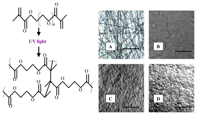
PEGdma 3000 was selected for its high elasticity, cytocompatibility, and ability to be photopolymerized [17, 18, 19]. As it was difficult to form continuous nanofibers when electrospinning a low molecular weight polymer solution like PEGdma 3000, PEO with a molecular weight of 40,000 was added to the electrospinning solution to act as a carrier polymer. As PEO is water soluble, it acts as a sacrificial polymer that can be washed out of the scaffold over the time in water resulting in a NFG composed of PEGdma 3000. We electrospun a solution with a PEG-to-PEO ratio of 1.0-to-1.1. This was the highest weight ratio of PEG to PEO, which resulted in continuous nanofibers; increasing the amount of PEG in solution caused beading and inconsistent nanofibers. The resulting NFGs were composed of 48.35% wt PEGdma 3000, 52.60% wt PEO, and 0.05% wt I2959. Figure 1A shows the PEGdma 3000 NFG with consistent and continuous nanofibers characterized by minimal webbing or beading.
Figure 1.
Poly(etheylene glycol) dimethacrylate undergoing photopolymerization. UV light causes the initiator to dissociate into free radicals that react with the vinyl groups, initiating the chain polymerization reaction and propagation until termination. DIC images show the fiber structure of a dry NFG scaffold (A), a hydrated NFG with 0 min of photopolymerization (no fibers remain) (B), a hydrated NFG with 5 min of photopolymerization (fibers remain) (C), and a hydrated NFG with 30 min of photopolymerization (fibers remain) (D). Images were taken at 40x magnification. Scale bar: 2mm.
The crosslinking of PEGdma 3000 is based on radical chain photopolymerization of its methacrylate groups in the presence of a photoinitiator (I2959) and UV light. PEGdma 3000 NFGs were not sufficiently crosslinked, indicated by dissolution of the fibers in an aqueous environment, when polymerized in the presence of normal atmosphere due to oxygen inhibition. Photopolymerizing NFGs in vacuum resulted in crosslinked scaffolds that maintained a solid, fibrous structure after water submersion. The DIC image of NFGs with no photopolymerization showed loss of fibrous structure after exposure to DI H2O (Figure 1B). The DIC microscopy images of NFGs with photopolymerization times of 5 and 30 min showed that the fibrous structure of both materials remained intact and swollen after hydration in DI H2O (Figures 1C and 1D).
3.2 FTIR analysis indicates degree of conversion increases with photopolymerization time
Mid-range FTIR was used to characterize the degree of conversion by monitoring the disappearance of the reactive acylate peak at 1637 cm−1. Due to the low concentration of acrylates present as a result of the high molecular weight of PEGdma 3000, the NFG showed a small acrylate peak. To account for the sample and background variation, data were normalized with the C=O peak located in the range from 1650 to 1726 cm−1, which is independent of photopolymerization. FTIR was performed on the samples photopolymerized for 0, 2 and 30 min. Table 2 summarizes the results. Results showed that the acylate peak in the NFG samples photopolymerized for 30 min decreased by 30% when compared with those with no exposure to UV. The NFG samples photopolymerized for 2 min showed 10 % decrease in acrylate peak compared to those with no exposure to UV.
Table 2.
Midrange FTIR data from NFGs with various photopolymerization times. Data table shows the calculated peak areas of the C=O and C=C peaks, as well as the ratio of the C=C to C=O peak. The peak area was calculated with Opus software. Data was taken in absorbance mode from 400 cm−1 to 4000 cm−1 wavelengths.
| Photopolymerization Time | Peak Area: 1762- 1675 cm-1 | Peak Area: 1650- 1607 cm-1 | Ratio (%) |
|---|---|---|---|
| 0 min | 0.512 | 0.057 | 11.11 |
| 2 min | 0.559 | 0.056 | 10.02 |
| 30 min | 0.637 | 0.049 | 7.69 |
3.3 NFGs with varying degrees of photopolymerization have similar fibrous structures after hydration
SEM images of NFGs in the dry state showed a consistent fibrous structure with fibers ranging from 0.50 to 1.0 μm, and minimal beading or webbing at fiber joints (Figure 2A). This was consistent to the DIC image results. SEM images were also taken on NFGs which had undergone 24 hr of DI H2O exposure followed by 48 hr of freeze drying. These images showed intact fiber networks in 5- and 30- min NFGs, demonstrating that fiber networks remained intact after 24 hr of H2O submersion. (Figure 2B–C). Some fiber coagulation after swelling in the water was found in both NFG samples. Overall, there were minimal differences in porosity and structure noted between 5-min and 30-min NFGs after 24 hr of DI H2O exposure (Table 3). For analysis, 10 fibers on each of the SEM images for dry NFG, 5 min NFG and 30 min NFG were randomly selected and the fiber diameter was measured using Image J software. Assuming material isotropy, comparisons of the volume of dry NFG fiber versus that of hydrated NFG fiber showed a fiber-swelling ratio of Q = 2.5 after 24 hr of DI H2O exposure. No significant differences in NFG fiber diameter or porosity were found between the hydrated NFGs photopolymerized for 5 min and 30 min (p>0.4). The average volume swelling ratio of these 3D matrices due to hydration was Q = 27, indicating a highly saturated porous structure. Porosity in the matrix gave more area for water to infiltrate, resulting in much higher volume swelling ratio compared to that of a single nanofiber. This was an interesting result as the low nanofiber swelling ratio was closer to the volume swelling ratio of the solid PEGdma gels (Q = 6.9), [19] which did not allow cell movement or penetration over the gel thickness. The high matrix swelling ratio was an indication of the pores between nanofibers that allowed for cellular adhesion and migration into the 3D matrix.
Figure 2.
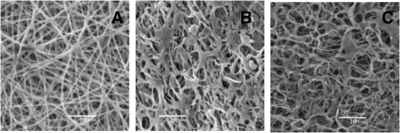
SEM images of dry NFG (A), hydrated NFG photopolymerized for 5 min (B) and hydrated NFG photopolymerized for 30 min (C). All the images show PEGdma/PEO electrospun NFGs. Images were taken at 2000x magnification. Hydrated samples were exposed to DI H2O for 24 hr, and freeze-dried for 48 hr. Scale bar is 10 μm.
Table 3.
Average fiber diameter and average porosity in area fraction for dry NFG, hydrated NFG photopolymerized for 5 min, and hydrated NFG photopolymerized for 30 min.
| Sample | Average Fiber Diameter (μm) (n = 10) | Average Porosity (Area fraction) |
|---|---|---|
| Dry NFG | 0.60 ± 0.14 | 18.4% |
| Hydrated 5-min-UV NFG | 0.80 ± 0.19 | 18.5% |
| Hydrated 30-min-UV NFG | 0.77 ± 0.17 | 21.0% |
Finally, the equilibrium mass swelling ratio of the NFGs was found to vary from 41 (5-min sample) to 22.5 (60-min sample). The equilibrium swelling ratio is a function of crosslinking density; as crosslinking density increases, less water can be absorbed into the gel [20]. Our data reflects this mechanism; samples with short photopolymerization time (2 and 5 min) results in low crosslinking density and therefore a high equilibrium swelling ratio, whereas samples with high photopolymerization time (15, 30 and 60 min) resulted in a higher crosslinking density and therefore a lower equilibrium swelling ratio. No statistical differences in equilibrium swelling ratio were found between 15, 30 and 60 min samples, or between 2 and 5 min samples.
3.4 Mechanical testing shows increase in modulus with increasing photopolymerization time
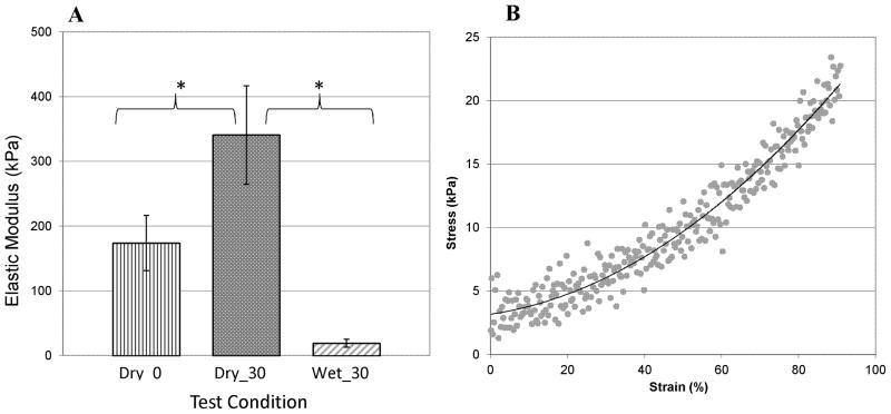
Tensile tests were performed on NFGs photopolymerized for 0 and 30 min in the dry condition, and on NFGs photopolymerized for 30 min (Wet_30) in the hydrated condition. Results showed that dry NFGs photopolymerized for 30 min (Dry_30) had an elastic modulus of about 350 kPa (Figure 3). Statistical analysis using Welches unpaired t-test showed the elastic modulus of Dry_30 samples was significantly higher than that of dry grafts without photopolymerization (Dry_0). The hydrated NFGs (Wet_30) had an elastic modulus of 20±4 kPa in the low strain region from 10 to 30%. This indicates the elastic modulus of 30 min photopolymerized NFGs was reduced by more than 16-fold when exposed to water. Noise levels in testing resulted in variations elastic modulus ranged from ±4 kPa to ± 8 kPa. To compare changes in tensile modulus with photopolymerization time, tensile tests were also performed on NFGs photopolymerized for 2 and 5 min in the hydrated condition. However, due to the high noise levels, no significant variations in elastic modulus were detected with varied polymerization time in wet samples.
Figure 3.
Tensile modulus is determined as a function of the photopolymerization time and testing environment. Dry_0 represents the NFG samples tested in the dry atmosphere with no UV exposure. Dry_30 represents the NFG samples that were photopolymerized for 30 min and tested in the dry atmosphere. Wet_ 30 represents the NFG samples that were photopolymerized for 30 min, submerged in DI H2O for 24 hr and tested in an environmental chamber submerged in PBS. Vertical bars indicate standard deviation. “*” shows statistical differences between the groups, with p<0.05.
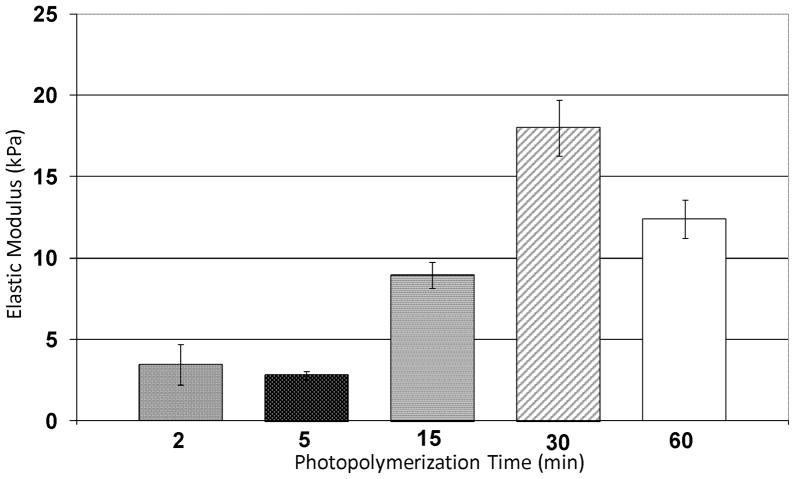
Compression tests were performed on NFGs photopolymerized for 2, 5, 15, 30 and 60 min. All samples were tested in a hydrated state. Data shown in Figure 4 indicated the modulus of NFGs varied from 2 ±1 kPa using short photopolymerization times (2 or 5 min) to 15 ± 2 kPa using longer photopolymerization times (30 or 60 min).
Figure 4.
Compressive testing of hydrated NFGs with 2, 5, 15, 30 and 60 min of photopolymerization time. NFGs show characteristic heal-toe curve: modulus values were taken from 10 to 15% strain region. n = 3 or 4 for each photopolymerization time. Horizontal lines indicate groups that are statistically equivalent, p > 0.01. Vertical lines indicate standard error.
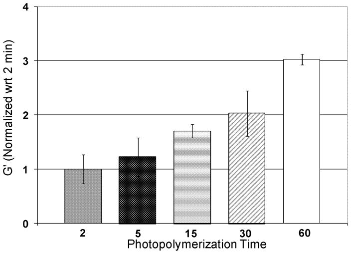
To characterize how the NFG storage modulus varies with the photopolymerization time, a parallel plate rheometer was used. NFG samples photopolymerized for 2, 5, 15, 30 and 60 min were tested in a hydrated state at 37 °C. Data were normalized with respect to the average G′ value of two min samples to show fold differences. Figure 5 demonstrates the storage modulus increases with increasing photopolymerization time. All the NFGs with different photopolymerization times were found to have significantly different storage moduli, indicating that the photopolymerization times of 2, 5, 15, 30, and 60 min produce NFGs with varying stiffness. Storage moduli range from 125 Pa at 2 min to 500 Pa at 60 min.
Figure 5.
Results from rheometer tests for hydrated NFGs photopolymerized for 2, 5, 15, 30 and 60 min. All data have been normalized with respect to 2 min samples. The G values of all photopolymerization times are statistically different, p < 0.05.
3.5 Cell penetration into a 3D NFG not a 2D hydrogel
MSCs were seeded on top of the polymerized NFGs and gels, and fixed after 24 hr of seeding. MSCs were found at numerous depths throughout the nanofibrous graft (Figures 6A, 6B, 6D). In comparison, cells seeded on a solid PEGDA 3000 hydrogels showed no penetration after 24 hr of seeding. (Figure 6C)
Figure 6.
MSCs seeded on NFGs photopolymerized for 5 min (A) and 30 min (B). The images show cells at various graft penetration levels with in-focus cells and out-of-focus cells on one z-plane. Cells were only found on the surface of solid PEGdma 3000 gel photopolymerized for 30 min (C). Scale bar = 30 mm. (D) Confocal image of MSC nuclei (DAPI stain) on NFG photopolymerized for 30 min: x–y, x–z and y–z views of the construct. PEGdma nanofibers result in refraction of light, making it difficult to obtain confocal images in the green and red channels
3.6 MSC spreading on NFGs is correlated to matrix stiffness
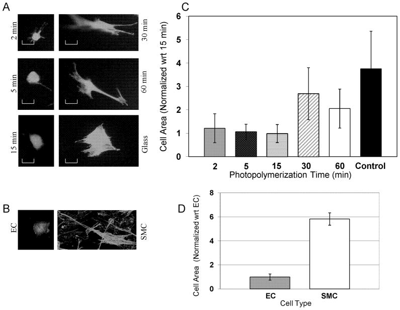
To examine the effects of 3D nanofiber modulus on cell morphology, NFGs were photopolymerized for 2 min, 5 min, 15 min, 30 min and 60 min, respectively. MSCs were seeded on top of each NFG. The cell spreading was analyzed by measuring cell area using Image J software. For each NFG, 10 representative cells were measured and averaged for comparisons. Results in Figure 7 demonstrated that MSCs on 2 min, 5 min, and 15 min NFGs exhibited statistically equivalent average cell areas. Also, cells on these matrices demonstrated a less polarized morphology. MSC areas on 30 min and 60 min NFGs also had statistically equivalent cell areas. Cells on these stiffer matrices demonstrated a striated, elongated morphology. Additionally, MSCs seeded on 30 min and 60 min NFGs were found to have statistically larger areas when compared to MSCs seeded on 5 min and 15 min NFGs. Furthermore, MSCs seeded on the glass were found to be significantly larger than MSCs seeded on any NFG. Cells on the glass demonstrated a multi-polarized morphology. To understand how these differences in MSC spreading area compare to the differences in spreading area of vascular SMC and EC, the areas of EC and SMC were measured. SMC were found to have a significantly larger area than ECs.
Figure 7.
MSC spreading increases with nanofiber graft modulus. Normalized to the smallest cell area. (A) Representative images of MSCs seeded on NFG samples photopolymerized for 2, 5, 15, 30 and 60 min, respectively, and image of MSCs seeded on a glass slide. Living cells were stained with calcein and imaged at 20x magnification. Scale bar = 30 mm. (B) Representative images of EC and SMC seeded on/in the collagen gel. (C) Average MSC spreading areas vary with the NFG photopolymerization time. Vertical lines show the standard deviation. Horizontal lines indicate the samples that are statistically equivalent in cell area (p > 0.05). (D) The cell areas of EC versus SMC are found to be statistically different (p < 0.0002).
3.7 Upregulation of smooth muscle cell markers on stiffer NFGs and endothelial markers on softer NFGs
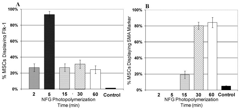
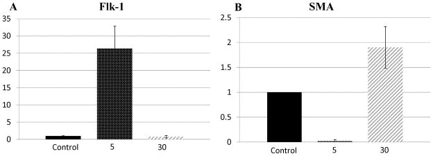
To determine whether MSC differentiations towards EC-like and SMC-like phenotypes were influenced by the 3D nanofiber elasticity, MSCs were cultured on NFGs photopolymerized for 2 min, 5 min, 15 min, 30 min and 60 min, respectively. After 24-hr of culture, the cells were stained with endothelial cell markers (FLK-1) and smooth muscle marker (SMA), and imaged on a fluorescent microscope. Results in Figure 8 showed that a minimum of 80% of the cells seeded on 30 min or 60 min NFGs demonstrate SMA markers, which is significantly greater than that of cells demonstrating SMA markers on 2, 5, and 15 min NFGs (p < 0.01). Also, 93% of the cells seeded on 5 min NFGs demonstrated FLK-1 markers, significantly greater (p < 0.01) than cells seeded on 2 min, 15 min, 30 min or 60 min NFGs. The control group demonstrated that less than 5% of MSCs seeded on petri dishes for 7 days demonstrated Flk-1 or SMA markers. To verify the results, the gene expression was examined. Real time PCR was performed on MSCs cultured for 24 hr on glass slides (control) and NFGs photopolymerized for 5 and 30 min, respectively. As shown in Figure 9, MSCs on 5 min NFGs showed a 25-fold increase in Flk-1 mRNA expression, when compared to the control. No significant increase or decrease in Flk-1 was found on 30 min NFGs, when compared to control. MSCs on 30 min NFGs show a 2-fold increase in SMA mRNA expression, when compared to control. MSCs on 5 min NFGs showed a 50-fold decrease in SMA mRNA expression, when compared to the control.
Figure 8.
(A) The percentage of MSCs demonstrating the Flk-1 marker when seeded on NFGs with various photopolymerization times. (B) The percentage of MSCs demonstrating the SMA marker when seeded on NFGs with various photopolymerization times. Vertical bars indicate standard deviation. For control cases, MSCs were seeded on petri dishes for 7 days. At the end of 7 days, cells were immunostained with Flk-1 and SMA markers.
Figure 9.
PCR data showing fold changes in MSC gene expression. (A) Fold changes in Flk-1 gene expression when MSCs are seeded on glass (control), and on NFGs photopolymerized for 5 and 30 min. (B) Fold changes in SMA gene expression when MSCs are seeded on glass (control), and on NFGs photopolymerized for 5 and 30 min. Vertical error bars show standard deviation. Flk-1 sample size n=3, SMA sample size n=3.
4. Discussion
Recent studies have highlighted the critical impacts of the elasticity of the cellular microenvironment on cell function and differentiation through replication of a native tissue’s elasticity [7]. A majority of the studies were shown with 2D substrates or 3D gels and related to bone, muscle or neural tissue [7, 21. 22]. By reproducing the modulus and structure of the cellular micro-environment found in the intima basal membrane and media with synthetic polymer matrix [11, 12], this study seeks to direct MSC differentiation into cells with vascular EC and SMC characteristics. We have fabricated a photopolymerizable 3D nanofibrous matrix by electrospinning a solution of PEGdma, PEO, and initiator. The elastic modulus can be controlled by varying the photopolymerization time, producing a matrix with tunable elasticity that ranges from 2 to 15 kPa, close to the modulus of the extracellular matrix in the in-vivo intima basement membrane or media layer. MSCs seeded on the nanofiber matrix result in a 3D tissue-like cell culture with the capability of differentiating into EC-like or SMC-like cells.
Cellular response is guided by three main categories of surface characteristics: topography, chemistry and elasticity [23]. Give the fact that SEM images of NFGs photopolymerized for 5 min and 30 min showed no significant differences in fiber diameter and matrix porosity, we conclude that there was minimal variation in NFG topography with increasing photopolymerization time. However, at the molecular level, a NFG photopolymerized for 5 min should have more uncrosslinked dimethacylite groups than a NFG photopolymerized for 30 min, resulting in variations in the molecular structure and surface chemistry between samples. One of the major mechanisms underlying influences of the surface chemistry on cellular responses is ligand density. Interestingly, previous studies [23, 24] have shown that the ligand density of a polymer surface does not vary significantly with the crosslinking density. Therefore, although it is not possible to eliminate deviations in the surface chemistry and topography while varying the substrate elasticity, we believe that the variation in elasticity is the dominating contributor to the MSC responses found in this study.
The elastic modulus of biomaterials significantly varies with loading mode, testing, and environmental conditions. To fully characterize the mechanical properties of these newly developed NFGs and to make comparisons between our results and others, several methods were used to analyze the mechanical properties of PEGdma/PEO matrices. As PEG is a highly hydrophilic material, tensile test of NFGs was performed in dry and hydrated conditions in order to understand the change in elasticity due to water exposure.
The blood vessel is characterized by a three-layer hierarchical structure with each layer composed of heterogeneous materials. Wagenseil and Mecham [14] utilized mechanical tests to determine the bulk modulus of the vessel wall, in which stiffer layers such as adventitial layer and media layer of the hierarchical structure likely make a major contribution. The purpose of this study is to examine how the elasticity of the local cellular microenvironments in the media and intima direct MSC differentiation into EC and SMC-like cells. Therefore, the local matrix moduli of separated vascular intima and media should be used as our references. For a heterogeneous, anisotropic material like the blood vessel, elasticity changes with testing method and resolution length scale. Thus researchers utilized compression test methods with nano and micro scale resolution, such as AFM indentation, to determine the local matrix elasticity of the cellular microenvironment. Additionally, a recent study has shown cells only sense the mechanical environment around them up to a depth of 5 microns [25]. Collectively, it is critical for us to replicate the local modulus of the cellular microenvironment found in the intima and media, respectively. Because our material is homogeneous and isotropic, it is reasonable to infer the local compression modulus from bulk compression testing. Compression tests demonstrated the span of NFG elasticity, and indicate the NFG elasticity is in the range of the elasticity of the in-vivo intima and media characterized in the literature [12,6]. Our compression and tensile tests did not offer sufficient resolution to fully characterize the differences in elasticity due to variations in photopolymerization time. As a common method to characterize differences in the bulk storage modulus of a hydrogel [26], rheology test was further performed. Comparison of the storage moduli in the linear viscoelastic region of nanofiber grafts with 2, 5, 15, 30, and 60 min photopolymerization times showed statistically different storage moduli between samples, revealing the fold differences in modulus with photopolymerization time. Furthermore, this data confirms the expected increase in modulus with increasing photopolymerization time.
In this study, MSCs seeded on NFGs readily penetrated into the graft resulting in cell culture in the 3D fibrous matrix within 24 hr of seeding. It is likely the collagen molecules coating the graft cover the entire 3D fibrous matrix, allowing cellular penetration and adherence to the 3D matrix within 24 hr. Past research has shown cell adhesion, morphology, differentiation and migration vary greatly when seeded on a 2D substrate, a 3D gel, and a 3D fibrous matrix [27, 28]. Our results showed that MSC area increased with increasing NFG modulus. MSCs in softer matrices exhibit less polarized morphology whereas MSCs in stiffer matrices demonstrate a more striated morphology and larger cell area. All of these elasticity-dependent morphology changes correlated well with MSC spreading results on previous studies on 2D hydrogels by Engler, Evans and Park [7, 29, 30]. Recently, it was shown MSCs encapsulated for 14 days in highly crosslinked, less degradable 3D gels were confined, thus forming spherical shapes whereas MSCs in less crosslinked, more degradable 3D gels developed a well-spreaded morphology [28]. The various cellular morphology trends seen in these studies as well as our work highlight the importance of spatial mechanisms on cellular behavior. We believe the high porosity of a 3D nanofiber matrix allows cells to spread. Thus, in highly porous and stable nanofiber matrices, as those presented here and those in the natural vascular matrix environment, cell spreading increases with increasing matrix elasticity. To determine if the morphological changes also resulted in a divergence in cell differentiation, we examined MSCs for the expression of EC marker (Flk-1) and SMC marker (SMA). Immunostaining results demonstrated an upregulation of Flk-1+ cells only on NFGs that have been photopolymerized for 5 min. This data was somewhat surprising, as rheology testing indicated there were small fold differences in elasticity between NFGs photopolymerized for 5 min and those for 2 or 15 min. A recent study by Byfield et al [22] demonstrated that EC seeded in a 3D gel are sensitive to changes in substrate elasticity as low as 400 Pa, responding with variations in actin density and cell morphology. Therefore, it is possible that endothelial markers are only upregulated by a 3D matrix whose elasticity falls in a very narrowed range. Substrates that have been photopolymerized for 5 min have a compressive modulus of roughly 2–3 kPa, in the range of the modulus of the in-vivo endothelial basement membrane [12]. Our results also correlated well with a previous study done by Zhang et al [31] who found MSC differentiation into vascular cells with endothelial markers on 3D fibrin matrices with a storage modulus of 100 Pa. Furthermore, our results also showed an upregulation of SMA+ cells on NFGs that have been photopolymerized for 30 min and 60 min (compressive modulus of 12–15 kPa), which correlated well with findings by S Park et al on a 2D gel [30]. Our immunostaining data was further confirmed with real time PCR analysis, where MSCs seeded on 5 min NFGs for 24 hr showed a 22-fold increase of Flk-1 mRNA expression when compared to MSCs seeded on glass controls or 30 min NFGs. MSCs on 30 min NFGs showed a 2-fold increase in SMA mRNA expression when compared to MSCs on glass controls, and a 96-fold increase in SMA mRNA expression when compared to MSCs seeded on 5 min NFGs. After only 24 hr, MSCs showed different responses to 3D fibrous environments with diverse moduli. The upregulation of these early-stage vascular markers indicate that MSC differentiation towards a specific vascular cell or lineage commitment to EC or SMC may be controlled by carefully designing the modulus of the fibrous matrix.
5. Conclusions
In conclusion, mechanically tunable 3D nanofibrous matrices have been developed utilizing electrospinning and photopolymerization techniques. Matrices with varying moduli in the range of 2 to 15 kPa were used to determine the preferred mechanical microenvironment for MSC to EC and MSC to SMC differentiation. Variations in MSC spreading and vascular SMA and Flk-1 markers and mRNA expression in correlation with NFG elasticity were found after only 24 hr of cell seeding. These findings suggest lineage commitment of MSCs towards specific vascular cells can be controlled by carefully designing the substrate modulus.
Acknowledgments
The authors would like to thank Dr. Luftig for his assistance with statistical analysis, Dr Devon Scott for her assistance with immunofluorescent staining, Dr Stephanie LaNasa, Mark Swartzlander, and Stacey Skaalure for their assistance with polymer fabrication. Dr Dongjie Guo at Nanjing University of Aeronautics and Astronautics for his help with FTIR analysis. Dr Chris Bowman and Dr. Brian Adzima for their assistance with rheometer testing. The research is partly funded by NIH (NHLBI 097246-01 to W.T) and State of Colorado (Biodiscovery Program to W.T.).
Footnotes
Publisher's Disclaimer: This is a PDF file of an unedited manuscript that has been accepted for publication. As a service to our customers we are providing this early version of the manuscript. The manuscript will undergo copyediting, typesetting, and review of the resulting proof before it is published in its final citable form. Please note that during the production process errors may be discovered which could affect the content, and all legal disclaimers that apply to the journal pertain.
Contributor Information
Kathryn Wingate, Email: kathryn.wingate@colorado.edu.
Walter Bonani, Email: walter.bonani@colorado.edu.
Yan Tan, Email: tanyangdmc@yahoo.com.cn.
Stephanie J. Bryant, Email: stephanie.bryant@colorado.edu.
Wei Tan, Email: wtan@colorado.edu.
References
- 1.Lith R, Ameer GA. Tissue Engineering. Springer; Berlin Heidelberg: 2011. Biohybrid strategies for vascular grafts; pp. 279–316. [Google Scholar]
- 2.Pawlowski KJ, Rittgers SE, Schmidt SP, Bowlin GL. Front biosci. 2004;9:1412–1421. doi: 10.2741/1302. [DOI] [PubMed] [Google Scholar]
- 3.Nieponice A, Soletti L, Guan J, Deasy BM, Huard J, Wagner WR, Vorp DA. Biomaterials. 2008;29:825–833. doi: 10.1016/j.biomaterials.2007.10.044. [DOI] [PMC free article] [PubMed] [Google Scholar]
- 4.Park J, Huang N, Kurpinski K, Patel S, Hsu S, Li S. Frontiers in bioscience. 2007;12:5098–5116. doi: 10.2741/2551. [DOI] [PubMed] [Google Scholar]
- 5.Kan I, Melamed E, Offen D. Curr drug targets. 2005;6:31–41. doi: 10.2174/1389450053344902. [DOI] [PubMed] [Google Scholar]
- 6.Wong J, Velasco A, Rajagopalan P, Pham Q. Langmuir. 2003;19:1908–1913. [Google Scholar]
- 7.Engler A, Sen S, Sweeney H, Discher D. Cell. 2006;126:677–689. doi: 10.1016/j.cell.2006.06.044. [DOI] [PubMed] [Google Scholar]
- 8.Cukierman E, Pankov R, Stevens DR, Yamada KM. Science. 2001;294:1708–1712. doi: 10.1126/science.1064829. [DOI] [PubMed] [Google Scholar]
- 9.Xu CY, Inai R, Kotaki M, Ramakrishna S. Biomaterials. 2004;25:877–886. doi: 10.1016/s0142-9612(03)00593-3. [DOI] [PubMed] [Google Scholar]
- 10.Tan AR, Ifkovits JL, Baker BM, Brey DM, Mauck RL, Burdick JA. J biomed mater res a. 2008;87:1034–1043. doi: 10.1002/jbm.a.31853. [DOI] [PMC free article] [PubMed] [Google Scholar]
- 11.Richert L, Wong J, Picart C, Discher D, Engler A. Departmental papers (cbe) 2004 [Google Scholar]
- 12.Peloquin J, Huynh J, Williams RM, Reinhart-King CA. Journal of biomechanics. 2011;44:815–821. doi: 10.1016/j.jbiomech.2010.12.018. [DOI] [PubMed] [Google Scholar]
- 13.Bou-Gharios G, Ponticos M, Rajkumar V, Abraham D. Cell prolif. 2004;37:207–220. doi: 10.1111/j.1365-2184.2004.00306.x. [DOI] [PMC free article] [PubMed] [Google Scholar]
- 14.Wagenseil JE, Mecham RP. Physiol rev. 2009;89:957–989. doi: 10.1152/physrev.00041.2008. [DOI] [PMC free article] [PubMed] [Google Scholar]
- 15.Lin-Gibson S, Bencherif S, Cooper JA, Wetzel SJ, Antonucci JM, Vogel BM, Horkay F, Washburn NR. Biomacromolecules. 2004;5:1280–1287. doi: 10.1021/bm0498777. [DOI] [PubMed] [Google Scholar]
- 16.Winer BJ, Brown DR, Michels KM. Statistical Principles in Experimental Design. McGraw-Hill; 1991. [Google Scholar]
- 17.Hwang NS, Varghese S, Li H, Elisseeff J. Cell tissue res. 2011;344:499–509. doi: 10.1007/s00441-011-1153-2. [DOI] [PubMed] [Google Scholar]
- 18.Ifkovits JL, Burdick JA. Tissue eng. 2007;13:2369–2385. doi: 10.1089/ten.2007.0093. [DOI] [PubMed] [Google Scholar]
- 19.LaNasa SM, Hoffecker IT, Bryant SJ. Journal of biomedical materials research part b: applied biomaterials. 2011;96B:294–302. doi: 10.1002/jbm.b.31765. [DOI] [PubMed] [Google Scholar]
- 20.Ma PX, Elisseeff JH. Scaffolding in Tissue Engineering. CRC Press; 2005. [Google Scholar]
- 21.Sieminski AL, Hebbel RP, Gooch KJ. Exp cell res. 2004;297:574–584. doi: 10.1016/j.yexcr.2004.03.035. [DOI] [PubMed] [Google Scholar]
- 22.Byfield FJ, Reen RK, Shentu T-P, Levitan I, Gooch KJ. J biomech. 2009;42:1114–1119. doi: 10.1016/j.jbiomech.2009.02.012. [DOI] [PMC free article] [PubMed] [Google Scholar]
- 23.Wong Leach J, Brown X. Surface science. 2004;570:119–133. [Google Scholar]
- 24.Engler A, Bacakova L, Newman C, Hategan A, Griffin M, Discher D. Biophysical journal. 2004;86:617–628. doi: 10.1016/S0006-3495(04)74140-5. [DOI] [PMC free article] [PubMed] [Google Scholar]
- 25.Buxboim A, Rajagopal K, Brown AEX, Discher DE. J phys condens matter. 2010:22. doi: 10.1088/0953-8984/22/19/194116. [DOI] [PMC free article] [PubMed] [Google Scholar]
- 26.Kloxin AM, Kloxin CJ, Bowman CN, Anseth KS. Advanced materials. 2010;22:3484–3494. doi: 10.1002/adma.200904179. [DOI] [PMC free article] [PubMed] [Google Scholar]
- 27.Lawrence BJ, Madihally SV. Cell adh migr. 2008;2:9–16. doi: 10.4161/cam.2.1.5884. [DOI] [PMC free article] [PubMed] [Google Scholar]
- 28.Khetan S, Burdick JA. Biomaterials. 2010;31:8228–8234. doi: 10.1016/j.biomaterials.2010.07.035. [DOI] [PubMed] [Google Scholar]
- 29.Evans ND, Minelli C, Gentleman E, LaPointe V, Patankar SN, Kallivretaki M, Chen X, Roberts CJ, Stevens MM. Eur cell mater. 2009;18:1–13. doi: 10.22203/ecm.v018a01. discussion 13–14. [DOI] [PubMed] [Google Scholar]
- 30.Park JS, Chu JS, Tsou AD, Diop R, Tang Z, Wang A, Li S. Biomaterials. 2011;32:3921–3930. doi: 10.1016/j.biomaterials.2011.02.019. [DOI] [PMC free article] [PubMed] [Google Scholar]
- 31.Zhang G, Drinnan CT, Geuss LR, Suggs LJ. Acta biomater. 2010;6:3395–3403. doi: 10.1016/j.actbio.2010.03.019. [DOI] [PubMed] [Google Scholar]


