BACKGROUND
The Taylor Spatial Frame (TSF; Smith & Nephew Inc, Memphis, Tennessee, US) is a circular external fixator with two rings or partial rings connected by six telescopic struts used to correct limb deformities using an internet-based computer program. The use of six-axis deformity analysis allows correction of multi-planar skeletal deformities. The surgeon must define: the deformity in the anteroposterior (AP), lateral and axial planes; the mounting parameters of the rings; the lengths of the six struts; and the correction time.
We describe a simple and efficient way of calculating the mounting parameters for the TSF in the operating theatre using fiuoroscopic image intensifier pictures.
TECHNIQUE
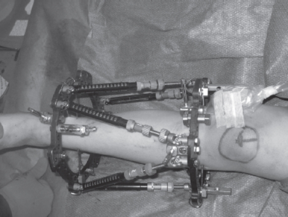
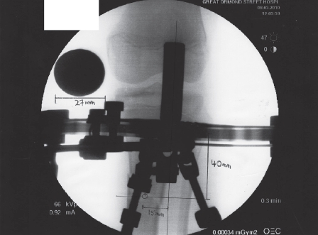
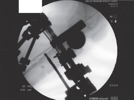
Once the TSF has been applied, the image intensifier is used to take images of the limb orthogonal to the reference ring of the TSF. We use a sterilised spherical stainless steel ball (30mm diameter) as a calibration device applied to the surface of the limb. The calibration ball can be wrapped in a clear sterile plastic sheet (eg an arthroscopic plastic sheath) and taped to the limb with Steri-Strips™ (Fig. 1). A 50mm post is placed in the central hole of the main tab on the reference ring with another 50mm post placed directly opposite on the posterior portion of the ring. Using the posts as a guide, AP orthogonal views are obtained when the ring is flat and the posts are superimposed (Fig. 2). The same posts are then placed in the hole exactly halfway between the anterior and posterior main tabs on either side. Lateral orthogonal views are obtained when the ring is flat and the posts are superimposed (Fig. 3).
Figure 1.

Photograph showing the Taylor Spatial Frame with 50mm posts (located medial and lateral) and a calibration ball placed in a sterile plastic sheath.
Figure 2.

Fluoroscopic anteroposterior view showing 50mm posts.
Figure 3.

Fluoroscopic lateral view showing superimposed 50mm posts.
The mounting parameters define the position of the centre of the reference ring in relation to the origin of the deformity. The three mounting parameters are:
in the AP view the distance of the centre of the ring medial or lateral from the origin;
in the AP view the distance of the centre of the ring proximal or distal from the origin; and
in the lateral view the distance of the centre of the ring anterior or posterior to the origin.
The surgeon calculates the mounting parameters for the reference ring from the printed pictures. Using the example in Figure 2, a line bisecting the posts is extended longitudinally, indicating the centre of the ring. The distance from the origin to this line is the AP frame offset. The steel ball measures 27mm in the AP view. Therefore, adjusting for magnification, the AP frame offset is: 15mm (lateral) × 30mm / 27mm = 17mm lateral to origin (rounded off to the nearest mm). The axial frame offset is: 40mm (proximal) × 30mm / 27mm = 44mm proximal to origin (rounded off to the nearest mm).
The lateral frame offset is calculated in a similar manner, using the lateral view images to measure the distance of the ring to the origin and adjusting for magnification as above.
DISCUSSION
Calculating the mounting parameters in theatre using the image intensifier has several advantages. The surgeon can ensure that appropriate orthogonal images are obtained centring on the correct ring. This eliminates the need for postoperative radiographs and repeat radiographs if the views are unsatisfactory and reduces the radiation exposure to the patient. Inputting the mounting parameters directly into the computer program in theatre also allows the strut prescription to be calculated and for the surgeon to change struts if necessary.


