Abstract
In this paper, in order to improve the efficiency of dye-sensitized solar cells, we introduced zirconia [ZrO2] nanofibers into a mesoporous titania [TiO2] photoelectrode. The photoelectrode consists of a few weight percent of ZrO2 nanofibers and a mesoporous TiO2 powder. The mixed ZrO2 nanofibers and the mesoporous TiO2 powder possessed a larger surface area than the corresponding mesoporous TiO2 powder. The optimum ratio of the ZrO2 nanofiber was 5 wt.%. The 5 wt.% ZrO2-mixed device could get a short-circuit photocurrent density of 15.9 mA/cm2, an open-circuit photovoltage of 0.69 V, a fill factor of 0.60, and a light-to-electricity conversion efficiency of 6.5% under irradiation of AM 1.5 (100 mW/cm2).
Keywords: zirconia nanofiber, titania, DSSC
Introduction
Dye-sensitized solar cells [DSSCs] have generated a considerable research interest because of their high-energy conversion efficiency (approximately 11%) and low production costs [1-3]. A typical DSSC device contains a light-harvesting layer on a photoelectrode and a Pt-coated layer on a counter electrode; both electrodes are made of a transparent conducting oxide substrate; an iodine-based electrolyte fills the space between the photoelectrode and the counter electrode to serve as a redox mediator in a sandwich-type structure. Performance of the DSSC depends on many factors such as the TiO2 surface morphology, particle size, thickness of the photoelectrode, nature of the dye, etc. [4-10].
A high light-to-electricity conversion efficiency results from a large surface area of the mesoporous TiO2 photoelectrode, on which the dyes can be sufficiently adsorbed. In this study, we introduced zirconia [ZrO2] nanofibers into the mesoporous titania [TiO2] photoelectrode. The ZrO2 nanofibers are prepared by electrospinning. The TiO2 film composite with ZrO2 nanofibers creates a larger surface area than the single TiO2 film, in which case the amount of dye loading was increased and short-circuit photocurrent density and solar conversion efficiency are also increased.
Experimental details
The ZrO2 nanofiber additives were prepared by electrospinning method. At first, mixed together, 6 ml zirconium acetate, 12 ml acetic acid, 12 ml ethanol, and 50 g poly(methyl methacrylate) were stirred for 24 h; then, the compounds were sintered at 700°C for 4 h. A detailed process is displayed in Figure 1.
Figure 1.
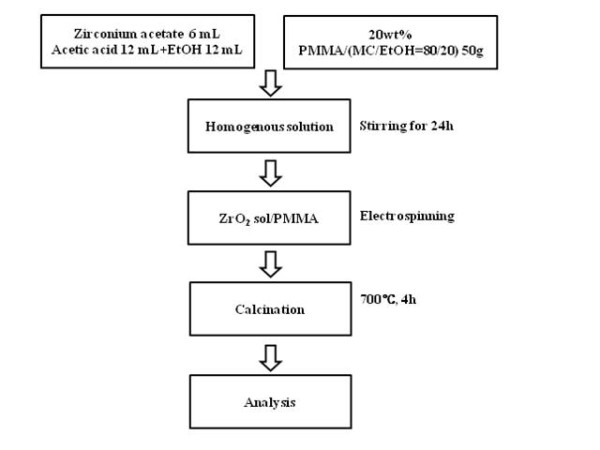
Preparation of the ZrO2 nanofiber.
The TiO2 paste was prepared by mixing TiO2 with Degussa P-25, polyethylene glycol, acetyl acetone, distilled water, triton X-100, HNO3, and ZrO2 nanofibers. The concentrations of ZrO2 nanofibers were 0, 3, 5, and 7 wt.%. The mixed solutions were ball milled at 100 rpm for 10 h. The photoelectrode was fabricated using a clean fluorine-doped tin dioxide [FTO] (approximately 8 Ω/cm2, Pilkington conductive glass, Seoul, South Korea) by squeeze printing. The coated photoelectrode was heat treated at 450°C for 30 min with a heating rate of 5°C/min. The obtained photoelectrode was immersed into the ethanol solution containing [cis-diisothiocyanato-bis(2,2'-bipyridyl-4,4'-dicarboxylato)ruthenium(II) bis(tetrabutylammonium)] (N719 dye, Solaronix, Aubonne, Switzerland) for 24 h. The active area of the photoelectrode was 0.5 × 0.5 cm2. On the other hand, the counter electrode was prepared similar to the photoelectrode preparation. Pt-Sol (Pt catalyst/SP, Solaronix) was coated onto the FTO glass by the squeeze printing method. The coated paste was heat treated at 450°C for 30 min with a heating rate of 5°C/min.
The electrolyte solution consisted of 0.3 M 1,2-dimethyl-3-propylimidazolium iodide, 0.5 M Li(I), 0.05 M I2, and 0.5 M 4-t-butylpyridine in 3-methoxypropionitrile between the two electrodes. The dye-coated photoelectrode and the Pt-coated counter electrode were sandwiched using a 60-μm-thick hot-melt sealing foil (SX 1170-60, Solaronix).
The field-emission scanning electron microscope [FE-SEM] (S-4700, Hitachi, Seoul, South Korea) and BET were used to examine the morphology and the pore distribution volume of the TiO2 film. In order to investigate the physical and optical characteristics of the dye-adsorbed TiO2 films, the UV-visible [UV-Vis] spectrum measurement was performed. The photovoltaic properties were investigated by measuring the photocurrent-voltage characteristics under illumination with air mass [AM] 1.5 (100 mW/cm2) simulated sunlight.
Results and discussion
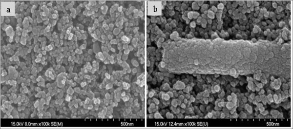
Figure 2 shows the FE-SEM images of the TiO2 film's surface and the 5 wt.% ZrO2 nanofiber-added TiO2 film's surface. In the ZrO2 nanofiber-added TiO2 film in Figure 2b, the ZrO2 nanofiber was shown at the surface of the TiO2 film, or the TiO2 film was studded with the ZrO2 nanofiber. The TiO2 film's surface area was increased, and the dye adsorption contents became larger by the addition of the ZrO2 nanofiber. So, we can forecast that the TiO2 electrode is able to obtain high conversion efficiency.
Figure 2.
FE-SEM images of (a) TiO2 film and (b) 5 wt.% ZrO2 nanofiber-doped TiO2 film.
Figure 3 shows the pore distributions calculated from adsorption data using the Barrett-Joyner-Halenda [BJH] method. As shown in Figure 3, a broad peak was found at around 25 nm, and an added 5 wt.% ZrO2 nanofiber at around 30 nm was observed. Compared to the pure TiO2 film, the 5 wt.% ZrO2 nanofiber-added TiO2 films show a significant change in the pore size distribution. A large pore volume in BJH was observed on the TiO2 film with 5 wt.% ZrO2 nanofibers, which is in agreement with the results of the FE-SEM image.
Figure 3.
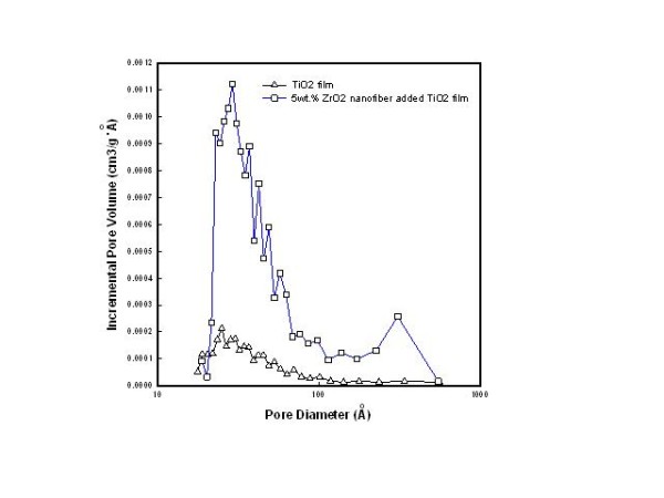
BJH curve of TiO2 film (triangle) and 5 wt.% ZrO2 nanofiber-doped TiO2 film (square).
Figure 4 shows the UV-Vis absorption spectra of the dye-adsorbed TiO2 film and the 3, 5, and 7 wt.% ZrO2 nanofiber-doped TiO2 films. From the results, the absorption spectra increased at around 538 nm with added ZrO2 nanofibers doped in the TiO2 film and also enhanced the amount of dye loading. So, the 5 wt.% ZrO2 nanofiber-doped TiO2 film had the best dye loading, and also, its solar conversion efficiency was the best among the samples.
Figure 4.
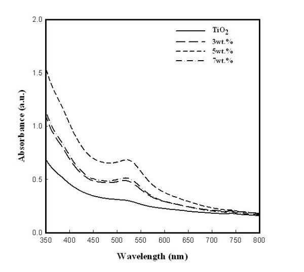
UV-Vis spectrum of TiO2 film and ZrO2 nanofiber-doped TiO2 film after 24-h dye absorption.
In order to determine the factors that influence the stability of the DSSCs, electrochemical impedance spectroscopy [EIS] was performed. Figure 5 shows that the Nyquist plot of EIS of the DSSCs exhibits semicircles, which are assigned to the electrochemical reaction at the Pt counter electrode, the charge transfer at the TiO2/dye/electrolyte interface, and the Warburg diffusion process of I-/I3- [9,10]. As shown in Figure 5, the second semicircle is the resistance (R2) related to the electron transport in the TiO2/dye/electrolyte interface which is reduced. It can be seen that the TiO2 film and the 3, 5, and 7 wt.% ZrO2 nanofiber-doped TiO2 films are 13.2, 10.3, 9.6, and 11.9 Ω, respectively.
Figure 5.
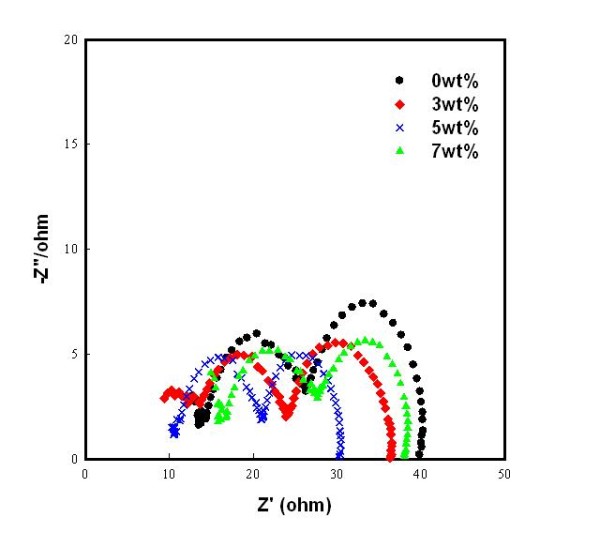
Nyquist plots of the DSSCs using TiO2 film and ZrO2 nanofiber-doped TiO2 film. Black circle, 0 wt.%; red diamond, 3 wt.%; cross mark, 5 wt.%; green triangle, 7 wt.%.
Figure 6 shows photocurrent-voltage characteristics of the DSSCs with the ZrO2 nanofiber-doped TiO2 film. The open-circuit photovoltage was almost the same, and the short-circuit photocurrent density increased with the added amount of ZrO2 nanofibers and had reached the maximum at 5 wt.% of ZrO2 nanofiber (15.9 mA/cm2). The open-circuit photovoltage [Voc], the short-circuit photocurrent density [Jsc], the fill factor [FF], and the light-to-electricity conversion efficiency [η] at 5 wt.% added ZrO2 nanofiber were 0.69 V, 15.9 mA/cm2, 0.60, and 6.5%, respectively, as shown in Table 1. From the results, we can realize that the insertion of ZrO2 nanofibers creates a larger surface area and reduces the resistance of the photoelectrode, especially for the optimal amount of ZrO2 contents (7 wt.%) of the photoelectrode in DSSCs.
Figure 6.
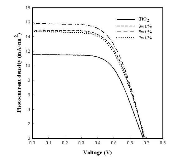
Photocurrent-voltage curve of the TiO2 film and the TiO2 films with ZrO2 nanofibers.
Table 1.
Photocurrent-voltage characteristics of DSSCs using TiO2 with different amounts of ZrO2 nanofibers
| Sample | Voc (V) | Jsc (mA/cm2) | FF | η (%) |
|---|---|---|---|---|
| Pure TiO2 | 0.68 | 11.5 | 0.62 | 4.9 |
| 3 wt.% ZrO2 nanofiber-doped TiO2 | 0.69 | 14.9 | 0.60 | 6.2 |
| 5 wt.% ZrO2 nanofiber-doped TiO2 | 0.69 | 15.9 | 0.60 | 6.5 |
| 7 wt.% ZrO2 nanofiber-doped TiO2 | 0.69 | 14.7 | 0.59 | 6.0 |
Voc, open-circuit photovoltage; Jsc, short-circuit photocurrent density; FF, fill factor; η, light-to-electricity conversion efficiency; TiO2, titania; ZrO2, zirconia.
Conclusions
In summary, a ZrO2 nanofiber-doped TiO2 film was used as a photoelectrode in DSSCs. The ZrO2 nanofiber-doped TiO2 films had a larger surface area than the pure TiO2 film, in which case the amount of dye loading was increased, and Jsc and η were also increased. The optimum ratio of the ZrO2 nanofiber was 5 wt.%. The DSSC with the 5 wt.% ZrO2 nanofiber photoelectrode provided the highest η of 6.5%, Jsc of 15.9 mA/cm2, Voc of 0.69 V, and FF of 0.60 under AM 1.5 (100 mW/cm2) simulated sunlight illumination. Therefore, ZrO2 fibers are a promising additive for the realization of high-efficiency DSSCs.
Competing interests
The authors declare that they have no competing interests.
Authors' contributions
JW fabricated the DSSCs and UV-Vis analysis. EMJ was the paper chaser and performed the analysis of photocurrent-voltage characteristics and impedance. WLW performed the BET analysis. J-YP prepared the ZrO2 nanofibers. XGZ performed the FE-SEM analysis. H-BG was thesis director. All authors read and approved the final manuscript.
Contributor Information
Jiao Wang, Email: wangjiao1984@hotmail.com.
En Mei Jin, Email: kujie@naver.com.
Ju-Young Park, Email: g0m8812@hanmail.net.
Wan Lin Wang, Email: kuku-linlin@hotmail.com.
Xing Guan Zhao, Email: xingguan424@naver.com.
Hal-Bon Gu, Email: hbgu@chonnam.ac.kr.
References
- O'Regan B, Grätzel M. A low-cost, high-efficiency solar cell based on dye-sensitized colloidal titanium dioxide films. Nature. 1991;335:737–740. [Google Scholar]
- Nazeeruddin MK, Kay A, Rodicio I, Humphry R, Muller E, Liska P, Vlachopoulos N, Grätzel M. Conversion of light to electricity by cis-X2bis(2,2'-bipyridyl-4,4'-dicarboxylate (ruthenium(II) charge transfer sensitizers)X = Cl-, Br1, I-, Cn-, and SCN-) on nanocrystalline titanium dioxide electrodes. J Am Chem Soc. 1993;115:6382–6390. doi: 10.1021/ja00067a063. [DOI] [Google Scholar]
- Hore S, Vetter C, Kern R, Smit H, Hinsch A. Influence of scattering layers on efficiency of dye-sensitized solar cells. Sol Energy Mater. 2006;90:1176–1188. doi: 10.1016/j.solmat.2005.07.002. [DOI] [Google Scholar]
- Park K, Gu H, Jin EM, Dhayal M. Using hybrid silica-conjugated TiO2 nanostructure to enhance the efficiency of dye-sensitized solar cells. Electrochimica Acta. 2010;55:5499–5505. doi: 10.1016/j.electacta.2010.04.100. [DOI] [Google Scholar]
- Ito Seigo, Kitamura Takayuki, Wada Yuji, Yanagida Shozo. Facile fabrication of mesoporous TiO2 electrodes for dye solar cells: chemical modification and repetitive coating. Solar Energy Mater Solar Cells. 2003;76:3–13. doi: 10.1016/S0927-0248(02)00209-X. [DOI] [Google Scholar]
- Jin EM, Park K, Yun J, Hong CK, Hwang M, Park B, Kim K, Gu H. Photovoltaic properties of TiO2 photoelectrode prepared by using liquid PEG-EEM binder. Surface Rev Lett (SRL) 2010;17:15–20. doi: 10.1142/S0218625X10013576. [DOI] [Google Scholar]
- Park KH, Jin EM, Gu HB, Shim SE, Hong CK. Effects of HNO3 treatment of TiO2 nanoparticles on the photovoltaic properties of dye-sensitized solar cells. Mater Lett. 2009;63:2208–2211. doi: 10.1016/j.matlet.2009.07.034. [DOI] [Google Scholar]
- Chou Chuen-Shii, Yang Ru-Yuan, Yeh Cheng-Kuo, Lin You-Jen. Preparation of TiO2/nano-metal composite particles and their applications in dye-sensitized solar cells. Powder Technol. 2009;194:95–105. doi: 10.1016/j.powtec.2009.03.039. [DOI] [Google Scholar]
- Fabregat-Santiago F, Bisquert J, Garcia-Belmonte G, Boschloo G, Hagfeldt A. Influence of electrolyte in transport and recombination in dye-sensitized solar cells studied by impedance spectroscopy. Solar Ener Mat Solar Cells. 2005;87:117–131. doi: 10.1016/j.solmat.2004.07.017. [DOI] [Google Scholar]
- Koide Naoki, Islam Ashraful, Chiba Uasou, HAn Liyuan. J Photochem Photobiol A: Improvement of efficiency of dye-sensitized solar cells based on analysis of equivalent circuit. Chem. 2006;182:296–305. [Google Scholar]


