Abstract
The purpose of this study was to develop a technique to measure the dielectric properties of biological tissues with an interstitial dipole antenna based upon previous efforts for open-ended coaxial probes. The primary motivation for this technique is to facilitate treatment monitoring during microwave tumor ablation by utilizing the heating antenna without additional intervention or interruption of the treatment. The complex permittivity of a tissue volume surrounding the antenna was calculated from reflection coefficients measured after high-temperature microwave heating by using a rational function model of the antenna’s input admittance. Three referencing liquids were needed for measurement calibration. The dielectric measurement technique was validated ex vivo in normal and ablated bovine livers. Relative permittivity and effective conductivity were lower in the ablation zone when compared to normal tissue, consistent with previous results. The dipole technique demonstrated a mean 10% difference of permittivity values when compared to open-ended coaxial cable measurements in the frequency range of 0.5–20 GHz. Variability in measured permittivities could be smoothed by fitting to a Cole–Cole dispersion model. Further development of this technique may facilitate real-time monitoring of microwave ablation treatments through the treatment applicator.
Keywords: Antenna, dielectric, microwave ablation
I. Introduction
THERMAL ablation is gaining acceptance as a method to treat hepatic tumors in patients who cannot be treated by surgery. While RF energy is the current clinical standard in high-temperature ablation, microwaves offer several additional benefits for tissue heating, including the ability to penetrate through charred or desiccated tissue, faster temperature elevation, and higher internal temperatures, leading to larger and more consistent zones of ablation [1]. In ablative procedures, the goal is to heat the tumor volume plus a 5–10 mm radial margin of seemingly normal tissue beyond a lethal threshold (typically 50 °C). Erroneous placement of the ablation applicator can result in undertreatment, local recurrence, or excessive damage to surrounding tissue [2]. For these reasons, an accurate, real-time monitoring technique to verify treatment progress and predict technical success is required. Current monitoring techniques include ultrasound imaging with and without contrast enhancement, immediate postablation contrast-enhanced computed tomography (CT), magnetic resonance imaging (MRI), or thermal imaging (MRTI). However, these techniques are associated with relative drawbacks such as poor visualization of the true ablation zone, use of potentially harmful ionizing radiation, high financial cost, technical complexity, or the use of contrast agents that may not be suitable in all patient populations.
Recently, a technique has been developed to estimate the distance between an interstitial microwave ablation antenna and surrounding dielectric boundaries by analyzing peaks in the time-domain reflection coefficient of the antenna [3]. That study considered differences in the relative permittivity between tumor and background tissue, but substantial changes in relative permittivity also occur in tissues heated to ablative temperatures [4], [5]. These changes appear to relate primarily to the content and state of water in the tissue (free or bound), the dielectric relaxation of proteins, and the Maxwell–Wagner relaxation (relaxation due to the charging of the cell membranes) [6]. Therefore, we hypothesize that these changes may provide sufficient dielectric contrast to allow monitoring of time-domain peaks in the reflection coefficient and, hence, monitoring of ablation zone growth through the heating antenna itself.
The technique of [3] requires an assumption of wave speed in the ablated volume. Since wave speed is related to relative permittivity, and is frequency dependent, more accurate estimation of dielectric properties in the ablated volume would facilitate more accurate estimation of the ablation diameter. Therefore, the objective of this study was to develop a technique that will allow such dielectric property estimation by using only the heating antenna. In addition, we anticipate that the ability to measure dielectric properties around the heating antenna may facilitate an improved understanding of the basic biophysical interaction mechanisms of electromagnetic fields with living matter or facilitate thermal dosimetric calculations since the effective tissue conductivity is involved in the calculation of specific absorption rate (SAR).
II. Method
A. Overview
There has been significant interest in using interstitial coaxial dipole or slot antennas for microwave thermal ablation (see Fig. 1) [7], but little development of dielectric measurement has been carried out with such a device. However, open-ended coaxial probes have been investigated thoroughly for noninvasive dielectric measurement in biological materials [8], [9]. The open end of the probe is placed in contact with the material under test, the reflection coefficient is measured, and it is used with arational function model to calculate thecomplex permittivity of the material (see Fig. 2).
Fig. 1.

Geometry of the insulated coaxial dipole antenna. Electromagnetic energy is fed through a small annular gap hgap and radiates into the surrounding tissue from the tip hA and outer surface of the coaxial feed line. Tissue is electromagnetically lossy, and is characterized by a complex relative permittivity.
Fig. 2.
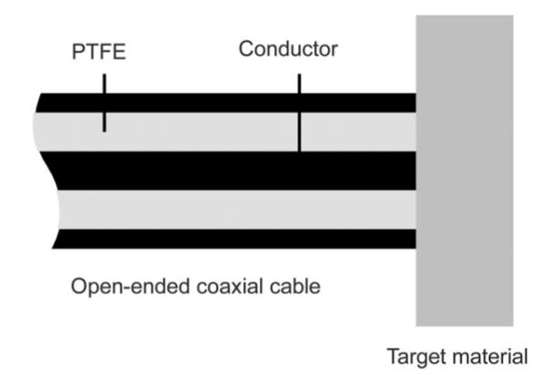
Geometry of an open-ended coaxial sensor. Fields emanating from the annulus at the open end interact with the tissue in a relatively small measurement volume, allowing precise measurement of the tissue dielectric properties at microwave frequencies.
By applying similar formulations, the permittivity around the heating antenna may be computed as well. A major difference between the two structures is that the antenna has a much larger sensing region, which is ellipsoidal around the feed gap. The radiated energy density is greatest near the fed gap and decreases monotonically in the radial direction. Therefore, as with the open-ended coaxial probe, materials closer to the fed gap have more impact on the sensed reflection values. We anticipate that measurements with the antenna will have a lower spatial resolution and, hence, incorporate greater variability in tissue properties. Therefore, we hypothesized that the approximate weighted average permittivity in the ablation zone can be measured from the ablation antenna.
B. Antenna Design and Feasibility Analysis
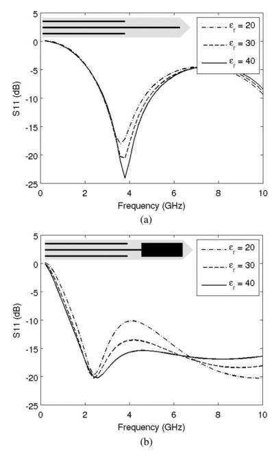
For the purpose of dielectric measurement, the antenna should exhibit some amount of sensitivity in reflection coefficient with respect to the permittivity values of the ambient medium. Fig. 3 plots the reflection coefficients S11 of two types of insulated coaxial antenna: monopole and dipole, with the geometry of 2.2 mm in diameter and 1.2 cm in tip length. The data were computed from the transmission line model with the ambient permittivity values of 20, 30, and 40, respectively [10]. It can be seen that the monopole antenna exhibits lower sensitivity to the ambient medium permittivity than the dipole antenna. No apparent sensitivity exists for the frequencies under 3 GHz. Therefore, because of its relatively low return loss and moderate sensitivity to dielectric changes in the surrounding tissue, the insulated coaxial dipole antenna was chosen for this study.
Fig. 3.
Reflection coefficients of insulated coaxial antenna versus frequency with respect to ambient relative permittivity values: 20, 30, and 40. The monopole antenna is less sensitive to changes in the surrounding tissue properties, so the dipole design was selected for this study. (a) Coaxial monopole antenna and (b) coaxial dipole antenna.
Dipole antennas were constructed from semirigid coaxial cable (UT-085 C, MICRO-COAX, Pottstown, PA), using a tip length, hA = 1.2 cm, gap width, hGap = 1mm, and diameter of outer conductor, 2a = 2.2 mm (see Fig. 1). Antennas were covered with about 0.3-mm-thick polyolefin heat-shrink tubing (7856K673, Mcmaster-Carr, Robbinsville, NJ). The geometry was chosen based on low reflection coefficient at 2.45 GHz of microwave power, appropriate SAR pattern for thermal ablation applications, and moderate permittivity sensitivity as shown in Fig. 3(b).
C. Review of a Rational Function Model
The mathematical formulation of a rational function model was introduced in [8] and [9] to solve the complex permittivity values of the medium from the aperture admittance of a passive microwave device. It was developed as follows. For any given waveguide and aperture geometry, the input admittance is a complex function of two complex variables
| (1) |
where s = σ + j ρ is the complex frequency variable, and G and B are conductance and susceptance normalized to the characteristic admittance of the applicator, respectively. For any passive dielectric, this admittance must satisfy the same physical requirements as the driving-point admittance of any passive one-port network [11]. The mathematical implications are conveniently summarized by stating that the aperture admittance must be a positive-real function in the complex frequency plane [11]. Therefore, a rational function expansion for the admittance as the function of permittivity and frequency exists. By further analysis in [8] and [9], the admittance can be written as
| (2) |
where a represents the scalar for normalization and
| (3) |
The coefficients αnp and βmq can be obtained from a nonlinear least-squares fit to the admittance computed from a theoretical model for a range of real permittivities. Once the aperture admittance Y is measured, the complex permittivity εr is solved through the inverse problem of (2), which is a polynomial equation of ζ [8]. The selection of an appropriate root is then based on physical considerations ( ≥ 1, < 0).
D. Computational Methodology
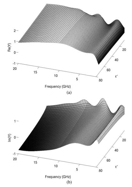
The parameters in (2) must be obtained for the coaxial dipole antenna used in this study. The analytical transmission line model was used to compute the aperture admittance of the dipole antenna in the frequency range of 400 MHz to 20 GHz, using relative permittivity values at 4 ≤ ≤ 80 (see Fig. 4). The parameters αnp and βmq in (2) were obtained through nonlinear fitting with the Levenberg–Marquardt algorithm provided in commercial software (Matlab R2009b, Mathworks, Natick, MA). The orders in (2) were P = Q = 4 and M = N = 8 which were determined based on tradeoff between fitting residual and stability for solving εr from (2). The coefficients calculated for use in (2) are listed in Table I.
Fig. 4.
Analytically computed real (a) and imaginary (b) components of aperture admittance of the coaxial dipole antenna normalized to the characteristic admittance (i.e., 0.02 S). Variations in admittance with respect to permittivity and frequency indicate that the dipole design will be sensitive to, and suitable for measurement of, the surrounding tissue properties.
TABLE I.
Fitted Coefficients of Rational Function Model: (a) αnp and (b) βmq.
| (a) | ||||
|---|---|---|---|---|
| p | 1 | 2 | 3 | 4 |
| n | ||||
| 1 | 1.066E+00 | 5.556E-01 | −8.229E-02 | 3.392E-03 |
| 2 | −1.361E+02 | 5.100E+01 | −2.288E+00 | 2.617E-01 |
| 3 | 2.887E+02 | −3.693E+02 | 8.681E+01 | −1.074E+00 |
| 4 | 2.464E+03 | −2.449E+03 | 5.950E+02 | −2.045E+01 |
| 5 | 1.291E+04 | −1.093E+04 | 2.353E+03 | −1.033E+02 |
| 6 | 1.680E+04 | −1.311E+04 | 2.826E+03 | −1.349E+02 |
| 7 | 2.708E+04 | −2.017E+04 | 3.825E+03 | −1.839E+02 |
| 8 | 6.370E+03 | −3.689E+03 | 6.167E+02 | −2.662E+01 |
| (b) | |||||
|---|---|---|---|---|---|
| q | 0 | 1 | 2 | 3 | 4 |
| m | |||||
| 1 | −1.031E+02 | 5.995E+01 | −1.128E+01 | 1.223E+00 | −3.863E-02 |
| 2 | −2.568E+02 | 6.455E+00 | 2.323E+01 | 8.145E-01 | 2.072E-01 |
| 3 | −4.620E+02 | −3.596E+02 | −5.878E+01 | 6.809E+01 | −1.479E+00 |
| 4 | 6.830E+03 | −3.777E+03 | −8.914E+02 | 4.783E+02 | −1.954E+01 |
| 5 | 2.352E+04 | −1.374E+04 | −1.734E+03 | 1.230E+03 | −6.243E+01 |
| 6 | 2.715E+04 | −1.902E+03 | −1.030E+04 | 2.794E+03 | −1.364E+02 |
| 7 | 3.501E+04 | −7.295E+03 | −9.544E+03 | 2.698E+03 | −1.432E+02 |
| 8 | −4.206E+03 | 2.311E+04 | −1.402E+04 | 2.436E+03 | −1.114E+02 |
= 1.0E-11 in (2).
The relative errors ∣ΔY/Y∣, where εY denotes the difference between the calculated and fitted admittance data, are plotted in Fig. 5. Relative errors were on the order of 10−3 for 14 ≤ ≤ 80 and 1.2 GHz ≤ f ≤ 18 GHz, which was considered acceptable for this work.
Fig. 5.
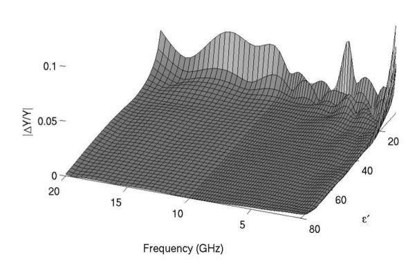
Error in aperture admittance for parametric fitting of rational function model. Errors were less than 2% for frequencies greater than 1 GHz and permittivities greater than 12. Since the antenna is intended to measure relative permittivities from 20 to 50 at frequencies of 2–3 GHz, these errors were considered acceptable.
E. Ex Vivo Validation Setup
The proposed dielectric measurement model was validated in ex vivo tissue experiments. Samples of bovine liver tissue (~500 g) were excised from stored whole livers and warmed to room temperature. Before applying microwave energy, calibration of the dipole antenna was conducted using three referencing liquids: deionized tap water, methanol (A412-1, Fisher Scientific, Hampton, NH), and ethanediol (E178-1, Fisher Scientific, Hampton, NH). The dielectric properties of these liquids have been well documented and their values are plotted in Fig. 6 [12], [13]. The S11 data of the dipole antenna in the referencing liquids were measured by using a vector network analyzer (E5071 C; Agilent Technologies, Palo Alto, CA) and, together with the values obtained from the analytical transmission line model, the calibration for each subsequent tissue measurement was established [14], [15].
Fig. 6.
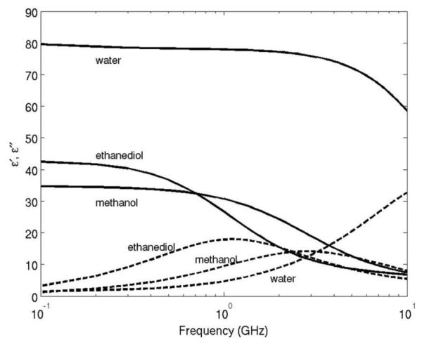
Dielectric dispersion curves of water, ethanediol, and methanol.
Next, dipole antennas were inserted at least 6 cm into the liver tissue sample. S11 was again measured in the range of 300 kHz to 20 GHz with a step size of 25 MHz. These measurements were used to calculate input admittance and, by using the rational function model developed previously, complex permittivity.
The validation measurements were carried out in both normal and ablated tissue samples. Ablations were carried out by using 30–45 W at 2.45 GHz for 2–5 min to create various ablation zone sizes. Since repetitive ablation procedures could degrade the prototype antennas and increase measurement errors, a separate identical antenna was used for most ablation procedures. After heating, the ablation antenna was retracted and replaced by the calibrated measurement antenna (see Fig. 7). In one case, the ablation antenna was left in place and used for dielectric property measurement to evaluate the feasibility of this approach in the future.
Fig. 7.
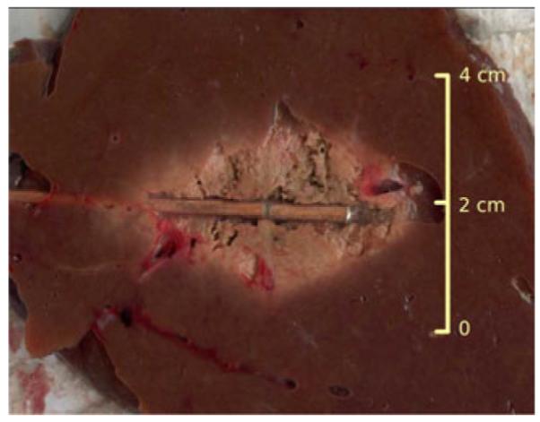
Picture of ablated tissue and the placement of the coaxial dipole antenna.
In each experiment, a companion open-ended coaxial measurement was performed on the surface of the sectioned ablation zone [8], [9]. In general, the dielectric properties were nonuniform across the zone of ablation, with lower permittivity and electrical conductivity near the center and values approaching those of normal liver at the rim. Therefore, open-ended coaxial probe measurements were taken near the center of the ablation, but avoiding any charred tissue.
F. Results Regularization
Measurement data from the dipole antenna presented later in Section III demonstrated some fluctuation at the lower frequency range. To account for errors or nonconsistency in the dipole antenna measurements, we fit the dipole data to a multipole Cole–Cole dispersion model [16]
| (4) |
where τ is a time constant to characterize the relaxation of dielectric polarization in a frequency range, ε∞ is the permittivity at field frequencies where ρτ >> 1, Δε is the magnitude of dispersion, α is a measure of the broadening of the dispersion, and σs is the static ionic conductivity.
In this study, (4) was used with three poles (n = 1, … , 3) and fit using least-squares nonlinear fitting in commercial software (MATLAB 2009b). Initial parameters for liver were chosen from [15]. ε∞ = 4 was fixed in the fitting while other parameters were bound to the domain {Δεn , τ n , αn , σs} ∈ (0, ∞).
III. Results
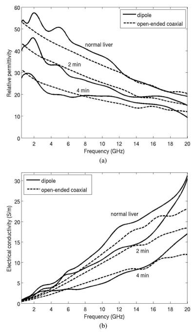
Three pairs of measured dielectric values from the antenna and open-ended coaxial cable are plotted in Fig. 8. Data collected using the open-ended coaxial probe and dipole antenna are in generally good agreement, and exhibit similar trends: decreasing relative permittivity and effective conductivity with increased time of ablation.
Fig. 8.
Measured dielectric data of bovine liver tissue by coaxial dipole antenna and open-ended coaxial cable. Measurements were performed in normal liver, and using 30 W for 2 min and 4 min. Longer heating times create greater tissue temperatures in the center of the ablation zone, resulting in greater changes in dielectric properties. (a) Relative permittivity an (b) electrical conductivity.
Sources of error between the open-ended coaxial probe and dipole antenna measurements are attributed to potential differences in the measurement volume of each probe, errors in calibration with each system, and fabrication errors that reduce agreement between theoretical and experimental geometries. In particular, the open-ended coaxial probe measures a small tissue volume (~2mm3), so it is more spatially accurate. The dipole effectively measures a weighted average of the adjacent tissue volume, so it is not as sensitive to spatial variations in tissue properties. Therefore, differences between open-ended coaxial probe and dipole antenna measurements may not necessarily indicate the accuracy of the dipole antenna measurements as much as differences in the volumes of tissue measured by each technique. The dipole structure is also more complex than the open-ended coaxial probe, increasing the likelihood for fabrication errors.
Fig. 9 shows the mean percentage difference between the open-ended coaxial probe and dipole antenna measurements. The data include ten experiments, including three performed in normal liver and seven performed in ablated liver. Ablation zone diameters ranged from 0.9 cm to 2.4 cm. The overall difference in permittivity measured between the two techniques was approximately 10% from 500 MHz to 20 GHz, indicating a relatively good agreement. The overall difference in conductivity was approximately 20% from 5 to 17 GHz, but considerably greater outside of this range.
Fig. 9.
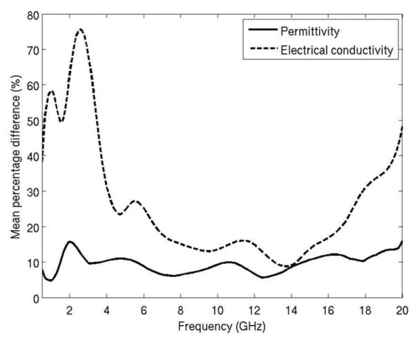
Mean percentage difference of dielectric measurement from a dipole antenna and open-ended coaxial cable.
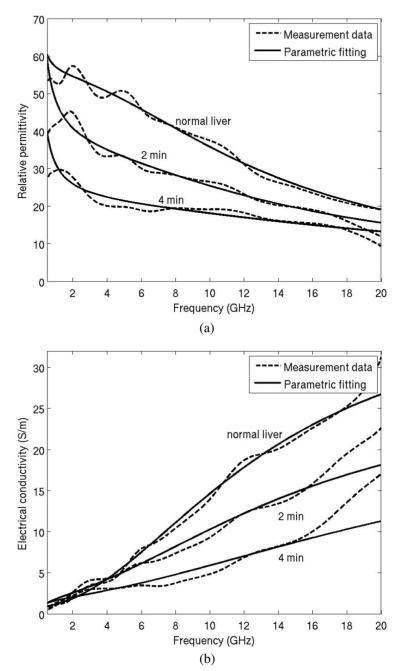
Much of the observed error and variability was effectively smoothed by fitting measured data to the Cole–Cole dispersion model of (4), (see Fig. 10). Initial and best-fit parameters for (4) are provided in Table II. The decrease of Δε1 with increased ablation was expected due to the loss of water in the ablated tissue. The trend of decreasing τ1 with greater ablation zone size may indicate an increase in unbound water and the decrease of σs indicated the decrease of iconic conduction caused by the heating process.
Fig. 10.
Parametric fitting of the measured dielectric data to the Cole–Cole model. Measurement data were from normal liver, and using 30 W for 2 min and 4 min. (a) Relative permittivity and (b) electrical conductivity.
TABLE II.
Initial and Fitted Parameters for the Cole-Cole Dispersion Model
| Initial [16] | Fresh bovine liver |
30 W 2 min ablation |
30 W 4 min ablation |
|
|---|---|---|---|---|
| Δ ε 1 | 39 | 49.6 | 24.9 | 14.5 |
| Δ ε 2 | 6.0×10³ | 5.0×10³ | 4.1×10³ | 7.0×10³ |
| Δ ε 3 | 5.0×10⁴ | 5.5×10⁴ | 2.8×10⁴ | 3.7×10⁴ |
| τ1[ps] | 8.84 | 12.17 | 10.78 | 7.21 |
| τ2[ns] | 530.52 | 180.37 | 292.13 | 449.97 |
| τ3[μs] | 22.74 | 46.65 | 14.99 | 6.32 |
| α 1 | 0.1 | 0 | 0.33 | 0 |
| α 2 | 0.2 | 0.14 | 0.36 | 0.25 |
| α 1 | 0.2 | 0.14 | 0.35 | 0.25 |
| σ s | 0.02 | 0.0091 | 0.0025 | 0.0012 |
ε∞ = 4.0 (fixed).
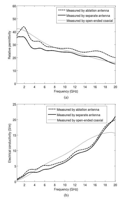
Finally, a comparison of data collected using a separate antenna versus the ablation antenna for dielectric measurement is found in Fig. 11. Both measurement curves lie in the similar proximity of the open-ended coaxial measurement with about 10% difference with each other.
Fig. 11.
Comparison between dielectric measurement with the ablation antenna and a spare measurement antenna. (a) Relative permittivity and (b) electrical conductivity.
IV. Discussions
The relatively good agreement between open-ended coaxial and dipole measurements suggests that it is feasible to track dielectric changes during microwave ablation using the interstitial heating antenna. This technique was able to identify changes in dielectric properties and Cole–Cole parameters, which are known to correlate with thermal ablations. Observing such changes in real time during microwave ablation may provide a feedback mechanism to regulate the power or frequency of the generator to produce optimal energy deposition, and as a tool to assess the progress of the thermal ablation.
In a previous study [3], we proposed a method to estimate the tumor boundary through time-domain analysis of pulse reflection which requires a wide-band S11 measurement. We estimate that, with modification, this method could be used for ablation zone monitoring with the assumption that the dielectric boundary exists between treated and untreated tissue. We have demonstrated here that relative permittivity can be measured fairly accurately using a dipole antenna over a broad frequency range. Therefore, the wave propagation speed inside the ablation zone can be estimated to improve the accuracy of the method proposed in [3]. We also note that since the wave velocity is proportional to the inverse of , errors in relative permittivity estimation will result in relatively small errors in wave velocity estimation.
Based on the analysis of the electric field pattern produced by the dipole antenna in liver, the sensing region was about 1 cm in diameter around the axis of the antenna. This volume is much larger than 2–3 mm estimated for an open-ended coaxial cable, but is smaller than the ablation zone in most microwave ablations. In addition, because of the lossy nature of tissue, greater weight is given to the tissue nearest to the antenna.
Compared with the open-ended coaxial probe, dipole antenna measurements exhibited variations or “ripples” at the lower frequency range, especially in the effective conductivity measurement (see Fig. 8). This may be related to inhomogeneous permittivity in the ablation zone, which causes distortion in the reflection coefficients from the antenna. It may also be due to the fact that the sensitivity of the reflection coefficients with respect to the dielectric change is fairly low at part of the frequency range, as shown in Fig. 3. However this measurement fluctuation can be effectively smoothed by fitting to a Cole–Cole dispersion model. Nevertheless, relative permittivity measurements with the dipole antenna were in good agreement with the open-ended coaxial probe, making such measurements feasible for tissue characterization in other applications.
There were some errors between measurements performed using a separate antenna and those performed using the ablation antenna. These errors were relatively small, demonstrating the feasibility of using a single applicator for heating and measurement. Since in general the sensitivity of the antenna is low, the errors can be caused by differences in antenna fabrication and the positioning when conducting the measurements. The thermal expansion in the ablation antenna would reduce the validity of the calibration procedure performed prior to the ablation. Precision and thermally stable antenna fabrication may reduce the likelihood of these errors.
V. Conclusion
A method to measure the dielectric properties of tissue using a dipole microwave ablation antenna was developed. This method has the possible advantage over open-ended coaxial probes in that the measurement can be carried out during an ablation procedure without interruption of the treatment or insertion of additional devices. We estimate that an improved antenna design with optimal tradeoff between dielectric sensitivity and ablation performance can provide more robust dielectric measurements. Measurement accuracy may also be achieved with more precise antenna construction and more thermally stable materials.
Acknowledgments
This work was supported by the National Institute of Health (NIH) under Grant R01 CA142737.
Biography

Peng Wang received the B.S. degree in electrical engineering from Tsinghua University, Beijing, China, in 1998, and the M.Eng. degree in electrical and electronic engineering from Nanyang Technological University, Singapore, in 2002. He also received the M.S. and Ph.D. degrees in biomedical engineering from the University of Wisconsin–Madison, Madison, in 2007 and 2009, respectively.
He is currently a Research Associate in the Department of Medical Physics, University of Wisconsin–Madison. His research interests include microwave thermal ablation and interventional magnetic resonance imaging.
Dr. Wang is a member of the International Society for Magnetic Resonance in Medicine.
Christopher L. Brace (S’01–M’05) received the B.S. degree in physics and B.S.E.E from the University of Wisconsin–Milwaukee, Milwaukee, in 2001, and the M.S.E.E. and Ph.D. degrees from the University of Wisconsin–Madison, Madison, in 2003 and 2005, respectively.
He has been an Assistant Scientist and is currently an Assistant Professor in the Departments of Radiology and Biomedical Engineering, University of Wisconsin–Madison. His research interests include image-guided interventional oncology, thermal therapies such as radiofrequency and microwave ablation, medical imaging, and applications of electromagnetics in medicine.
Dr. Brace is a member of the IEEE Engineering in Medicine and Biology Society, Society for Thermal Medicine, and Biomedical Engineering Society.
Contributor Information
Peng Wang, Department of Medical Physics, University of Wisconsin-Madison, Madison, WI 53705 USA.
Christopher L. Brace, Department of Radiology, University of Wisconsin-Madison, Madison, WI 53705 USA (clbrace@wisc.edu).
References
- [1].Lin JC, Wang Y-L, Hariman RJ. Comparison of power deposition patterns produced by microwave and radio frequency cardiac ablation catheters. Electron. Lett. 1994;vol. 30(no. 12):922–923. [Google Scholar]
- [2].Antoch G, Kuehl H, Vogt FM, Debatin JF, Stattaus J. Value of CT volume imaging for optimal placement of radiofrequency ablation probes in liver lesions. J. Vasc. Interv. Radiol. 2002 Nov.vol. 13(no. 11):1155–1161. doi: 10.1016/s1051-0443(07)61958-7. [DOI] [PubMed] [Google Scholar]
- [3].Wang P, Brace CL, Converse MC, Webster JG. Tumor boundary estimation through time-domain peaks monitoring: numerical predictions and experimental results in tissue-mimicking phantoms. IEEE Trans. Biomed. Eng. 2009 Nov.vol. 56(no. 11):2634–2641. doi: 10.1109/TBME.2009.2025963. [DOI] [PMC free article] [PubMed] [Google Scholar]
- [4].Brace CL. Temperature-dependent dielectric properties of liver tissue measured during thermal ablation: Toward an improved numerical model. Proc. Annu. Int. Conf. IEEE Eng. Med. Biol. Soc. 2008 Aug.:230–233. doi: 10.1109/IEMBS.2008.4649132. [DOI] [PubMed] [Google Scholar]
- [5].Ji Z, Brace CL. Expanded modeling of temperature-dependent dielectric properties for microwave thermal ablation. Phys. Med. Biol. 2011 Aug.vol. 56(no. 16):5249–5264. doi: 10.1088/0031-9155/56/16/011. [DOI] [PMC free article] [PubMed] [Google Scholar]
- [6].Stuchly MA, Kraszewski A, Stuchly SS, Smith AM. Dielectric properties of animal tissues in vivo at radio and microwave frequencies: Comparison between species. Phys. Med. Biol. 1982 Jul.vol. 27(no. 7):927–936. doi: 10.1088/0031-9155/27/7/004. [DOI] [PubMed] [Google Scholar]
- [7].Bertram JM, Yang D, Converse MC, Webster JG, Mahvi DM. A review of coaxial-based interstitial antennas for hepatic microwave ablation. Crit. Rev. Biomed. Eng. 2006;vol. 34(no. 3):187–213. doi: 10.1615/critrevbiomedeng.v34.i3.10. [DOI] [PubMed] [Google Scholar]
- [8].Stuchly SS, Sibbald CL, Anderson JM. A new aperture admittance model for open-ended waveguides. IEEE Trans. Microw. Theory Tech. 1994 Feb.vol. 42(no. 2):192–198. [Google Scholar]
- [9].Anderson JM, Sibbald CL, Stuchly SS. Dielectric measurements using a rational function model. IEEE Trans. Microw. Theory Tech. 1994 Feb.vol. 42(no. 2):199–204. [Google Scholar]
- [10].Wang P, Converse MC, Webster JG, Mahvi DM. ‘Improved’ calculation of reflection coefficient for coaxial antennas with feed gap effect. IEEE Trans. Antennas Propag. 2009 Feb.vol. 57(no. 2):559–563. [Google Scholar]
- [11].Guillemin EA. Synthesis of Passive Networks: Theory and Methods Appropriate to the Realization and Approximation Problems. Wiley; New York: 1957. [Google Scholar]
- [12].Buchner R, Barthel J, Stauber J. The dielectric relaxation of water between 0 °C and 35 °C. Chem. Phys. Lett. 1999 Jun.vol. 306(no. 1–2):57–63. [Google Scholar]
- [13].Jordan BP, Sheppard RJ, Szwarnowski S. The dielectric properties of formamide, ethanediol and methanol. J. Phys. D, Appl. Phys. 1978 Apr.vol. 11(no. 5):695–701. [Google Scholar]
- [14].da Silva EF, McPhun MK. Calibration techniques for one port measurement. Microw. J. 1978 Jun.vol. 21(no. 6):97–100. [Google Scholar]
- [15].Kraszewski A, Stuchly MA, Stuchly SS. ANA calibration method for measurements of dielectric properties. IEEE Trans. Instrum. Meas. 1983 Jun.vol. 32(no. 2):385–387. [Google Scholar]
- [16].Gabriel S, Lau RW, Gabriel C. The dielectric properties of biological tissues: III. Parametric models for the dielectric spectrum of tissues. Phys. Med. Biol. 1996;vol. 41:2271–2293. doi: 10.1088/0031-9155/41/11/003. [DOI] [PubMed] [Google Scholar]


