Abstract
Digital Imaging and Communications in Medicine (DICOM) has brought a very high level of standardization to medical images, allowing interoperability in many cases. However, there are still challenges facing the informaticist attempting to data mine DICOM objects. Images (and other objects) from different vintage equipment will encompass different levels of the standard, and there are also proprietary “shadow” tags to be aware of. The database architecture described herein “flattens” such differences by compiling a knowledge base of specific DICOM implementations and mapping variable data elements to a common lexicon for subsequent queries. The project is open sourced, built on open infrastructure, and is available at GitHub.
Keywords: Data mining, Databases, Computer systems
Background
Digital Imaging and Communications in Medicine (DICOM) has brought a very high level of standardization to medical images, allowing interoperability in many cases. However, there are still challenges facing the informaticist attempting to data mine DICOM object headers (as opposed to the actual image itself). Images from different vintage equipment will encompass different levels of the standard. For example, consider the example radiography and attempting to get information related to patient exposure. In the early days of Fuji CR, a value referred to as the “S-number” could be massaged to yield an approximation of the patient's radiation exposure (Fuji Medical Systems, Stamford, CT). As technology progressed, other vendors have linked radiation information to Modality Performed Procedure Step (MPPS) or DICOM Dose Structured Report (SR) messages. These examples all use the DICOM standard, but based on the year of manufacture, each device may implement the same information in different “standard” ways.
The situation is further complicated by the fact the some vendors may link information such as tube voltage, tube current, and source to skin distance in custom “shadow” DICOM tags. The DICOM standard defines even numbered groups to house publicly known standard elements while odd-numbered group tags are reserved for custom vendor use. There is no requirement among vendors to share how to decode such custom elements.
The situation is not merely limited to radiation-related information. In even the simple case of defining the start time of a magnetic resonance (MR) series, the series time stamp may not indicate the actual onset of image acquisition—it may simply indicate the time the scan protocol for that series was selected. In one case, the actual onset of image acquisition was indicated by a shadow tag related to the activation of the MR magnetic field gradient. In another MR example, it turns out that the pulse sequence were not in a standard location until the recently approved enhanced MR objects [1]. Hence, locating something as basic as the MR pulse sequence is a vendor-dependant search among shadow groups on older scanners.
The preceding examples show that there are two challenges to be faced: the ambiguity of what an item means (even if it's in a standard location), and the location of a data element if it is not in a standard location (or the standard has yet to define one). There have been several attempts to address these challenges. In the particular case of radiation monitoring, there are several efforts. The Integrating the Healthcare Enterprise (IHE) consortium has recently initiated the IHE-Radiation Exposure Monitoring (REM) profile [2]. However, that effort requires the vendor to have implemented the DICOM Dose SR object, a feature that is only available on the very newest modalities. Another group has addressed the issue for the specific case of pre-DICOM Dose SR computed tomography (CT) scanners by using optical character recognition to harvest data from the exam's screen shot of the protocol's radiation information [3].
While these approaches have succeeded in their respective niches, there has not been to date an approach that enables harvesting arbitrary data elements (not just dose information), across the epochs of DICOM implementations, and mapping such data to a standard lexicon enabling simplified database queries using standard Structured Query Language (SQL) in a relational database. In fact, it has been suggested that the problem is so intractable it can only be solved by so-called “No-SQL” approaches that are used to index variable data by such corporations as Google (Google Incorporated, Mountain View, CA) and Amazon (Amazon Corporation, Seattle, WA) [4, 5].
The method followed in this work has avoided no-SQL approaches, yet scales and adapts as needed to index arbitrary data of interest from the universe of DICOM imagers. It does this by creating a knowledge base that indexes every make, model, and software version of modalities that it “sees” and builds a custom dictionary for that device that maps its data tags to standard names defined by the user. Subsequently, SQL queries can be executed on those standard names and harvest the mapped data regardless of where it was actually stored in the original DICOM header. Earlier work attempted a similar approach, but suffered from some limitations; the software used included a non-free database (Oracle Corporation Redwood Shores, CA) and presentation layer (Microsoft .NET, Microsoft Corporation Redmond, WA), hence the result could not be open sourced in a tangible sense. Furthermore, the knowledge base architecture was not completely developed [6, 7]. Because of this, when DOSE SR objects came along, new tables where added on a per vendor ad hoc basis to support new custom queries. The DICOM Data Warehouse (DDW) avoids these issues by fully exploiting strategies from an earlier work [8].
Methods
The DDW architecture was carefully considered to enable a freely available, yet industry friendly, open source project. As such, not only its code, but the underlying technologies are freely redistributable. The entry point to the system is MIRTH Connect V 2.0 (Mirth Corporation, Irvine CA). This is the gateway for DICOM images to enter the system. A MIRTH DICOM channel performs the work of data harvesting and mapping the data to the database, and then throws away the image. The database is PostgreSQL V9.0 (PostgreSQL http://postgresql.org). Any user who desires to obtain and run the system need only:
Obtain and install MIRTH Connect on their operating system of choice;
Obtain and install PostgreSQL on their operating system of choice;
Obtain and install the DDW MIRTH channel and database. These items and instructions for their installation are at Github (http://github.com/sglanger/ddw).
Point DICOM modalities at the MIRTH gateway and begin acquiring data (which may require setting up the device in the knowledge base if it has not been encountered before).
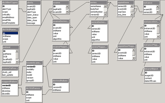
Before delving further into the mechanics of the DDW, it is beneficial to understand the overall database design. In programming multi-tiered applications, it is considered best practice to isolate the data model from operations on, and views of, the data. This paradigm, referred to as MVC (Model View Controller) has analogs in the design of DDW [9]. The data model (also referred to as the schema) is shown in Fig. 1.
Fig. 1.
The DDW (DICOM Data Warehouse) database architecture. For a detailed explanation consult the text
Model
The schema has the following components and features:
Patient/exam/series/acquisition/instance tables collect generic values that are standard across all modalities and implementations. Notice that the last four tables have a column of related tables below them. These are to store either mapped or derived values that are within the scope of their parent table.
- Knowledge base: Lower left four tables
- This ring of four tables indexes each known modality (knownScanners) and assigns modality specific or custom values in the header to the table mappedValues, or creates place holders for calculated results in the derivedValues table. Both Values tables link that data element to its scope (i.e. series level, instance level, etc.) and a user defined standard name.
- User defined names are in the table dictStdNames. It contains items like instance_KVP, or instance_Exposure. For some equipment, instance_Exposure may be in a private tag and would go into mappedValues. For other devices (like Fuji CR) the exposure may have to be derived from more basic information, that result is stored in derivedValues.
- As previously mentioned, the four columns of tables under exams/series/acquisition/instance are the containers for the data elements that fall within that scope. The run-time assignment to these tables occurs in the following manner:
- As MIRTH accepts a DICOM association, it checks the knowledge base to find if this scanner version is known
- Assuming there is a match, the MIRTH DDW channel then reads the mapping instructions from the knowledge base and begins assigning DICOM header elements to the database based on those instructions. For example, a custom radiation exposure tag at the series level would be mapped to seriesMappedValues under the name “series_Exposure”.
- Exceptions to the above
- One notes under the instance column that there is an additional table “binaryObject”. If ARCHIVE = true in the DICOM channel, the entire DICOM header is stored. If desired, actual images (such as the dose screen in CT) may also be captured and stored (for example to be later processed by optical character recognition software).
- The remaining tables
- dictAlertTypes classifies all the error conditions the system knows about such as: unknown scanner, missing required header information, etc.
- dictStdNames is the table created by the user as they add standard terms against which they will later map the DICOM tags to
- “alerts” list the current pending errors that require action
- examsToProcess lists what studies have been received and the last time an image was received for that study. A dispatcher process looks at this table every minute and after a configurable delay from the last update, initiates the processing algorithms to calculate items in the derivedValues tables.
Upon reflection it is clear any header element prospectively defined can be specifically indexed in tables and reported on using SQL queries leveraging terms in the table dictStdNames. If specific elements were not considered ahead of time, but ARCHIVE was set to “true”, one can perform ad hoc queries on the per instance binaryObject header dump to perform retrospective analytics.
Controller
The preceding describes the DDW data model. The controller aspect can be addressed in several ways. Recall the controller is the agent(s) that performs operations on the data. The simplest way to write DDW controllers is as stored procedures within the DDW database. Recall a dispatcher process assigns work to algorithms based on pending entries in the examsToProcess table. Just as the MIRTH channel uses the knowledge base to determine data mapping when an image is received, an algorithm uses the knowledge base to determine what data should be its functional inputs, and where to write its output among the derivedValues tables. Once the algorithm returns control to the dispatcher, it deletes the StudyUID entry from the examsToProcess table. It is also possible to write controllers outside the database in arbitrary languages, and communicate with the DDW database via the JDBC (Java Database Connectivity) protocol. It would be important though to avoid having both internal and external algorithms that address the same classes of scanner versions.
View
At this time, there is no view functionality (aka graphical user interface) in DDW except in the trivial sense that a user can execute SQL queries on the tables and see a set of rows returned or the result of simple calculations.
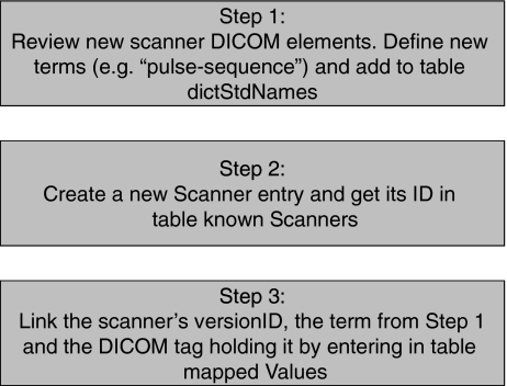
The process of registering an unknown scanner software version in DDW follows the following workflow (Fig. 2):
The user reviews the DICOM header of the new modality, and determines if additional terms are needed in dictStdNames to accommodate that scanner.
The user adds the new scanner make/model/version information to the table knownScanners. When the entry is complete the database returns a new ID number for that particular scanner. It is also at this time the user assigns a group ID to the scanner version. The purpose of the group ID is to map a single analytic algorithm to all scanner versions that are essentially similar in their headers, even if they are different software versions.
Finally, the user populates the mappedValues and derivedValues tables. In the case of the former, the user also stipulates what DICOM tag holds the item of interest. In both cases (mapped or derived), the user defines what standard name will be bound to the item. This enables the database to perform a “view” that links a version to all data elements of interest, where they will be found, and how they will be named in subsequent SQL queries.
Fig. 2.
The process of registering a new scanner version in DDW
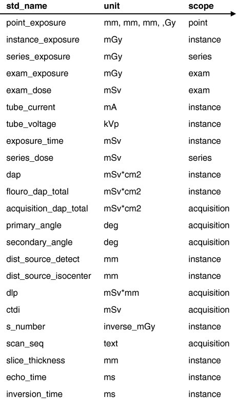
To clarify the preceding, consider the following example of defined terms (Fig. 3):
Fig. 3.
An example of the standard names known by this DDW instance
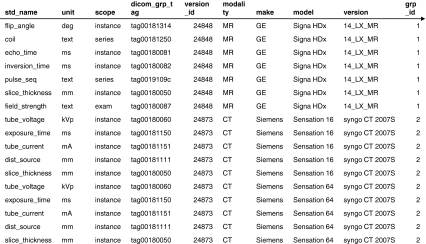
The table consists of a unique name, its unit, and its scope of applicability. This information provides the listing of possible terms that can be applied to any given scanner. What is actually defined for a scanner is computed by joining scanner information to the mappedValues and derivedValues tables. To understand how the mappedValue table in the DDW knowledge base is used by the MIRTH channel to map modality specific or custom tags, the following figure is helpful (Fig. 4).
Fig. 4.
A view into the DDW database that shows the additional tags of interest that the system will harvest and index for three modalities: a GE MR, a Siemens Sensation 16 CT and Sensation 64 CT
Note that this table sorts all the tags of interest for a specific modality version in a continuous row set. This permits the MIRTH channel to look at this table and find all the tags that the user predefined for indexing for that imager. For example, if MIRTH is ingesting a GE MR image at the moment, it would find that the MR field strength is in the DICOM tag (0018, 0087) and that it should write the value of that tag to the examMappedValues table. In an exactly similar manner, algorithms computing derived objects use the derivedValue table to assign values they compute to the proper table (exams, series, acquisition, or instance derivedValues).
When the DDW dispatcher detects an exam to process, it uses the indicated Study UID to open the matching series entries in the Series table. There it finds the group ID (the same one shown in Fig. 3) that is a reference to the proper algorithm to invoke. To continue the previous MR example, the dispatcher would invoke algorithm 1 to compute derived values of interest for the GE Signa HDx.
Results and Discussion
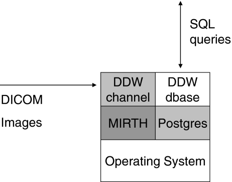
The constituents of the DDW have been deployed in several ways. In the development environment, the entire application is deployed on a single personal computer (Fig. 5).
Fig. 5.
The system level architecture of DDW implemented on a single personal computer for development purposes
In this model, the images come to the MIRTH DICOM channel; the tags are harvested and written to the database. However, in a production environment, it may be desirable to deploy multiple MIRTH gateways across the enterprise for several reasons (Fig. 6):
Recall that MIRTH throws away the image after parsing, so keeping MIRTH near the point of image creation means only SQL data needs to be transferred long distances over computer networks, reducing network demands [10].
Even in a single location, a large medical center may overwhelm a single gateway. A cluster of them can be deployed behind a load balancing switch for load balancing.
Fig. 6.
System level architecture of DDW for a production level deployment among multiple locations. In one site, a single MIRTH gateway is sufficient for the local image generation. In another site, the image volume requires a cluster of MIRTH nodes behind a load balancing switch. After data harvesting, all MIRTH gateways communicate their results to the central database via JDBC (Java Database Connectivity) links
In either case, all data is collected to a single database instance, enabling a single point of query for enterprise dashboards.
At this point, the DDW does not include a graphical user interface with premade reports. It would be relatively straightforward, however, to implement a Web-based interface to accomplish that task using open tools such as Ruby on Rails [11]. Ideally, such an interface should implement the following functions:
enable the user to see system alerts and respond to them;
enable the user to input the data alluded to in points 1–3 above;
enable running previously prepared static reports;
enable ad hoc reports via user entered elements in a manner similar article searches in PubMed [12].
As for performance, the DDW on a development machine running Microsoft Windows XP (32 bit) with one 2-GHz processor and 3 GB of memory has been shown to ingest two CT images/second. To put this in perspective, two different PACS implementations at our site can ingest three and four CT images/second on their DICOM input gateways, respectively. Preliminary work shows that about 75% of the time per image is on the MIRTH gateway (presumably while the image is being parsed). Therefore, the load balanced cluster approach seen in Fig. 5 would appear to be an obvious strategy to scale performance.
Currently the system “knows”: three MR configurations, three CT versions, three CR, two DR, one RF, and two mammographic scanners. The ability to dump reports to our MR research group that shows what exams have had which research pulse sequence (stored in vendor specific shadow groups) has already proven useful. To date, only a few proofs of concept analytics have been written, largely to illustrate the system's run-time behavior to interested developers.
Conclusions
The abstraction of varied vendor data to a common lexicon enables the creation of simple SQL based algorithms, either within or external to a database, to perform data mining analytics on DICOM instances regardless of the DICOM implementation's vintage. The described system is barely 3 months old, yet it already incorporates some advanced features such as tagging results in the derivedValues tables with the specific algorithm and version used to enable recovery if an error becomes known and it becomes necessary to assess what exam results are compromised.
While some may stumble at the current lack of a mature Web user interface, it is important to realize that this is simply icing on the cake. The current database architecture enables any Web savvy programmer to build query forms, and populate them, with little to no experience in DICOM. Furthermore, such query logic can be made static since the terms comprising the queries are in fixed tables and views. Only the items in those table columns change. By achieving this, the DDW pushes the need for DICOM expertise from the generic programmer to the informaticist or medical physicist who (one assumes) are the domain experts on such new equipment.
Our hope in releasing this framework as an open source project on Github is that others will pull down the code base and use it at their institutions. Users can contribute to the knowledge base by posting their local site's scanner information back to GitHub, or sending it to the author for inclusion in subsequent releases. The community, as always, is welcome to comment on any discrepancies.
Footnotes
For development purposes, data used in this work was obtained from quality control phantom scans; no patient identifiable data was used.
References
- 1.Enhanced MR Objects. ftp://medical.nema.org/medical/dicom/2009/09_03pu3.pdf Section C.8.13. Accessed August 2011
- 2.IHE Radiation Exposure Monitoring profile. http://www.ihe.net/Technical_Framework/upload/IHE-RAD_TF_Suppl_Radiation-Exposure-Monitoring_TI_2008-07-03.pdf. Accessed June 2011
- 3.Cook TS: http://www.pennradiology.com/radiance/UsingRADIANCE.pdf. Accessed June 2011
- 4.Ekanayake J, Gunarathne T, Qiu J: Cloud technologies for bioinformatics applications. IEEE Transactions on Parallel and Distributed Systems 22(6):998–1011, 2011 doi:10.1109/TPDS.2010.178
- 5.Hadoop WT. The definitive guide 2nd edition. Sebastopol: O'Reilly Media; 2010. [Google Scholar]
- 6.Hu M, Pavlicek W, Liu PT, Zhang M, Langer SG, Wang S, Place V, Miranda R, Wu TT. Informatics in radiology: Efficiency metrics for imaging device productivity. Radiographics. 2011;31(2):603–616. doi: 10.1148/rg.312105714. [DOI] [PubMed] [Google Scholar]
- 7.*Wang S, Pavlicek W, Roberts CC, Langer SG, Zhang M, Hu M, Morin RL, Schueler BA, Wellnitz CV, Wu T: An automated DICOM database capable of arbitrary data mining (including radiation dose indicators) for quality monitoring. J Digit Imaging 24(2):223–33, 2011. PMID:20824303. doi:10.1007/s10278-010-9329-y. [DOI] [PMC free article] [PubMed]
- 8.Langer SG. Challenges for data storage in medical imaging research. J Digit Imaging. 2011;24(2):203–207. doi: 10.1007/s10278-010-9311-8. [DOI] [PMC free article] [PubMed] [Google Scholar]
- 9.Governor J, Nickel D, Hintchcliffe D. Web 2.0 architectures: Chapter 5. Sebastopol: O'Reilly Media; 2009. [Google Scholar]
- 10.Langer SG, French T, Segovis C. TCP/IP optimization over wide area networks: Implications for teleradiology. J Digit Imaging. 2011;24(2):314–321. doi: 10.1007/s10278-010-9309-2. [DOI] [PMC free article] [PubMed] [Google Scholar]
- 11.Thomas D, Hansson DH. Agile Web development with rails. Raleigh: Pragmatic Programmers; 2005. [Google Scholar]
- 12.Alexander G, Hauser S, Steely K, Ford G, Demner-Fushman D. A usability study of the PubMed on Tap user interface for PDAs. Stud Health Technol Inform. 2004;107(Pt 2):1411–1415. [PubMed] [Google Scholar]


