

Abstract
Red blood cells are frequently deformed and their cytoskeletal proteins such as spectrin and ankyrin-R are repeatedly subjected to mechanical forces. While the mechanics of spectrin was thoroughly investigated in vitro and in vivo, little is known about the mechanical behavior of ankyrin-R. In this study, we combine coarse-grained steered molecular dynamics simulations and atomic force spectroscopy to examine the mechanical response of ankyrin repeats (ARs) in a model synthetic AR protein NI6C, and in the D34 fragment of native ankyrin-R when these proteins are subjected to various stretching geometry conditions. Our steered molecular dynamics results, supported by AFM measurements, reveal an unusual mechanical anisotropy of ARs: their mechanical stability is greater when their unfolding is forced to propagate from the N-terminus toward the C-terminus (repeats unfold at ∼60 pN), as compared to the unfolding in the opposite direction (unfolding force ∼ 30 pN). This anisotropy is also reflected in the complex refolding behavior of ARs. The origin of this unfolding and refolding anisotropy is in the various numbers of native contacts that are broken and formed at the interfaces between neighboring repeats depending on the unfolding/refolding propagation directions. Finally, we discuss how these complex mechanical properties of ARs in D34 may affect its behavior in vivo.
Introduction
Red blood cells (RBCs) undergo repeated stress and deformation cycles while flowing through the capillaries and narrow slits of the spleen (1,2). This process subjects the membrane and associated cytoskeletal proteins to mechanical forces. Spectrin and ankyrin-R are among the key components of the erythrocyte membrane cytoskeleton network (3). Their elastic properties are vital for RBC mechanical integrity and their structural recovery from deformations. The mechanical properties of spectrin have been investigated in vitro through AFM-based single-molecule force spectroscopy and molecular dynamics simulations (4–8), and in vivo where force-induced spectrin unfolding in live RBCs under physiological stress was captured (9,10).
The primary function of ankyrin-R in human erythrocytes is to link the anion exchanger to the spectrin/actin network (3,11). The membrane-binding domain of ankyrin-R is composed of 24 ankyrin repeats (ARs) that provide a binding surface for several proteins. Like spectrin repeats, ARs are also composed of α-helices, but their assembly into a tertiary structure is very different from that of spectrin. Generally, ARs, which are composed of 33 residues that form two antiparallel α-helices (H1 and H2) and a loop, stack side by side to form elongated superhelical springlike structures that mediate protein-protein interactions. In contrast to spectrin, little is known about the mechanical properties of ankyrin-R, although it is expected that ankyrin-R is subjected to significant mechanical forces in vivo. Recently, Krieger et al. (10) observed ARs force-induced unfolding at relatively high shear forces. Earlier, by using extensive computer simulations, Sotomayor et al. (12) predicted that ankyrin-R would respond to stretching forces in two phases. At low forces, the curvature of the protein is expected to gradually decrease (tertiary structure elasticity), extending ankyrin-R reversibly similar to a Hookean spring. At larger forces, the simulations predicted the unfolding of individual repeats and rupture of the stack. A similar behavior was later observed experimentally for ankyrin-B (13). Interestingly, unlike most globular proteins studied so far that unfold in an all-or-none fashion, AR domains from a number of proteins have been demonstrated to unfold sequentially, repeat-by-repeat (13–17). ARs were also captured to refold rapidly, generating very robust refolding forces (13–16).
In vivo, ankyrin-R may be subjected to forces acting on different parts of the protein in various directions (Fig. 1 A). Its mechanical behavior and unfolding pathways may depend, in a relatively complicated manner, on details of the pulling geometry, as indicated by recent mechanical studies of other proteins (18–21). In this work, we use a combination of steered molecular dynamics (SMD) simulations (12,22–34) and atomic force microscopy (AFM)-based single-molecule force spectroscopy (35–42), to examine the mechanical properties of ankyrin repeat proteins, under different pulling geometry conditions.
Figure 1.
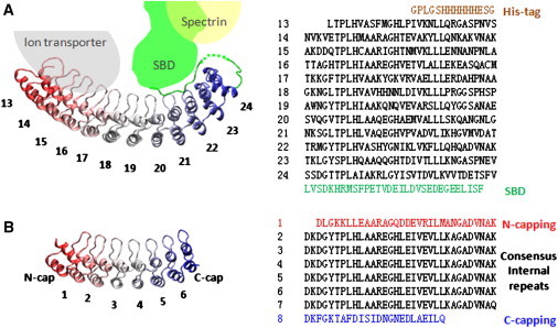
Ribbon diagrams and amino-acid sequences of D34 and NI6C. (A) The ribbon diagram of the D34 fragment of the membrane-binding domain of ankyrin-R (R13-R24, PDB 1N11 (11)). The beginning fragment of spectrin-binding domain (SBD) interacts with repeats R20–R24. Several ARs of ankyrin-R interact with the cytoplasmic domain of ion transporter, and SBD interacts with spectrin. The amino-acid sequence is shown in the right panel. (B) The ribbon diagram of NI6C. NI6C is composed of the N-capping repeat, the C-capping repeat, and six internal consensus repeats. (Right panel) The amino-acid sequence.
We first examine a model consensus AR protein, NI6C (Fig. 1 B), which displayed very robust mechanical unfolding and refolding behavior when stretched fully by its termini (14), and later the mechanics of D34, the C-terminal portion of the membrane binding domain of ankyrin-R. We chose this fragment of ankyrin-R because it is the longest fragment crystallized so far (11), and it is the center of intermolecular interactions with other components of the RBC membrane skeleton (Fig. 1 A). Moreover, the unfolding of D34 has been characterized in bulk denaturation studies (43,44), and its elastic behavior and partial unfolding has been characterized by all-atom SMD simulations (12).
Results and Discussion
Structure of NI6C and D34
NI6C is composed of two capping repeats and six identical consensus internal repeats (see Fig. 1 B, and Lee et al. (14) and Wetzel et al. (45)). The amino-acid sequence of consensus ARs in NI6C is derived from various native ARs; therefore, NI6C is a good model of an ankyrin repeat system. The D34 protein is composed of 12 ARs (R13–R24) that form a characteristic extended spiral domain. In the crystallized protein, D34 is followed by a 30 amino-acid fragment of the spectrin-binding domain (SBD) (PDB 1N11 (11)). This fragment (see green line in Fig. 3 A, inset) which has not been considered in previous computer simulations, folds back on repeats R20–R24, engaging with them through a set of hydrogen bonds. Fig. 1 A also shows a schematic diagram of D34 interactions with an ion-transporter and spectrin. We speculate that during blood circulation, D34 binding partners exert mechanical forces on various parts of D34 and may stretch ARs in different directions.
Figure 3.
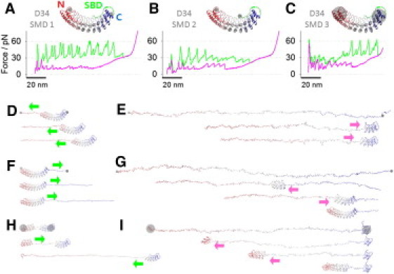
CG-SMD simulations of D34 unfolding and refolding. (A, inset) The pulling geometry of D34-SMD1. N-terminal residue, Leu403 of R13, and Glu792 of the last ANK repeat, R24 (gray dots), were subjected to stretching forces. The simulated unfolding force-extension trace (green) shows 50∼60 pN force peaks; the refolding trace (pink) shows mainly small refolding force peaks of ∼13 pN. (B, inset) The pulling geometry of D34-SMD2. Stretching forces were applied to two terminal residues (gray dots). The simulated unfolding force-extension trace (green) shows 30∼45 pN force peaks; the refolding trace (pink) shows ∼13 pN and ∼20 pN refolding force peaks. (C, inset) The pulling geometry of D34-SMD3. The COM of terminal repeats, R13-R14 and R23-R24 (gray circles), were stretched. The simulated unfolding (green) and refolding (pink) traces are shown. (D) Unfolding trajectory snapshots of D34-SMD1. Repeats were peeled off sequentially, from R13 to R24 (direction I). (E) Refolding trajectory snapshots of D34-rSMD1. R23-R24 nucleated first, then repeats refolded sequentially from R22 to R13 (direction III). (F) Unfolding trajectory snapshots of D34-SMD2. Repeats were peeled off sequentially from R24 to R13 (direction II). (G) Refolding trajectory snapshots of D34-rSMD2. The middle four repeats, R17–R20, nucleated first. Then the D4 fragment refolded sequentially from R21 to R24. Afterwards the D3 fragment refolded sequentially from R16 to R13. (H) Unfolding trajectory snapshots of D34-SMD3. The stack broke first at R18-R19, then the D3 fragment unraveled sequentially from R18 to R13. Afterwards the D4 fragment unraveled sequentially from R19 to R22. (I) Refolding trajectory snapshots of D34-rSMD3. The partially folded R13 worked as a folding template, and unfolded repeats refolded sequentially from R14 to R22 (direction IV).
Mechanical anisotropy of consensus ankyrin repeats
Previous CG-SMD simulations of NI6C were carried out with AFM forces attached to protein's terminal residues (NI6C-SMD1, Fig. 2 A, inset) (14). The simulations showed that ARs of NI6C were peeled off and unfolded sequentially from the C-terminus to the N-terminus (Fig. 2 C), and were refolded sequentially from the N-terminus to the C-terminus (Fig. 2 D). The refolding began with a nucleation step involving three N-terminal repeats. These particular unfolding/refolding directions were explained by the analysis of a number of contacts that showed more native contacts in the N-capping repeat than the C-capping repeat (14).
Figure 2.
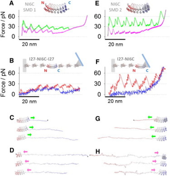
Mechanical anisotropy of NI6C. (A) The simulated unfolding trace (green) and refolding trace (pink) of NI6C-SMD1 (inset). The pulling geometry of NI6C-SMD1: terminal residues (gray dots) were subjected to stretching forces (adapted from Lee et al. (14)). (B) The AFM unfolding (red) and refolding (blue) traces of NI6C when (I27)3-NI6C-(I27)3 construct (inset) is stretched and relaxed without unfolding I27 domains (adapted from Lee et al. (14)). (C) Unfolding trajectory snapshots of NI6C-SMD1. Repeats were peeled off sequentially from the C-terminus to the N-terminus (direction II). (D) Refolding trajectory snapshots of NI6C-rSMD1. Repeats were refolded sequentially from the N-terminus to the C-terminus (direction IV). (E) The simulated unfolding trace (green) and refolding trace (pink) of NI6C-SMD2 (inset). The pulling geometry of NI6C-SMD2: the COM of the C-terminal repeats (gray circle) and the N-terminal residue (gray dot) were subjected to stretching forces. (F) The AFM unfolding (red) and refolding (blue) traces of NI6C when (I27)3-NI6C construct (inset) is stretched and relaxed. (G) Unfolding trajectory snapshots of NI6C-SMD2. Repeats were peeled off sequentially from the N-terminus to the C-terminus (direction I). (H) Refolding trajectory snapshots of NI6C-rSMD2. Repeats were refolded sequentially from the C-terminus to the N-terminus (pink arrow, direction III).
To test if it is possible to force the unfolding of ARs in NI6C in the opposite direction, we carried out new CG-SMD simulations in which the N-terminus residue and the center-of-mass (COM) of two C-terminal repeats of NI6C were subjected to stretching forces (NI6C-SMD2, Fig. 2 E, inset). It is clear that the unfolding forces originating from the new pulling geometry are significantly greater than the forces determined previously (∼60 pN vs. ∼30 pN, green traces in Fig. 2, A and E). Interestingly, the refolding forces captured in NI6C-SMD2 are significantly smaller than the refolding forces in NI6C-SMD1 (∼13 pN vs. ∼20 pN, pink traces in Fig. 2, A and E). A few snapshots of NI6C structure during the unfolding and refolding processes in NI6C-SMD2 are shown in Fig. 2, G and H, respectively. It is evident that repeats were peeled off and unfolded sequentially from the N-terminus to the C-terminus (Fig. 2 G), and repeats were refolded sequentially from the C-terminus to the N-terminus (Fig. 2 H). In this case, the repeats around COM (at the C-terminus) formed a folding nucleus. This is understandable, considering that the repeats past the COM point were not subjected to the stretching force at the end of the unfolding (or beginning of the refolding) simulation.
To verify these observations, we engineered another construct (I27)3-NI6C (Fig. 2 F, inset) in which the NI6C protein was flanked by I27 handles only on the N-terminal side. This design ensures that in AFM measurements, the stretching forces will be applied precisely to the N-terminal residue and to some random area close to the C-terminus of NI6C, similar to the pulling geometry in NI6C-SMD2. In Fig. S1, A and B (see the Supporting Material), we show typical AFM force-extension data of (I27)3-NI6C constructs that captured the characteristic force peaks of I27 domains after smaller force peaks that can be attributed to ARs of NI6C. The unfolding force peaks are similar to those determined by NI6C-SMD2 simulation, and at ∼60 pN are approximately twice as high as those measured by AFM when NI6C was stretched by its termini (Fig. 2 B). Fig. S1, E and F, shows the comparisons between unfolding and refolding traces captured by AFM and by NI6C-SMD2.The refolding force peaks were not resolved in these measurements (Fig. 2 F), consistent with the SMD2 results that predicted very small refolding force peaks of ∼13 pN. The agreement between the NI6C-SMD2 and AFM results obtained on the construct (I27)3-NI6C suggests that when the peeling process at the C-terminus is inhibited, the unfolding process may indeed start at the N-terminus and can propagate toward the C-terminus.
We note that in previous studies of globular proteins their mechanical anisotropy was observed when the proteins or their parts were subjected to forces acting in different pulling directions relative to the N-C axis (19). In our AFM and SMD experiments, the pulling direction remained practically constant and parallel to the N-C direction. The anisotropy revealed itself when, by pulling at a group of terminal atoms rather than a single atom, we likely inhibited the peeling process that would normally start at the C-terminus and possibly forced it to start at the N-terminus. Thus, in our work, the mechanical anisotropy of NI6C seems to be related to the sense of unfolding/refolding propagation direction (from C-to-N or N-to-C). However, we cannot presently exclude the possibility that in our AFM experiments the unfolding process was initiated in the middle of the NI6C stack and not at the termini. Further experiments to verify our CG-SMD simulations are warranted. One approach envisions mutating ARs, or inserting reporters in different parts of the NI6C stack to pinpoint the location of the origin of the unfolding process and its propagation directions under various pulling geometry conditions. These future measurements should further clarify the origin of the observed mechanical anisotropy of ARs.
Mechanical anisotropy of D34
CG SMD simulations of mechanical unfolding of D34
Three different pulling geometries for D34 (Fig. 3, A–C, insets) were explored: D34-SMD1, D34-SMD2, and D34-SMD3. Each case was repeated five times, and the simulations produced converged and consistent results.
In the D34-SMD1 case, forces were applied to the N-terminal residue Leu403 of R13 and the last residue of R24, Glu792, that precedes the SBD fragment (gray dots in Fig. 3 A, inset). With this setup, the D34 was stretched by the ends but no force was directly exerted on the SBD fragment. The corresponding force-extension curve (green trace in Fig. 3 A) displayed a set of even unfolding force peaks of ∼60 pN spaced by ∼3 nm and ∼7 nm. Fig. 3 D shows a few snapshots of D34 structure during this SMD unfolding trajectory (see Movie S1 in the Supporting Material). When stretched, the repeats peeled off sequentially from the N-terminus to the C-terminus (Fig. 3 D, direction I) while the SBD fragment remained folded and attached to the R20–R24 segment. The SBD fragment detached and unfolded only after R22 unfolded. Extensions 0–60 nm represent the unfolding of R13–R18 (D3), and the following region, from 60 to 110 nm, represents the unfolding of R19–R24 (D4). R13–R18 unfolded in two steps, generating a pair of split peaks. When loop-hairpins unfolded, they contributed an extension of ∼3 nm, and when two α-helices unfolded, they contributed ∼7 nm. R19–R21 of D4 also unfolded in a similar two-step fashion producing slightly higher force peaks (∼60 pN) as compared with the D3 region (∼55 pN). The ∼60 pN force peak at the extension of ∼90 nm corresponds to the simultaneous unfolding of R22, R23, H1 of R24, and SBD (at 84 ns in D34-SMD1). The last force peak of ∼40 pN at ∼100-nm extension corresponds to the unfolding of the last tertiary structure element composed of R22 and H1 of R23 (at 92 ns in D34-SMD1). It appears that the application of force to R24 does not strain the SBD fragment, which remains firmly attached to R20–R24, mechanically protecting the C-terminal region of D34. This in turn forces the unfolding to start at the N-terminus.
When forces were applied to terminal residues (the N-terminal residue Leu403 and the C-terminal residue Glu812) as shown in Fig. 3 B (inset, case D34-SMD2), the resulting force-extension curve (green trace in Fig. 3 B) displayed the first force peak of ∼35 pN at an extension of ∼6 nm. This was followed by two sets of force peaks and a plateau followed by a region of high stiffness (extensions >120 nm) indicative of a fully stretched polypeptide chain. Surprisingly, larger force peaks (∼45 pN) at extensions of up to 50 nm preceded smaller force peaks (∼30 pN) that occurred at extensions of 50∼90 nm. This result is quite unusual because, typically in force spectroscopy of proteins, smaller force peaks precede larger force peaks but not vice versa (19,46–48). Fig. 3 F shows a few snapshots of D34 during the SMD2 unfolding trajectory (see Movie S2). When stretched, the SBD fragment was detached first from the AR stack, producing the first force peak of ∼35 pN at an extension of ∼6 nm, and was aligned with the direction of the force. Then, the repeats were peeled off and unfolded sequentially from the C-terminal region to the N-terminal region (direction II). The unfolding events involving R24 to R21 that belong to D4 domain of D34 produced relatively large force peaks of ∼45 pN, and each force peak reported unfolding of one repeat. The unfolding of R20 to R13 produced relatively small force peaks of ∼30 pN spaced less regularly compared to the unfolding of R21–R24. During these events, repeats did not unfold in an all-or-none fashion, but unfolded in steps that involve the peeling off of helices and loop-hairpins.
Finally, in the D34-SMD3 case, forces were applied to the COMs of the terminal repeats (COM1 of R13-R14 and COM2 of R23-R24; gray circles in Fig. 3 C, inset). The resulting force-extension curve (green trace in Fig. 3 C) displayed a peak of 65 pN at an extension of ∼6 nm. This was followed by a set of ∼30 pN force peaks at extensions between 20 and 50 nm, which were then followed by a set of ∼60 pN force peaks. The ∼30 pN force peaks were spaced less regularly than the ∼60 pN force peaks, which were spaced by ∼10 nm. Fig. 3 H shows a few snapshots of D34 structure during this SMD3 unfolding trajectory (see Movie S3). The analysis of this trajectory indicates that the first force peak is associated with the stack-breaking event that separated D3 from D4 (interface between R18 and R19, Fig. 3 H, first panel). Then, the D3 fragment (R13–R18) unraveled sequentially from R18 toward R13 (Fig. 3 H, direction II) producing small unfolding force peaks of ∼30 pN Next, the D4 fragment (R19–R24) unraveled sequentially from R19 to R22 (Fig. 3 H, direction I) producing large ∼60 pN force peaks. It appears that in this pulling geometry, the weakest point of the protein is located in the center of the stack. As expected from solid mechanics for curved elements, the concentration of the stress is greatest in the center, and this simple observation explains why the stack breaks in the center and the unfolding process starts from there. Interestingly, a similar stack-breaking event of D34 (at the interface between repeat 18 and 19) followed by the unfolding of ARs was observed by Sotomayor et al. (12) in previous all-atom SMD simulations of D34.
SMD simulations of mechanical refolding of D34
The pink traces in Fig. 3, A–C, show the force-extension curves obtained from the reverse rSMD1, rSMD2, and rSMD3 simulations in which the starting configuration corresponded to the final conformation of the stretching SMD simulations. Fig. 3, E, G, and I, each show snapshots of D34 structure captured during the rSMD1, rSMD2, and rSMD3 trajectories (see Movie S4, Movie S5, and Movie S6). In each of these cases, the initial relaxing process involves the secondary structure (helices) formation that produces the characteristic force plateau of ∼30 pN in the relaxing force-extension curves (Fig. 3, A–C). After the relaxation following the plateau phase, the nucleation steps have occurred and were captured by the first refolding force peaks in rSMD1 (a relatively small refolding force peak at 66 nm) and rSMD2 (a relatively pronounced refolding force peak at 63 nm).
In rSMD1, two C-terminal repeats, R23-R24, nucleated within 33 ns (615–648 ns) and the SBD fragment immediately reattached to the folded repeats. In rSMD1, the growth of the nucleated structure proceeded uniformly toward the N-terminus with repeats refolding one by one. This process produced a set of small refolding force peaks of ∼13 pN (pink trace in Fig. 3 A, direction III).
In rSMD2, four ARs, R17–R20, nucleated within 4 ns (588–592 ns). The growth of the nucleated structure proceeded toward the C-terminus first (direction IV), and after all repeats on the C-terminal side (R21–R24) were folded, the N-terminal side repeats (R16–R13) folded sequentially (direction III). The first process produced robust and regular refolding force peaks (∼20 pN, direction IV), and the second process produced somewhat smaller and less regular force peaks (direction III). Finally, the reattachment of SBD to the AR stack produced a pronounced force peak of ∼25 pN, which overlaps with the first force peak in the unfolding force curve that captured the unbinding of SBD from the stack.
In rSMD3 that started with the terminal repeat(s) partially folded (R13 in the N-terminus and R23-R24 in the C-terminus, the first snapshot in Fig. 3 I), the nucleation step did not occur. Interestingly, a single repeat R13, rather than the stably folded tandem R23-R24, served as a folding template (i.e., a foldon). Repeats R14–R22 refolded and attached to the folded N-terminal side repeat (R13), sequentially (Fig. 3 I, direction IV). The large ∼50 pN refolding force peak at an extension of ∼8 nm captured the creation of the interface between folded AR stacks of R23-R24 and R13–R22, which completed the refolding process of D34. This refolding force peak is similar to the first unfolding force peak that captured the initial breaking of the stack.
In summary, when ARs reattach to the C-terminal side of the folded repeats (direction IV, Fig. 3, G and I), refolding events produce large force peaks of ∼20 pN. However, when refolding proceeds in the opposite direction (direction III, Fig. 3 E, reattaching ARs to the N-terminal side of the folded repeats), these events produce small force peaks of ∼13 pN. The folding direction is dictated by the location of the nucleation step in the polypeptide structure.
The analysis of native contacts within helical bundles during unfolding
To investigate the origin of the mechanical anisotropy of D34, we analyzed in detail the number of native contacts in helical bundles of the coarse-grained D34 structure (Fig. 4 C).
Figure 4.
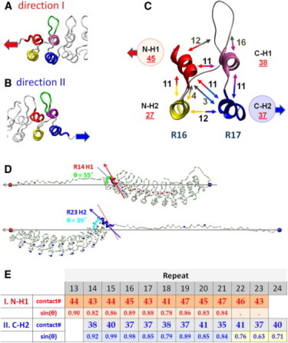
Analysis of native contacts that break in a helical bundle in unfolding pathways I and II. (A) A ribbon diagram of ARs when a single AR is peeled off in direction I. H1 unfolds before H2 of the same repeat. (B) A ribbon diagram of ARs when a single AR is peeled off in direction II. H2 unfolds before H1 of the same repeat. (C) A ribbon diagram of R16-R17 with the number of native contacts between helices and the loop-hairpin structure connecting the repeats. (Double-sided arrow) Two interacting partners that form native contacts (number of contacts displayed by the arrows). (D) (Top) In SMD2, the angle between two vectors: the SMD vector (defined by residue 1 and 388, horizontal arrow) and the vector of H1 of R14 (slanted arrow) is 55°. (Bottom) In SMD1, the angle between the SMD vector (residues 1 and 408, horizontal arrow) and the vector of H2 of R23 (slanted arrow) is 39°. (Dashed line) R14-H1 vector, shown for comparison. (E) Table shows the analysis of contact numbers and angles of helices for all helical bundles when unfolding in directions I and II.
When an AR unfolds at the N-terminal side of the stack, helix N-H1 must be detached first from the stack as shown in Fig. 4 A (direction I). For example, to peel off N-H1 of repeat R16 from the stack, 45 native contacts (12+11+11+11) must be ruptured (Fig. 4, A and C). When the C-terminal side repeats detach and unfold from the stack, C-H2 must be detached first as shown in Fig. 4, B and C (direction II). For instance, 37 contacts (11+11+3+12) must be ruptured to peel off helix C-H2 of repeat R17 (Fig. 4 C). Similar analyses were conducted for all helical bundles in D34 (see table in Fig. 4 E). The table shows that greater numbers of contacts need to be ruptured to unravel ARs in direction I than in the opposite direction II.
In SMD2, the unfolding forces of R24–R21 were higher than the unfolding forces of R20–R13 (∼45 pN vs. 30 pN). These different levels of unfolding forces can be partially accounted for by the different number of contacts in both segments. To fully explain these differences, we need to consider the stack geometry and its changes during unfolding. Because of the stack curvature, different repeats are pulled at different angles by the external forces, and this angle varies with the progression of the unfolding (Fig. 4 D). For example, right before detachment, H2 of R23 is pulled at an angle of 39°, which is significantly smaller than the optimal angle of 90°. However, after the unfolding of three repeats (R22–R24), the C-H2 of R21 was pulled at a significantly greater angle of 60°, and required less force for unfolding. To reflect this effect along with the number of contacts, we tabulated the sine of the pulling angle (θ) in Fig. 4 E. It is interesting that in pulling direction I, the pulling angle was constant, ∼60° throughout the unfolding process. We estimate that, on average, the angle effect contributes ∼20% to the difference of the unfolding forces of D34 in pulling direction II (sin(θ = 45°)/sin(θ = 60°) = 0.82).
The analysis of native contacts during refolding
To understand the origin of the refolding anisotropy of ARs, we carefully examined the D34 trajectories corresponding to rSMD1, rSMD2, and rSMD3 and determined the dynamics of contact formation.
Fig. 5 A shows three snapshots of the rSMD1 simulation leading to the refolding of R16. ARs refolded by reattaching to the folding nucleus that formed at the C-terminus (direction III). The same refolding direction was also observed during the late phase of rSMD2 (Fig. 3 G) after the C-terminal part of the protein folded completely. Interestingly, the refolding process in rSMD1 was accompanied by spontaneous formation and opening of hairpins or antiparallel helices (H1-H2) on the N-terminal side of the stack (arrows in Fig. 5 A, middle panel). For example, during the time window from 973 ns to 1010 ns in rSMD1, two loop-hairpins of R14 and R15 and a pair of antiparallel helices (H1-H2) of R13 formed spontaneously one by one (arrows, Fig. 5 A). Then, within 2 ns, R16 reattached to the stack (oval shape in Fig. 5 A, bottom panel), reforming 83 native contacts while the transiently folded structures opened with a loss of 22 contacts. While the refolding of one repeat is expected to contract the polypeptide chain by ∼11 nm, the observed net contraction during the 2-ns step was only 0.3 nm, because of the opening of the transiently folded structures in R13-R14. Because of this very small net contraction length accompanying the refolding of R16, the increase in the tension of D34 was modest and generated a medium refolding force peak of ∼16 pN. A detailed analysis of the refolding process in direction III reveals that differences in the number of contacts that could form in a given refolding step at the stack/chain interface, compared to the number of possible contacts that could form transiently elsewhere, determine whether this refolding step occurs (for details, see the Supporting Material).
Figure 5.
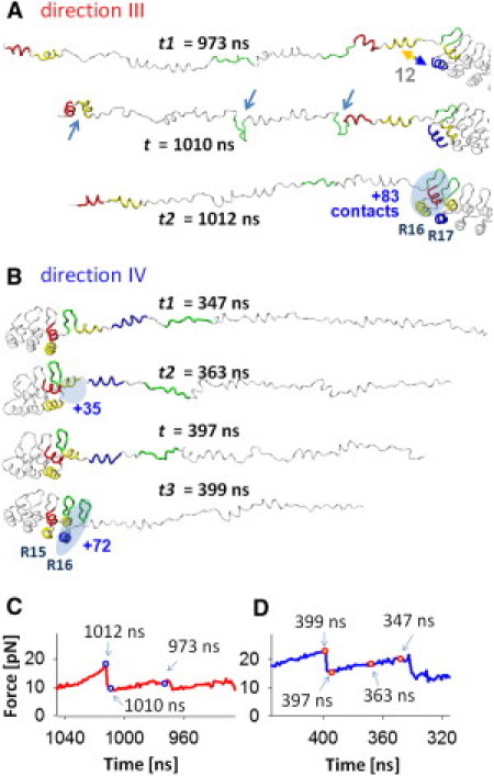
Structures and native contacts for refolding pathways D34 fragments in directions III and IV. (A) Snapshots of the refolding trajectory of the R13-R19 region of the D34 fragment in rSMD1 at t = 973 ns (top), 1010 ns (middle), and 1012 ns (bottom). In this refolding process, H1 and H2 of R16 and the loop of R15 refold simultaneously and reconstruct 64 contacts at t = 1012 ns. At t = 1010 ns, two loop-hairpins (of R14 and R15) and one H1-H2 pair (of R13) are formed. At the refolding event of the R16 loop, R17- H1/H2 (t = 1012 ns), the locally folded structures in R13-R14 straighten. Note the resulted refolding force peaks were medium (16 pN, as shown in panel C). (B) Snapshots of the refolding trajectory of the R13–R18 region in rSMD3 at t = 347 ns, 363 ns, 397 ns, and 399 ns. At t = 363 ns, the H1of R16 refolded and reconstructed 35 contacts. At t = 397∼399 ns, the R16-H2 and loop refolded and reconstructed 72 contacts. Note the resulted refolding force peaks were relatively high (23 pN as shown in panel D). (C) The force-time curve corresponding to the refolding trajectory shown in panel A. (D) The force-time curve corresponding to the refolding trajectory shown in panel B.
In Fig. 5 B, we show snapshots of the R16 refolding process in direction IV extracted from the rSMD3 trajectory. In contrast to rSMD1, in rSMD3, ARs refolded by reattaching to the folding nucleus that formed at the N-terminus. This refolding direction also corresponds to the initial phase of refolding simulation rSMD2 (Fig. 3 G). We begin our analysis immediately after H2 and loop-hairpin structure of R15 refolded at 347 ns in rSMD3. At 363 ns, H1 of R16 refolded, forming 35 contacts. The stacking of R16-H1 to the R13–R15 reforms many more contacts as compared to the number of contacts in possible transient structures (for details, see the Supporting Material). Therefore, these transient structures did not occur and R16-H1 remained folded during the further relaxation process until the tension in D34 reached its minimum at 397 ns. Then, within 2 ns (397–399 ns), H2 and the loop-hairpin structure of R16 refolded, reforming 72 more native contacts. This step, which generated a significant refolding force peak of 22 pN, completes the refolding of R16. Importantly, the refolding process in direction III occurred without any transient structure formation elsewhere in the polypeptide chain, and as a result, the tension in D34 during the entire refolding process was greater than the tension during the refolding in direction III (Fig. 5, C and D).
AFM measurements of D34
We carried out AFM measurements on a D34 monomer and a number of constructs of D34 with I27 handles. We analyze here only the AFM measurements of D34 monomers, because D34-I27 constructs did not produce consistent results (for details, see the Supporting Material).
In Fig. 6, we show examples of stretching and relaxing traces of the D34 monomer. The stretching trace shown in Fig. 6 A is composed of a set of regular unfolding force peaks of ∼60 pN. Other stretching cycles obtained on the same molecule showed similar force peak patterns. The stretching trace obtained from another molecule shown in Fig. 6 B also showed a series of unfolding force peaks of 40∼60 pN, whose contour length increments (ΔLc) match reasonably well with the unfolding trace in Fig. 6 A (dotted-line superimposed in Fig. 6 B). The histograms of the unfolding force (Funfold) and ΔLc are shown in Fig. 6 D; the average, Funfold, was 57 ± 27 pN and the average ΔLc was 8.8 ± 4.9 nm. In addition, we also recorded force-extension curves that contain significantly smaller and less discernible unfolding force peaks of ∼30 pN (at extensions of 0–40 nm, Fig. 6 C). The unfolding trace of Fig. 6 A is superimposed in Fig. 6 C (dotted line). It is clear that the large ∼60 pN unfolding force peaks at extensions >40 nm are similar in both traces, suggesting similar unfolding events at these extensions. In Fig. S2 A, we compared the AFM unfolding force-extension curves shown in Fig. 6 A with the unfolding trace of D34-SMD1 (Fig. 3 A), which captured the unfolding process in direction I (peeling ARs from the N-terminus side of the stack). Both traces are very similar, suggesting that, in the AFM measurement, the unfolding occurred in the same direction. Fig. S2 B compares the AFM force-extension curve of Fig. 6 C with the unfolding trace of D34-SMD3 (Fig. 3 C), in which the stack broke in the middle and unfolding proceeded first in direction II (peeling ARs toward the N-terminus side of the stack) and then in the opposite direction. The similarity of AFM and SMD traces suggests that the unfolding process under the AFM control may have also occurred in two phases in opposite directions.
Figure 6.
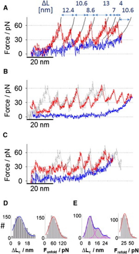
Unfolding and refolding force-extension traces of D34. (A) The unfolding and refolding traces of D34 obtained by AFM. Unfolding force peaks were fitted with worm-like chain curves (persistence length ∼0.7 nm). Note the pronounced refolding force peaks. (B) The unfolding and refolding traces of another D34 molecule obtained by AFM. (Dotted-line trace) The unfolding trace in panel A is superimposed. Note the absence of pronounced refolding force peaks. (C) The unfolding and refolding traces of another D34 molecule obtained by AFM. (Dotted-line trace) The unfolding trace in panel A is superimposed. Note that the unfolding force peaks at the extension >40 nm match reasonably well with the force peaks of the unfolding trace shown in panel A. (D) Histograms of the contour length increment ΔLc and unfolding forces Funfold with Gaussian distribution fits. The average ΔLc of unfolding force peaks was 8.8 ± 4.9 nm, the average Funfold was 57 ± 27 pN (number of observations, N = 1123). (E) Histograms of the contraction length ΔLc and the refolding forces Frefold with Gaussian distribution fits. The average ΔLc of refolding was 8 nm, 16 nm, and 24 nm. The average Frefold was 26 ± 11 pN (number of observations, N = 543).
Mechanically unfolded D34 monomers were relaxed to capture the refolding behavior of D34. We observed two types of refolding force-extension curves: some recordings showed refolding force peaks (Fig. 6 A) while others did not register clear refolding force peaks (Fig. 6 B). We analyzed the more pronounced refolding force peaks of D34 similar to those shown in Fig. 6 A. The average value of refolding force peaks was 26 ± 11 pN (force peaks were measured as the maximum force from the force baseline (Fig. S3 A)). The histogram of refolding length ΔLc, determined by worm-like chain fits, was fitted with three Gaussian curves centered at 8.5 nm, 16.5 nm, and 24 nm, which are presumably the contraction length of one, two, and three ARs, respectively. In Fig. S3, B and C, we compared the two AFM refolding traces shown in Fig. 6, A and B, with the refolding force spectrograms obtained from simulations rSMD1 and rSMD3, respectively, and conclude a qualitative agreement between theory and experimental data. More AFM measurements with a better control over pulling geometry of D34 are warranted to rigorously test the SMD results.
Mechanical behavior of D34 in vivo
The analysis of the mechanical behavior of D34 performed above captured hitherto unrecognized intrinsic mechanical anisotropy of ARs. We speculate that this anisotropy of the helical bundle has been exploited in evolution to produce an intricate mechanical design of ankyrin-R and other proteins including ARs, allowing them to adjust their mechanical stability and elastic properties to the levels required to perform their biological functions in mediating protein-protein interactions and possibly mechanotransduction.
In light of this anisotropy, one of the roles of the SBD could be to mechanically reinforce the C-terminal part of the protein, thus preventing the peeling off of ARs from that side. Then, the threshold of ∼60 pN for the unfolding ARs from the N-terminus side of the stack or breaking the stack in the middle may be high enough to allow D34 to endure the physiological stress during blood circulation without mechanical breakdown and unfolding of ARs. However, if the mechanical breakdown of D34 did occur under severe deformation (10), the unfolding of some ARs could provide the necessary length to decrease the tension (17) to preserve the intermolecular interactions of D34. Thus, the mechanical unfolding of a few ARs could work as a safety switch. ARs refolding could then be exploited to tightly regulate the length and tension of D34 to desired levels in a fashion that would be closely related to the details of the underlying unfolding process.
Conclusions
Our SMD study, corroborated by AFM results, reveals an unusual mechanical anisotropy of consensus and native ARs, which manifests itself by a different mechanical behavior when their unfolding (and refolding) is forced to propagate from the N-terminus toward the C-terminus as compared to the unfolding (refolding) in the opposite direction. The mechanics of D34 is additionally affected by the curvature of the stack and by the presence of its unique spectrin-binding domain segment. These complex mechanical properties of ARs in D34 may affect its behavior in vivo.
Acknowledgments
This work was supported by National Institutes of Health grant GM079663 to P.E.M. and V.B., and National Science Foundation grant MCB-0717770 to P.E.M. and W.Y. X.Z. has been supported with a Graduate Fellowship from the Center of Theoretical and Mathematical Sciences at Duke University.
Contributor Information
Vann Bennett, Email: benne012@mc.duke.edu.
Weitao Yang, Email: weitao.yang@duke.edu.
Piotr E. Marszalek, Email: piotr.marszalek@duke.edu.
Supporting Material
References
- 1.Görög P., Kovács I.B. Impaired red cell deformability in established adjuvant arthritic disease in rats. Agents Actions. 1980;10:427–430. doi: 10.1007/BF01968041. [DOI] [PubMed] [Google Scholar]
- 2.Schrier S. Hereditary Spherocytosis (HS) ASH Image Bank. 2001;2001:100214. [Google Scholar]
- 3.Bennett V., Baines A.J. Spectrin and ankyrin-based pathways: metazoan inventions for integrating cells into tissues. Physiol. Rev. 2001;81:1353–1392. doi: 10.1152/physrev.2001.81.3.1353. [DOI] [PubMed] [Google Scholar]
- 4.Scott K.A., Randles L.G., Clarke J. The folding pathway of spectrin R17 from experiment and simulation: using experimentally validated MD simulations to characterize States hinted at by experiment. J. Mol. Biol. 2006;359:159–173. doi: 10.1016/j.jmb.2006.03.011. [DOI] [PubMed] [Google Scholar]
- 5.Ortiz V., Nielsen S.O., Discher D.E. Unfolding a linker between helical repeats. J. Mol. Biol. 2005;349:638–647. doi: 10.1016/j.jmb.2005.03.086. [DOI] [PubMed] [Google Scholar]
- 6.Rief M., Pascual J., Gaub H.E. Single molecule force spectroscopy of spectrin repeats: low unfolding forces in helix bundles. J. Mol. Biol. 1999;286:553–561. doi: 10.1006/jmbi.1998.2466. [DOI] [PubMed] [Google Scholar]
- 7.Law R., Liao G., Discher D.E. Pathway shifts and thermal softening in temperature-coupled forced unfolding of spectrin domains. Biophys. J. 2003;85:3286–3293. doi: 10.1016/S0006-3495(03)74747-X. [DOI] [PMC free article] [PubMed] [Google Scholar]
- 8.Randles L.G., Rounsevell R.W.S., Clarke J. Spectrin domains lose cooperativity in forced unfolding. Biophys. J. 2007;92:571–577. doi: 10.1529/biophysj.106.093690. [DOI] [PMC free article] [PubMed] [Google Scholar]
- 9.Johnson C.P., Tang H.-Y., Discher D.E. Forced unfolding of proteins within cells. Science. 2007;317:663–666. doi: 10.1126/science.1139857. [DOI] [PMC free article] [PubMed] [Google Scholar]
- 10.Krieger C.C., An X., Discher D.E. Cysteine shotgun-mass spectrometry (CS-MS) reveals dynamic sequence of protein structure changes within mutant and stressed cells. Proc. Natl. Acad. Sci. 2011;108:8269–8274. doi: 10.1073/pnas.1018887108. [DOI] [PMC free article] [PubMed] [Google Scholar]
- 11.Michaely P., Tomchick D.R., Anderson R.G. Crystal structure of a 12 ANK repeat stack from human ankyrinR. EMBO J. 2002;21:6387–6396. doi: 10.1093/emboj/cdf651. [DOI] [PMC free article] [PubMed] [Google Scholar]
- 12.Sotomayor M., Corey D.P., Schulten K. In search of the hair-cell gating spring elastic properties of ankyrin and cadherin repeats. Structure. 2005;13:669–682. doi: 10.1016/j.str.2005.03.001. [DOI] [PubMed] [Google Scholar]
- 13.Lee G., Abdi K., Marszalek P.E. Nanospring behavior of ankyrin repeats. Nature. 2006;440:246–249. doi: 10.1038/nature04437. [DOI] [PubMed] [Google Scholar]
- 14.Lee W., Zeng X., Marszalek P.E. Full reconstruction of a vectorial protein folding pathway by atomic force microscopy and molecular dynamics simulations. J. Biol. Chem. 2010;285:38167–38172. doi: 10.1074/jbc.M110.179697. [DOI] [PMC free article] [PubMed] [Google Scholar]
- 15.Serquera D., Lee W., Itzhaki L.S. Mechanical unfolding of an ankyrin repeat protein. Biophys. J. 2010;98:1294–1301. doi: 10.1016/j.bpj.2009.12.4287. [DOI] [PMC free article] [PubMed] [Google Scholar]
- 16.Kim M., Abdi K., Marszalek P.E. Fast and forceful refolding of stretched α-helical solenoid proteins. Biophys. J. 2010;98:3086–3092. doi: 10.1016/j.bpj.2010.02.054. [DOI] [PMC free article] [PubMed] [Google Scholar]
- 17.Li L., Wetzel S., Fernandez J.M. Stepwise unfolding of ankyrin repeats in a single protein revealed by atomic force microscopy. Biophys. J. 2006;90:L30–L32. doi: 10.1529/biophysj.105.078436. [DOI] [PMC free article] [PubMed] [Google Scholar]
- 18.Mickler M., Dima R.I., Rief M. Revealing the bifurcation in the unfolding pathways of GFP by using single-molecule experiments and simulations. Proc. Natl. Acad. Sci. USA. 2007;104:20268–20273. doi: 10.1073/pnas.0705458104. [DOI] [PMC free article] [PubMed] [Google Scholar]
- 19.Dietz H., Berkemeier F., Rief M. Anisotropic deformation response of single protein molecules. Proc. Natl. Acad. Sci. USA. 2006;103:12724–12728. doi: 10.1073/pnas.0602995103. [DOI] [PMC free article] [PubMed] [Google Scholar]
- 20.Junker J.P., Rief M. Single-molecule force spectroscopy distinguishes target binding modes of calmodulin. Proc. Natl. Acad. Sci. USA. 2009;106:14361–14366. doi: 10.1073/pnas.0904654106. [DOI] [PMC free article] [PubMed] [Google Scholar]
- 21.Bertz M., Rief M. Ligand binding mechanics of maltose binding protein. J. Mol. Biol. 2009;393:1097–1105. doi: 10.1016/j.jmb.2009.08.066. [DOI] [PubMed] [Google Scholar]
- 22.Lu H., Schulten K. Steered molecular dynamics simulations of force-induced protein domain unfolding. Proteins. 1999;35:453–463. [PubMed] [Google Scholar]
- 23.Lu H., Schulten K. The key event in force-induced unfolding of Titin's immunoglobulin domains. Biophys. J. 2000;79:51–65. doi: 10.1016/S0006-3495(00)76273-4. [DOI] [PMC free article] [PubMed] [Google Scholar]
- 24.Isralewitz B., Baudry J., Schulten K. Steered molecular dynamics investigations of protein function. J. Mol. Graph. Model. 2001;19:13–25. doi: 10.1016/s1093-3263(00)00133-9. [DOI] [PubMed] [Google Scholar]
- 25.Gao M., Lu H., Schulten K. Simulated refolding of stretched titin immunoglobulin domains. Biophys. J. 2001;81:2268–2277. doi: 10.1016/S0006-3495(01)75874-2. [DOI] [PMC free article] [PubMed] [Google Scholar]
- 26.Best R.B., Fowler S.B., Clarke J. Mechanical unfolding of a titin Ig domain: structure of transition state revealed by combining atomic force microscopy, protein engineering and molecular dynamics simulations. J. Mol. Biol. 2003;330:867–877. doi: 10.1016/s0022-2836(03)00618-1. [DOI] [PubMed] [Google Scholar]
- 27.Sotomayor M., Schulten K. Single-molecule experiments in vitro and in silico. Science. 2007;316:1144–1148. doi: 10.1126/science.1137591. [DOI] [PubMed] [Google Scholar]
- 28.Li M.S., Hu C.-K., Thirumalai D. Multiple stepwise refolding of immunoglobulin domain I27 upon force quench depends on initial conditions. Proc. Natl. Acad. Sci. USA. 2006;103:93–98. doi: 10.1073/pnas.0503758103. [DOI] [PMC free article] [PubMed] [Google Scholar]
- 29.Hyeon C., Dima R.I., Thirumalai D. Pathways and kinetic barriers in mechanical unfolding and refolding of RNA and proteins. Structure. 2006;14:1633–1645. doi: 10.1016/j.str.2006.09.002. [DOI] [PubMed] [Google Scholar]
- 30.Ammenti A., Cecconi F., Vulpiani A. A statistical model for translocation of structured polypeptide chains through nanopores. J. Phys. Chem. B. 2009;113:10348–10356. doi: 10.1021/jp900947f. [DOI] [PubMed] [Google Scholar]
- 31.Kirmizialtin S., Ganesan V., Makarov D.E. Translocation of a β-hairpin-forming peptide through a cylindrical tunnel. J. Chem. Phys. 2004;121:10268–10277. doi: 10.1063/1.1807832. [DOI] [PubMed] [Google Scholar]
- 32.Makarov D.E. Computer simulations and theory of protein translocation. Acc. Chem. Res. 2009;42:281–289. doi: 10.1021/ar800128x. [DOI] [PubMed] [Google Scholar]
- 33.Tian P., Andricioaei I. Repetitive pulling catalyzes co-translocational unfolding of barnase during import through a mitochondrial pore. J. Mol. Biol. 2005;350:1017–1034. doi: 10.1016/j.jmb.2005.05.035. [DOI] [PubMed] [Google Scholar]
- 34.West D.K., Brockwell D.J., Paci E. Prediction of the translocation kinetics of a protein from its mechanical properties. Biophys. J. 2006;91:L51–L53. doi: 10.1529/biophysj.106.089490. [DOI] [PMC free article] [PubMed] [Google Scholar]
- 35.Oberhauser A.F., Marszalek P.E., Fernandez J.M. The molecular elasticity of the extracellular matrix protein tenascin. Nature. 1998;393:181–185. doi: 10.1038/30270. [DOI] [PubMed] [Google Scholar]
- 36.Rief M., Gautel M., Gaub H.E. Reversible unfolding of individual titin immunoglobulin domains by AFM. Science. 1997;276:1109–1112. doi: 10.1126/science.276.5315.1109. [DOI] [PubMed] [Google Scholar]
- 37.Marszalek P.E., Lu H., Fernandez J.M. Mechanical unfolding intermediates in titin modules. Nature. 1999;402:100–103. doi: 10.1038/47083. [DOI] [PubMed] [Google Scholar]
- 38.Junker J.P., Ziegler F., Rief M. Ligand-dependent equilibrium fluctuations of single calmodulin molecules. Science. 2009;323:633–637. doi: 10.1126/science.1166191. [DOI] [PubMed] [Google Scholar]
- 39.Li H.B., Linke W.A., Fernandez J.M. Reverse engineering of the giant muscle protein titin. Nature. 2002;418:998–1002. doi: 10.1038/nature00938. [DOI] [PubMed] [Google Scholar]
- 40.Lv S., Dudek D.M., Li H. Designed biomaterials to mimic the mechanical properties of muscles. Nature. 2010;465:69–73. doi: 10.1038/nature09024. [DOI] [PubMed] [Google Scholar]
- 41.Oberhauser A.F., Carrión-Vázquez M. Mechanical biochemistry of proteins one molecule at a time. J. Biol. Chem. 2008;283:6617–6621. doi: 10.1074/jbc.R700050200. [DOI] [PMC free article] [PubMed] [Google Scholar]
- 42.Carrion-Vazquez M., Li H.B., Fernandez J.M. The mechanical stability of ubiquitin is linkage dependent. Nat. Struct. Biol. 2003;10:738–743. doi: 10.1038/nsb965. [DOI] [PubMed] [Google Scholar]
- 43.Werbeck N.D., Rowling P.J.E., Itzhaki L.S. Shifting transition states in the unfolding of a large ankyrin repeat protein. Proc. Natl. Acad. Sci. USA. 2008;105:9982–9987. doi: 10.1073/pnas.0705300105. [DOI] [PMC free article] [PubMed] [Google Scholar]
- 44.Werbeck N.D., Itzhaki L.S. Probing a moving target with a plastic unfolding intermediate of an ankyrin-repeat protein. Proc. Natl. Acad. Sci. USA. 2007;104:7863–7868. doi: 10.1073/pnas.0610315104. [DOI] [PMC free article] [PubMed] [Google Scholar]
- 45.Wetzel S.K., Settanni G., Plückthun A. Folding and unfolding mechanism of highly stable full-consensus ankyrin repeat proteins. J. Mol. Biol. 2008;376:241–257. doi: 10.1016/j.jmb.2007.11.046. [DOI] [PubMed] [Google Scholar]
- 46.Li H., Oberhauser A.F., Fernandez J.M. Atomic force microscopy reveals the mechanical design of a modular protein. Proc. Natl. Acad. Sci. USA. 2000;97:6527–6531. doi: 10.1073/pnas.120048697. [DOI] [PMC free article] [PubMed] [Google Scholar]
- 47.Ng S.P., Billings K.S., Clarke J. Designing an extracellular matrix protein with enhanced mechanical stability. Proc. Natl. Acad. Sci. USA. 2007;104:9633–9637. doi: 10.1073/pnas.0609901104. [DOI] [PMC free article] [PubMed] [Google Scholar]
- 48.Oberhauser A.F., Ohashi T., Fernandez J.M. The micromechanics of single fibronectin proteins studied with atomic force microscopy. Biophys. J. 2000;78:447A. [Google Scholar]
- 49.Bustamante C., Marko J.F., Smith S. Entropic elasticity of λ-phage DNA. Science. 1994;265:1599–1600. doi: 10.1126/science.8079175. [DOI] [PubMed] [Google Scholar]
- 50.Florin E.L., Rief M., Gaub H.E. Sensing specific molecular-interactions with the atomic-force microscope. Biosens. Bioelectron. 1995;10:895–901. [Google Scholar]
- 51.Schmid E.L., Keller T.A., Vogel H. Reversible oriented surface immobilization of functional proteins on oxide surfaces. Anal. Chem. 1997;69:1979–1985. doi: 10.1021/ac9700033. [DOI] [PubMed] [Google Scholar]
- 52.Clementi C., Nymeyer H., Onuchic J.N. Topological and energetic factors: what determines the structural details of the transition state ensemble and “en-route” intermediates for protein folding? An investigation for small globular proteins. J. Mol. Biol. 2000;298:937–953. doi: 10.1006/jmbi.2000.3693. [DOI] [PubMed] [Google Scholar]
- 53.Schmitt L., Ludwig M., Tampé R. A metal-chelating microscopy tip as a new toolbox for single-molecule experiments by atomic force microscopy. Biophys. J. 2000;78:3275–3285. doi: 10.1016/S0006-3495(00)76863-9. [DOI] [PMC free article] [PubMed] [Google Scholar]
- 54.Steward A., Toca-Herrera J.L., Clarke J. Versatile cloning system for construction of multimeric proteins for use in atomic force microscopy. Protein Sci. 2002;11:2179–2183. doi: 10.1110/ps.0212702. [DOI] [PMC free article] [PubMed] [Google Scholar]
- 55.MacKerell A.D., Jr., Feig M., Brooks C.L., 3rd Extending the treatment of backbone energetics in protein force fields: limitations of gas-phase quantum mechanics in reproducing protein conformational distributions in molecular dynamics simulations. J. Comput. Chem. 2004;25:1400–1415. doi: 10.1002/jcc.20065. [DOI] [PubMed] [Google Scholar]
- 56.Rabbi, M., and P.E. Marszalek. 2007. Measuring protein mechanics by atomic force microscopy. Cold Spring Harb. Protoc. 2007:pdb.prot4901. [DOI] [PubMed]
Associated Data
This section collects any data citations, data availability statements, or supplementary materials included in this article.