Abstract
Optical coherence tomography allows for dynamic, three-dimensional (3D+T) imaging of the heart within animal embryos. However, direct 3D+T imaging frame rates remain insufficient for cardiodynamic analysis. Previously, this limitation has been addressed by reconstructing 3D+T representations of the beating heart based on sets of two-dimensional image sequences (2D+T) acquired sequentially at high frame rate and in fixed (and parallel) planes throughout the heart. These methods either require additional hardware to trigger the acquisition of each 2D+T series to the same phase of the cardiac cycle or accumulate registration errors as the slices are synchronized retrospectively by pairs, without a gating signal. Here, we present a sequential turning acquisition and reconstruction (STAR) method for 3D+T imaging of periodically moving structures, which does not require any additional gating signal and is not prone to registration error accumulation. Similarly to other sequential cardiac imaging methods, multiple fast image series are consecutively acquired for different sections but in between acquisitions, the imaging plane is rotated around the center line instead of shifted along the direction perpendicular to the slices. As the central lines of all image-sequences coincide and represent measurements of the same spatial position, they can be used to accurately synchronize all the slices to a single inherent reference signal. We characterized the accuracy of our method on a simulated dynamic phantom and successfully imaged a beating embryonic rat heart. Potentially, this method can be applied for structural or Doppler imaging approaches with any direct space imaging modality such as computed tomography, ultrasound, or light microscopy.
OCIS codes: (110.4500) Optical coherence tomography, (180.1655) Coherence tomography, (110.4155) Multiframe image processing, (170.4500) Optical coherence tomography, (100.0100) Image processing
1. Introduction
Studies of cardiac development and function increasingly rely on the ability to image the beating embryonic heart in three dimensions at high frame rate. Optical coherence tomography (OCT) allows for non-destructive imaging through several millimeters of biological tissue with single cell resolution. It is being adopted as an accurate imaging method to study in vivo systems, as it provides both information on structure and dynamics. OCT has been used to image whole mammalian and avian embryos [1, 2], measure flow in the vasculature [3, 4], and image the mammalian and avian embryonic hearts in 4D [5–7].
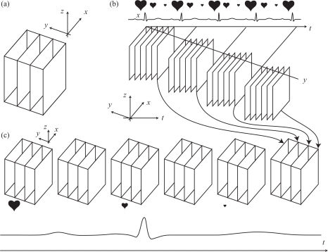
Direct acquisition of volumetric (3D) OCT data, which involves scanning a beam along two directions and remains too slow for imaging fast moving structures such as cardio-vascular structures or the beating heart. Insufficient frame rates lead to image artifacts, such as motion blur, which prevent fine characterization of morphology and function. However, since cardiac structures move periodically, indirect imaging methods can be used to produce 3D+T renderings at high frame rates. One approach consists in acquiring 2D+T image bursts in fixed planes throughout the heart, each lasting the duration of a few heartbeat cycles. When the imaging planes (all parallel) are separated by a small distance, each sequence can be synchronized to its neighbors to finally produce a 3D+T data set of the beating heart with a frame rate identical to that of the 2D+T sequences (Fig. 1). This approach has been used in confocal microscopy [8,9] and OCT [5,6]. This technique is particularly attractive because reconstruction is possible based only on the imaging data itself. However, since the reconstruction proceeds by synchronizing image sequences recursively from one imaging plane to the next, this method is susceptible to error propagation.
Fig. 1.
Sequential acquisition using parallel slice geometry [8,9,5]. (a) Direct 3D volume is obtained by collecting multiple B-scans (y-planes) (b) Sequential imaging of fast B-scans at a fixed y-positions (c) If triggered at the same time in the heart cycle, or subsequently synchronized, the frames can be re-assembled to form a 3D+time series at high frame rate.
Alternatives to this image-intrinsic reconstruction is to use a separate gating signal so imaging can be triggered at a precise time in the cardiac cycle. Known as prospective gating in magnetic resonance imaging (MRI) and X-ray computed tomography (CT) [10–14], gated cardiac imaging does not rely on post-acquisition synchronization but usually requires additional hardware to collect the gating signal. In OCT, gated imaging has been implemented by at least two research groups [15, 16], yet it is particularly challenging since two independent OCT scanning heads have to be aligned around the tiny embryo.
Techniques that can take advantage of a single gating signal yet do not require additional hardware are therefore desirable. In CT, Dinkel et al. have proposed to use an intrinsic gating signal obtained from the projections restricted to an ROI that includes the heart [17] and so-called kymograms [11]. ECG-free algorithms have also been applied to ultrasound imaging [18, 19]. ECG-free algorithms have also been applied to ultrasound imaging [18, 19]. In MRI, Spraggins [20] describes a method in which two image series are acquired alternatively, one in a fixed common area, serving as the gating signal. Alternative k-space sampling procedures have been proposed, which use an interleaved radial k-space sampling trajectory such that each readout samples the k-space center, providing an intrinsic gating signal [21–23].
In OCT, Liu et al. proposed to adjust the phase lags between set of parallel planes, by acquiring, in addition to the series of parallel slices, one orthogonal slice [7]. The parallel planes are first aligned with each other then the alignment of each parallel plane is adjusted based on the line in the orthogonal plane with which each plane intersects. Since all parallel planes share a different line with the orthogonal reference plane, the orthogonal slice must be chosen carefully and may not intercept the beating heart in its entirety.
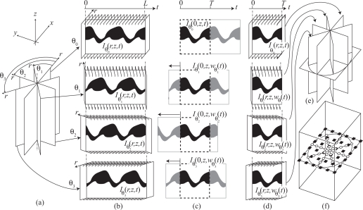
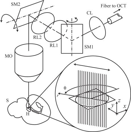
Here, we present a method—sequential turning acquisition and reconstruction (STAR)—for imaging periodically moving structures that does not require measuring an additional gating signal yet still overcomes the error accumulation limitation introduced by gating-free recursive synchronization procedures. Our STAR approach proceeds similarly to nongated approaches where multiple fast images series are consecutively acquired, but instead of considering a set of parallel imaging planes, it involves 2D+T series acquired in imaging planes that share a common axis (Fig. 3(a)). In STAR, all planes share the same common line. This line is chosen, during acquisition, to be of good quality (e.g. in the center of the heart). This geometry is made possible by the fact that traditional OCT data are acquired as a collection of one-dimensional in-depth scans (axial scans or A-scans) serving as single units of information. Two-dimensional images (or B-scans) are obtained by laterally moving the OCT beam with two galvanometer-controlled mirrors (see Fig. 2). Since the direction of the A-scans is fixed along the z-direction the B-scan planes are always vertical. However, the user can freely adjust the orientation and lateral position of the plane by controlling the mirrors’ oscillations.
Fig. 3.
Sequential turning acquisition and reconstruction (STAR) method. (a) Image sequences are acquired (without gating) along planes oriented radially. Note that all sequences share a common line, the rotation axis, where the radial planes intersect. (b) Intensity of the central line of slice sequences versus time (kymograph) acquired sequentially at different orientations θi. (c) Synchronization of the sequences, with respect to the sequences θ0 is carried out by time-warping the kymographs. (d) The warping function obtained from the intensity values on the common axis is then applied to the other pixels in the sequences, resulting in synchronized radial sequences that cover one (or possibly more) period(s). (e) the synchronized sequences can either be visualized as cutting planes or (f) interpolated onto a Cartesian grid for volume rendering.
Fig. 2.
X–Y scanner allows recording vertical planes arbitrarily rotated around a vertical axis. The signal emanating from the fiber of one arm of an OCT system is sent through an X–Y scanner (consisting of two scanning mirrors SM1 and SM2 and two relay lenses RL1 and RL2) via a collimating lens lens (CL), into a microscope objective (MO) and to the heart (H) inside the sample (S). The inset shows how one 2D OCT image frame (B-scan) is assembled from a collection of 1D signals (A-scans) that record the scattering within the sample along the vertical direction. The double arrow indicates the scanning motion produced by the galvanometer-mounted mirrors that can oscillate around a fixed axis.
Also, since the central line of all 2D+T time-sequences represents measurements taken over the same physical line (the rotation axis), the central 1D+T signal from each sequence can be used for synchronization. The central lines serve as intrinsic temporal gating signals for post-acquisition synchronization. After the synchronization, the data are transformed from cylindrical into orthogonal coordinates to reveal the 3D+T representation of the periodically moving structure.
Our method bears some similarity with a recently presented method by Happel et al. [24] for OCT of chicken embryos. There, images are acquired in a geometry identical to ours (with a common A-scan) after which each frame in a sequence at a given angle is assigned a new time stamp (based on an algorithm that assumes perfect, yet unknown, periodicity in the sequence). Although this algorithm can handle variations in the heart frequency that occur in between angles, it does so by reshuffling the images, producing a new sequence in which images from multiple heartbeats are interleaved. Our reconstruction algorithm differs in that it applies a nonuniform, elastic registration that preserves the order of the frames and allows reconstruction even in the presence of slight, local variations in the heartbeat that occur during acquisition at a single angle. By preserving the sequence order, our algorithm produces reconstructions in which aperiodic motion features within a sequence at a given angle, such as moving red blood cells, could be analyzed to infer lateral blood flow velocities within one plane (e.g. via block matching or optical flow techniques).
In Section 2 we formally introduce the acquisition and reconstruction method. Then, in Section 3, we present validation reconstructions obtained with the parallel-slice and proposed STAR method. We also present experimental results from data collected in the beating heart of an embryonic rat.
2. Method
We consider a dynamic, three-dimensional object, whose measured intensity I(x,y,z,t) is periodic, translating to
| (1) |
where T is the period of the cardiac cycle. Since, in practice, signals are never perfectly periodic, we relax this constraint by assuming that, given a reference period T, the length of other periods may only vary by an estimated percentage α of the reference period such that the minimal and maximal lengths of the cycles are Tmin = (1 – α)T and Tmax = (1 + α)T, respectively.
For cardiac imaging in live embryos, intensity is varying rapidly with time (the embryonic heart rate is approximately 2–3 beats per second) and instantaneous acquisition of three-dimensional data in the spatial dimension (corresponding to ideal sampling at a fixed point in time) is technologically challenging. Rather, data along the spatial dimensions are acquired sequentially to build a multi-dimensional image. Images are built by sequentially scanning individual voxels, lines, or, at best, full planes. Here we assume that a 2D plane (B-scan) can be acquired in a single shot with high repetition rate. Specifically, we assume that the imaging system allows for instantaneous acquisition of a full two-dimensional plane parametrized by the coordinates (r,z), defined by a rotation of angle θ ∈ [0,π) around the z-axis of the plane y = 0 (see Fig. 3 (a)). We consider the set of measurements
| (2) |
for rotation angles θ ∈ [0,π), radial coordinates r ∈ [−rM, rM], and axial coordinates z ∈ [0,zm], over time t ∈ [0,L), each sequence being triggered at a time offset tθ. This set of measurements corresponds to the sequential acquisition of 2D+T image sequences of duration L and is schematically depicted in Fig. 3(b). The acquisition of these sequences is not triggered at any particular time in the cardiac cycle (non-gated imaging), but to ensure that at least one complete cycle of the heartbeat (starting at any arbitrary time in the cycle) can be extracted from each sequence, the acquired sequences must be of length L ≥ 2Tmax, that is, they must be twice the duration of the longest heartbeat period estimate.
These sequences are acquired in a radial, star-like pattern, with all planes intersecting at and sharing the z-axis (see Fig 3 (a)). The first period of the sequence—I0(r,z,t) for t = [0,T) (in the plane y = 0)—is considered the reference and the other sequences are synchronized to it. The nonrigid synchronization problem is equivalent to finding a set of angle-dependent warping functions wθ(t) for all rotation angles θ ∈ [0,π) such as to minimize, along the shared z-axis (that is, the axis defined by r = 0, see Fig. 3(c)), the functional
| (3) |
The first double integral over time and the axial direction z compares a temporally warped sequence (a sequence whose temporal axis is deformed) Iθ(0,z,w(t)) with the template I0(0,z,t), while the second integral keeps the extent of this deformation in check by penalizing warping functions w(t) that stretch or compress the time axis. These two contributions to the cost function are balanced by the parameter 0 ≤ λ < 1 to favor either good matching of the warped and reference sequences (λ = 0) or the temporal integrity of the warped sequence (λ → 1). We note that the warping functions w are in the set 𝓜 = {w ∈ C1([0,T))|0 ≤ w(t) < L and w(t1) < w(t2),t1 < t2} of continuous, non-negative, and strictly increasing functions bounded by L and defined over the interval [0,T). We then determine a warping function that minimizes the cost function. This minimization is carried out using a previously described dynamic programming algorithm, which traces a minimum-cost path in a two-dimensional similarity graph [25]. For each angle, the optimal warping function produced by this algorithm is wθ ∈ {w ∈ 𝓜|Q{w} = minw′∈𝓜 Qθ {w′}}. For example, if λ = 1, the matching is rigid and warping functions are of the form w(t) = t0 + t, a uniform offset in time. As λ < 1 decreases, the resulting warping functions can become non-linear to better match the data.
Once the warping functions are determined, we compute time-interpolated series (according to the temporal warping functions wθ) for the measured intensity series Iθ for each angle θ (see Fig. 3(d))
| (4) |
Although the synchronized series could be visualized per se (see Figs. 3(e) and 6(a)), it is usually desirable to have a volumetric representation of the data in Cartesian coordinates (see Fig. 3(f)). The final step of the reconstruction therefore consists in converting, at each time point t ∈ [0,T) from a cylindrical geometry (θ,r,z) to a Cartesian grid (x,y,z). Given samples for uniformly spaced angles θi = iΔθ, 0 ≤ i < Nθ and uniformly-spaced radial coordinates rj = −rM + jΔr, 0 ≤ j < Nr (where Δθ = π/Nθ and Δr = 2rM/(Nr − 1) are the angular and radial spacings, respectively), we can define a cubic spline interpolating function
| (5) |
where the centered cubic B-spline function β3 is defined as the 4-fold convolution of β0, the indicator function over the interval [−1/2,1/2],
| (6) |
and where the B-spline coefficients ci,j(z,t) in the expansion (5) are obtained by recursive filtering [26] such that the interpolating function interpolates the data at the sample points (θi, rj)
| (7) |
Fig. 6.
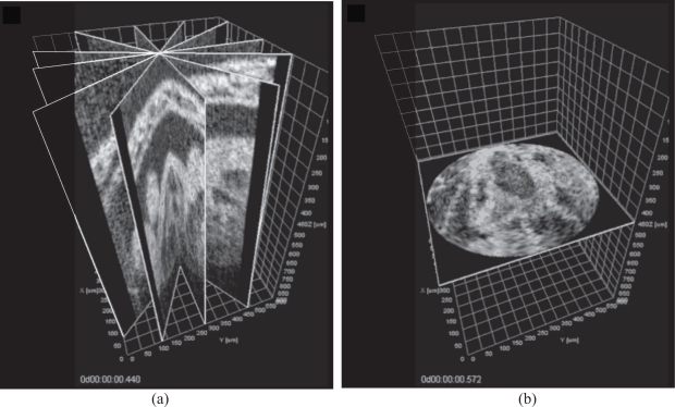
Images of the beating embryonic rat heart at 10.5 days of gestation cultured on the imaging stage obtained via Sequential Turning Acquisition and Reconstruction (STAR). (a) Representative cross-sections through the synchronized reconstruction demonstrating the positions of the imaging planes (6 out of 60 angles). (b) XY cross-section of STAR data after polar-to-Cartesian interpolation. See also Media 2 (22.5MB, MOV) , Media 3 (2.6MB, MOV) , and Media 4 (2.4MB, MOV) .
Finally, the recovered intensity Ir on a Cartesian grid is given by
| (8) |
where the Cartesian to polar coordinate transform is given by
| (9) |
where −π < atan2(y,x) = Prarg(x + iy) ≤ π is the principal argument of the complex number x + iy, which is restricted to the interval (−π,π].
3. Results
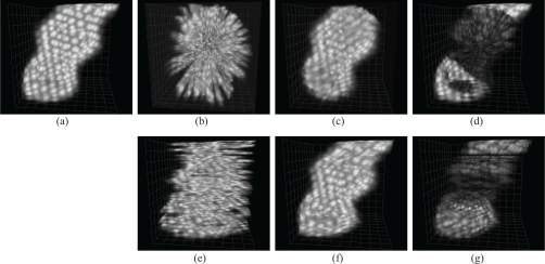
To evaluate the reconstruction accuracy of STAR and illustrate the advantages over sequential parallel-slice acquisition and reconstruction, we carried out a simulation experiment with a synthetic, periodically deformed heart tube phantom, presented in [8] and shown in Fig4(a). Briefly, the intensity of a static tube is defined for any real value of x, y, and z in three-space by a parametric analytic equation. To generate intensity volumes over time, an affine transform of the spatial coordinates at which the intensity is to be evaluated is carried out, and the heart-tube function is evaluated at the transformed coordinates. The affine transform is defined by a matrix whose coefficients are given by a weighted sum of sinusoidal and cosinusoidal functions at harmonic frequencies. Here, acquisition of data was simulated either by evaluating the phantom values sequentially for different y-sections (see Fig. 4(d)) or by acquiring sections in a radial geometry (Fig. 4b) to match our proposed acquisition conditions. For each time-series, we introduced a random time-shift (uniform distribution in [−T,T]), similarly to the approach in [8].
Fig. 4.
Still of heart phantom (a) Reference image of synthetically generated heart phantom. (b–d) STAR (b) sequentially acquired slices in radial geometry (rotation axis is perpendicular to page), before alignment (c) STAR reconstructed volume (d) absolute difference between reference and reconstruction (e–g) Parallel geometry (e) sequentially acquired slices in parallel geometry, before alignment (f) post-acquisition aligned reconstruction (g) absolute difference between reference and reconstruction. See also Media 1 (7.7MB, MOV) .
We next reconstructed the data in the STAR and conventional geometries (Fig. 4(c) and (f), respectively). We compared the resulting data volumes with the reference data volumes and computed the absolute difference voxel by voxel resulting in a difference data volume (see Fig. 4(d) and (g) for the difference images corresponding to reconstructions from sequential parallel-section imaging and STAR imaging, respectively).
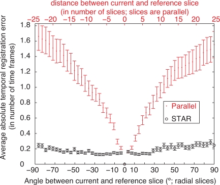
By randomly selecting (following a zero-mean normal distribution with σ = 0.1) the weights of sine and cosine functions up to the third harmonic (higher harmonics were set to zero), we generated 100 dynamic reference phantoms as well as corresponding sequential parallel-slice and radial measurement series (50 slices in each case), introducing random time-shifts (following a uniform distribution in [−T,T]) for each section. We then ran our algorithms to synchronize the slices and recover volumes for both acquisition geometries. Since the ground-truth shifts were known, we could accurately estimate reconstruction errors: for each synchronized slice time series, we compared the local time-shifts of the frames produced by the warping functions, and subtracted them from the actual shift introduced during the simulation. We then calculated the mean of the absolute value of the errors of all frames in a given section. Figure 5 shows the average synchronization error for image series at a given depth or orientation (computed over the 100 simulated experiments) as a function of distance from the reference slice (in the case where volumes were reconstructed from parallel slices) and angular distance from the reference slice (in the case of STAR).
Fig. 5.
Synchronization error does not accumulate with STAR reconstruction (which synchronizes radial slices that all share common line to the same line in the reference slice) unlike methods that sequentially record parallel-slices at increasing distance (on both sides) of a reference slice then proceed recursively to synchronize the slices. Each point corresponds to the absolute value of the synchronization error for one image sequence, obtained by averaging the absolute errors at all time-points. Error bars correspond to the standard deviation over 100 simulations, divided by .
In the case of recursive reconstruction, the average time-synchronization error increases as the distance to the reference slice increases. This is visible in Figure 5. Visually, this translates to high difference images toward the top and bottom in Fig. 4(g)). This degradation can be explained by the fact that the parallel section algorithm proceeds recursively: with 50 slices to align, the error propagates (the central slice was used as a reference).
Conversely, for the STAR reconstruction the synchronization proceeds non-recursively (only the central portion of each slice is aligned to the central portion of the reference slice) the error remains in check (Fig. 5), even for large number of slices and for angles very different from that of the reference. Large differences visible in the STAR reconstruction error image near the top and bottom of the tube (see Fig. 4(d)) are due to the fact that the reconstruction is limited to a cylinder. Within the cylinder, the difference image does not show a systematic error. Rather, remaining visible errors are mostly due to the lower sampling step away from the center in the STAR geometry.
To evaluate the feasibility of our method in practice, we acquired image sequences of a live 10.5 day rat embryo using a swept-source OCT (SS-OCT) system as described previously in [27] (procedures were approved by the Animal Care and Use Committee of the University of Houston). Briefly, the experimental system was customized from the Thorlabs SL1325-P16. It utilizes a broadband swept-source laser with a central wavelength of λ0 = 1325 nm and a bandwidth of Δλ = 110 nm; output power is P = 12 mW; the A-line scanning frequency was 16 kHz. An interferogram is detected by a balanced-receiver configuration that reduces source intensity noise as well as autocorrelation noise from the sample Thorlabs, PDB140C and is digitized using a 14-bit digitizer. A Mach-Zehnder interferometer MZI-based optical frequency clock is used to calibrate the OCT interference signals from the optical time-delay domain in the frequency domain before application of fast Fourier transform FFT algorithms. An FFT is used to reconstruct an in-depth profile A-scan of OCT intensity from a single scan over the operating wavelength range. By 2-D mechanical scanning over the area of up to 10 ×10 mm, the 3-D structure of the embryo can be revealed.
Each time lapse consisted of 200 frames of 256 × 512 pixels (512 pixels per A-scan) acquired at 51 frames per second. The whole data set consisted of 60 image sequences; the angle between the neighboring time lapses was set to 3°. The central line (axis of the imaging plane rotation) was positioned over the highly moving structure to ensure strong reference signal for synchronization. We were able to successfully reconstruct the dynamics of the beating heart in the embryo using the proposed algorithm (Fig. 6 and Media 2 (22.5MB, MOV) , Media 3 (2.6MB, MOV) , and Media 4 (2.4MB, MOV) ).
4. Conclusion
In this paper, we have provided an acquisition and reconstruction algorithm for imaging of dynamic cardio-vascular structures whose motion is cyclical. The STAR algorithm, relies on the intrinsic signal provided by an axis of data common to all slices. Our algorithm has several advantages, in particular over previously proposed non-gated imaging and reconstruction algorithms in which data are acquired over parallel sections instead of radial sections. Our method achieves accurate reconstructions without requiring any additional hardware for acquiring a gating signal. Unlike existing nongated synchronization approaches where slices are synchronized to neighboring slices and errors may accumulate with each round of synchronization, in the STAR method, there is no accumulation of the error since all slices are synchronized to the same signal. If the sample drifts during acquisition, this becomes obvious after reconstruction, since after 180° rotation, the imaging plane is a mirror-image of the initial position. We demonstrated the method’s improved accuracy on simulated data and its practical applicability for in vivo imaging of embryonic rats.
Since sampling occurs in polar coordinates, the spatial resolution is non-uniform: it is finer towards the axis of rotation and coarser as the radial distance increases. In our experiment, where the extent of the OCT scan is 400 μm (and represents the size of a 10.5 dpc embryonic rat heart) and the imaging plane is rotated by 3° for each time series, the distance between neighboring slices at the radially most distant border is about 10 μm, which is similar to the step used for parallel-slice imaging approaches.
Use of an elastic synchronization method that does not assume the interval between heartbeats to remain constant ensures robustness to slight variations in heartbeat period, which we previously showed to be beneficial in the case of parallel-slice imaging [9].
Our method is general and could be applied for structural or any other (e.g. Doppler) imaging of periodically moving structures with optical coherence tomography, or other modalities that allow acquiring images according to the proposed geometry.
Acknowledgments
This research was supported by NIH HL077187, HL095586, and T32HL007676, AHA 10SDG3830006 (I. V. L.), and a Hellman Faculty Fellowship (M.L).
References and links
- 1.Yelbuz T., Choma M., Thrane L., Kirby M., Izatt J., “A new high-resolution imaging technology to study cardiac development in chick embryos,” Circulation 106, 2771–2774 (2002). 10.1161/01.CIR.0000042672.51054.7B [DOI] [PubMed] [Google Scholar]
- 2.Larina I. V., Larin K. V., Justice M. J., Dickinson M. E., “Optical coherence tomography for live imaging of mammalian development,” Curr. Opin. Genet. Dev. 21, 579–84 (2011). 10.1016/j.gde.2011.09.004 [DOI] [PMC free article] [PubMed] [Google Scholar]
- 3.Larina I., Sudheendran N., Ghosn M., Jiang J., Cable A., Larin K., Dickinson M., “Live imaging of blood flow in mammalian embryos using Doppler swept-source optical coherence tomography,” J. Biomed. Opt. 13, 060506 (2008). 10.1117/1.3046716 [DOI] [PubMed] [Google Scholar]
- 4.Larina I., Ivers S., Syed S., Dickinson M., Larin K., “Hemodynamic measurements from individual blood cells in early mammalian embryos with Doppler swept source OCT,” Opt. Lett. 34, 986–8 (2009). 10.1364/OL.34.000986 [DOI] [PMC free article] [PubMed] [Google Scholar]
- 5.Larin K. V., Larina I. V., Liebling M., Dickinson M. E., “Live imaging of early developmental processes in mammalian embryos with optical coherence tomography,” J. Innovative Opt. Health Sci. 2, 253–259 (2009). 10.1142/S1793545809000619 [DOI] [PMC free article] [PubMed] [Google Scholar]
- 6.Gargesha M., Jenkins M. W., Wilson D. L., Rollins A. M., “High temporal resolution OCT using image-based retrospective gating,” Opt. Express 17, 10786–10799 (2009). 10.1364/OE.17.010786 [DOI] [PMC free article] [PubMed] [Google Scholar]
- 7.Liu A., Wang R., Thornburg K., Rugonyi S., “Efficient postacquisition synchronization of 4-D nongated cardiac images obtained from optical coherence tomography: application to 4-D reconstruction of the chick embryonic heart,” J. Biomed. Opt. 14, 044020 (2009). 10.1117/1.3184462 [DOI] [PubMed] [Google Scholar]
- 8.Liebling M., Forouhar A. S., Gharib M., Fraser S. E., Dickinson M. E., “Four-dimensional cardiac imaging in living embryos via postacquisition synchronization of nongated slice sequences,” J. Biomed. Opt. 10, 054001 (2005). 10.1117/1.2061567 [DOI] [PubMed] [Google Scholar]
- 9.Liebling M., Forouhar A. S., Wolleschensky R., Zimmerman B., Ankerhold R., Fraser S. E., Gharib M., Dickinson M. E., “Rapid three-dimensional imaging and analysis of the beating embryonic heart reveals functional changes during development,” Dev. Dynam. 235, 2940–2948 (2006). 10.1002/dvdy.20926 [DOI] [PubMed] [Google Scholar]
- 10.Skare S., Andersson J. L. R., “On the effects of gating in diffusion imaging of the brain using single shot EPI,” Magn. Resonance Imaging 19, 1125–1128 (2001). 10.1016/S0730-725X(01)00415-5 [DOI] [PubMed] [Google Scholar]
- 11.Kachelrieß M., Sennst D. A., Maxlmoser W., Kalender W. A., “Kymogram detection and kymogram-correlated image reconstruction from subsecond spiral computed tomography scans of the heart,” Med. Phys. 29, 1489–1503 (2002). 10.1118/1.1487861 [DOI] [PubMed] [Google Scholar]
- 12.Grass M., Manzke R., Nielsen T., Koken P., Proksa R., Natanzon M., Shechter G., “Helical cardiac cone beam reconstruction using retrospective ECG gating,” Phys. Med. Biol. 48, 3069–3084 (2003). 10.1088/0031-9155/48/18/308 [DOI] [PubMed] [Google Scholar]
- 13.Markl M., Chan F. P., Alley M. T., Wedding K. L., Draney M. T., Elkins C. J., Parker D. W., Wicker R., Taylor C. A., Herfkens R. J., Pelc N. J., “Time-resolved three-dimensional phase-contrast MRI,” J. Magn. Resonance Imaging 17, 499–506 (2003). 10.1002/jmri.10272 [DOI] [PubMed] [Google Scholar]
- 14.Jerecic R., Bock M., Nielles-Vallespin S., Wacker C., Bauer W., Schad L. R., “ECG-gated Na-23-MRI of the human heart using a 3D-radial projection technique with ultra-short echo times,” Magn. Resonance Mater. Phys. Biol. Med. 16, 297–302 (2004). 10.1007/s10334-004-0038-8 [DOI] [PubMed] [Google Scholar]
- 15.Jenkins M., Rothenberg F., Roy D., Nikolski V., Hu Z., Watanabe M., Wilson D., Efimov I., Rollins A., “4D embryonic cardiography using gated optical coherence tomography,” Opt. Express 14, 736–748 (2006). 10.1364/OPEX.14.000736 [DOI] [PubMed] [Google Scholar]
- 16.Mariampillai A., Standish B. A., Munce N. R., Randall C., Liu G., Jiang J. Y., Cable A. E., Vitkin I. A., Yang V. X. D., “Doppler optical cardiogram gated 2D color flow imaging at 1000 fps and 4D in vivo visualization of embryonic heart at 45 fps on a swept source OCT system,” Opt. Express 15, 1627–1638 (2007). 10.1364/OE.15.001627 [DOI] [PubMed] [Google Scholar]
- 17.Dinkel J., Bartling S. H., Kuntz J., Grasruck M., Kopp-Schneider A., Iwasaki M., Dimmeler S., Gupta R., Semmler W., Kauczor H.-U., Kiessling F., “Intrinsic gating for small-animal computed tomography a robust ECG-less paradigm for deriving cardiac phase information and functional imaging,” Circulat. Cardiovasc. Imaging. 1, 235–243 (2008). 10.1161/CIRCIMAGING.108.784702 [DOI] [PubMed] [Google Scholar]
- 18.Treece G. M., Prager R. W., Gee A. H., Cash C. J. C., Berman L., “Grey-scale gating for freehand 3D ultrasound,” in 2002. IEEE International Symposium on Biomedical Imaging, 2002. Proceedings (IEEE, 2002), pp. 993–996 [Google Scholar]
- 19.de Winter S. A., Hamers R., Degertekin M., Tanabe K., Lemos P. A., Serruys P. W., Roelandt J. R. T. C., Bruining N., “Retrospective image-based gating of intracoronary ultrasound images for improved quantitative analysis: the intelligate method,” Catheterizat. Cardiovasc. Intervent. 61, 84–94 (2004). 10.1002/ccd.10693 [DOI] [PubMed] [Google Scholar]
- 20.Spraggins T. A., “Wireless retrospective gating—application to cine cardiac imaging,” Magn. Resonance Imaging 8, 675–681 (1990). 10.1016/0730-725X(90)90001-I [DOI] [PubMed] [Google Scholar]
- 21.Thompson R. B., McVeigh E. R., “Flow-gated phase-contrast MRI using radial acquisitions,” Magn. Resonance Med. 52, 598–604 (2004). 10.1002/mrm.20187 [DOI] [PMC free article] [PubMed] [Google Scholar]
- 22.Larson A. C., White R. D., Laub G., McVeigh E. R., Li D. B., Simonetti O. P., “Self-gated cardiac cine MRI,” Magn. Resonance Med. 51, 93–102 (2004). 10.1002/mrm.10664 [DOI] [PMC free article] [PubMed] [Google Scholar]
- 23.Crowe M. E., Larson A. C., Zhang Q., Carr J., White R. D., Li D. B., Simonetti O. P., “Automated rectilinear self-gated cardiac cine imaging,” Magn. Resonance Med. 52, 782–788 (2004). 10.1002/mrm.20212 [DOI] [PubMed] [Google Scholar]
- 24.Happel C., Thommes J., Thrane L., Maenner J., Ortmaier T., Heimann B., Yelbuz T., “Rotationally acquired four-dimensional optical coherence tomography of embryonic chick hearts using retrospective gating on the common central A-scan,” J. Biomed. Opt. 16, 096007 (2011). 10.1117/1.3622491 [DOI] [PMC free article] [PubMed] [Google Scholar]
- 25.Liebling M., Vermot J., Forouhar A., Gharib M., Dickinson M., Fraser S., “Nonuniform temporal alignment of slice sequences for four-dimensional imaging of cyclically deforming embryonic structures,” in 3rd IEEE International Symposium on Biomedical Imaging: Nano to Macro, 2006 (2006), pp. 1156–1159 10.1109/ISBI.2006.1625128 [DOI] [Google Scholar]
- 26.Unser M., “Splines: a perfect fit for signal processing and image processing,” IEEE Signal Process. Mag. 16, 22–38 (1999). 10.1109/79.799930 [DOI] [Google Scholar]
- 27.Larina I. V., Furushima K., Dickinson M. E., Behringer R. R., Larin K. V., “Live imaging of rat embryos with doppler swept-source optical coherence tomography,” J. Biomed. Opt. 14, 050506 (2009). 10.1117/1.3241044 [DOI] [PMC free article] [PubMed] [Google Scholar]


