Abstract
High sensing resolution is required in sensing of surgical instrument motion in micromanipulation tasks. Accelerometers can be employed to sense physiological motion of the instrument during micromanipulation. Various configurations of accelerometer placement had been introduced in the past to sense motion of a rigid-body such as a surgical instrument. Placement (location and orientation) of accelerometers fixed in the instrument plays a significant role in achieving high sensing resolution. However, there is no literature or work on the effect of placement of accelerometers on sensing resolution. In this paper, an approach of placement of accelerometers within an available space to obtain highest possible sensing resolution in sensing of rigid-body motion in micromanipulation tasks is proposed. Superiority of the proposed placement approach is shown in sensing of a microsurgical instrument angular motion by comparing sensing resolutions achieved as a result of employing the configuration following the proposed approach and the existing configurations. Apart from achieving high sensing resolution, and design simplicity, the proposed placement approach also provides flexibility in placing accelerometers; hence it is especially useful in applications with limited available space to mount accelerometers.
Keywords: Accelerometer placement, micromanipulation, sensing resolution, rigid-body motion, angular velocity
1. Introduction
To improve micromanipulation accuracy of surgeons, a number of engineered devices or systems have been or are being developed. These include telerobotics systems [1][2][3], steady-hand robotics systems [4], and hand-held active tremor compensation instruments [5][6][7][8] which have been under research and development for a few years. The instruments have three main parts: sensing, filtering or processing of sensed data, and manipulation. Accurate sensing of the tremor motion of the surgical tool attached to the distal end of the instrument is important for effective compensation for the tremor [9][10].
In the instruments described in [6][7][8], motion of the surgical tool is calculated by rigid-body kinematics using micromachined inertial sensors. Inertial sensors are employed because they do not have line-of-sight problem which exists in other sensing modalities such as optical-based sensing, ultrasonic-based sensing, etc. Micromachined type inertial sensors are chosen due to their compactness in size, light in weight, and cheapness. In earlier instrument prototypes [6][7], micromachined accelerometers and gyroscopes are used for sensing three degrees-of-freedom (DOF) translational motion and three DOF angular motion respectively. In the successive instrument [8][11], only accelerometers are employed since it is found out that angular sensing resolution provided by micromachined gyros is poorer than that derived from micromachined accelerometers for a given space inside the instrument [11][12]. However, it is stated in [8] that sensing resolution of the hand-held instrument is still poor to have effective compensation. This might have resulted from non-optimal placement of accelerometers in the instrument. Therefore, the authors performed literature review on angular motion sensing using only accelerometers to find accelerometer placement which provides better sensing resolution.
The concept of the viability of the use of linear accelerometers to measure angular motion of a rigid body is introduced in 1965 [13]. A number of researchers contribute towards the improvement of the original concept [14][15]. There seem to be little progress in this area of rigid body motion detection using accelerometers from 1979 until 1994 when an original cube configuration of placement of six accelerometers, the minimum number of accelerometers required to detect six degrees-of-freedom (DOF) motion of a rigid body [16], is introduced by Chen et al. [17]. Several researchers have been working on the improvement of gyro-scope free inertial navigation systems (GF-INS) based on the original cube configuration [18][19][20][21][22]. However, there is little or no literature or research on the effect of accelerometer placement on motion sensing resolution/precision.
The use of the cube configuration is neither feasible nor yields highest possible sensing resolution in some applications such as tremor compensation owing to space constraints: the space available is not in cube shape. In these situations, researchers have to seek for other accelerometer placement configurations within the given space constraints [8][11][23]. The configurations are not optimal in terms of resolution. There are no guidelines or rules from the view point of precision for the general placement configuration of accelerometers to detect six DOF motion of a rigid body. For example, for a given same space available, three different accelerometer placement configurations involving six accelerometers to detect six DOF motion are shown in Figure 1. All the three placement configurations can provide six DOF motion sensing. The configuration on the right is the cube configuration introduced by Chen et al. [17]. However, it is not obvious which one would provide the highest angular sensing resolution.
Figure 1.
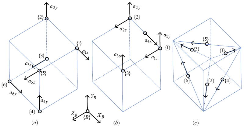
Three different configurations of accelerometer placement within the same space available to detect six DOF motion.
Therefore, it is necessary to find out and propose accelerometer placement configurations to yield high sensing resolution without having to restrict the design to the cube configuration, thereby allowing the highest possible sensing resolution for a given space constraint.
2. Placement of Accelerometers
In this section, propositions for placement of a pair of two accelerometers to detect an angular acceleration component (one DOF angular acceleration) with the highest possible angular acceleration resolution (i.e., the lowest possible angular acceleration sensing noise) in micromanipulation tasks, and proofs of the propositions are described. To detect all the three angular acceleration components, two more pairs of accelerometers can simply be employed. To reduce the number of accelerometers required to a minimum, sensing of the other two components (two DOF angular acceleration) only with three accelerometers is described. To minimize sensing noise of these two components, constrained optimization using the space constraints is proposed. Placement configurations for sensing three DOF angular motion, and six DOF motion are then presented.
2.1. Propositions for one DOF angular acceleration
Only a pair of two accelerometers is required by the proposed placement to sense a particular angular acceleration component. The two accelerometers must be placed so that their sensing directions are the same (i.e., their sensing axes are parallel to each other). The propositions are as follows.
Proposition (i): Separation distance along a principal axis (i.e., perpendicular distance) between the two sensing axes of the accelerometers must be as large as possible. (d1 in Figure 2 represents the separation distance) A square box is added in the figures for better visualization of placement of accelerometers, and representation of space available.
Proposition (ii): The two accelerometers must be placed in a way that their sensing axes form a plane perpendicular to the principal axis about which the angular acceleration is calculated. The line which passes the two accelerometers should be perpendicular to the sensing axes to keep the negligible error minimum. Even if it is not perpendicular, the added error can still be negligible. The accelerometers shown in Figure 2 (b) form a perpendicular plane, but the line passing through them is not perpendicular to their sensing axes. The accelerometers shown in Figure 2 (c) do not form a perpendicular plane and hence the placement does not satisfy the proposition ii. (d2 in Figure 2 represents an offset distance which prevents the accelerometer axes from forming a perpendicular plane.)
Figure 2.
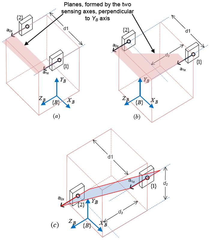
Illustration of the separation distance (d1), and offset distance (d2) between the two sensing axes. Accelerometers, a1z and a2z, used to sense angular acceleration about YB axis, form perpendicular planes in (a), and (b), but not in (c).
The placement that does not satisfy (ii) will require knowledge of another angular acceleration component in the calculation of a particular angular acceleration component resulting in more noise in the angular acceleration, or requiring more accelerometers. The amount of extra noise is dependent on the amount of the offset.
2.1.1 Proof of propositions
The total accelerations, Ai, each accelerometer at {i} senses include the inertial acceleration of the body, AIN, the gravity, G, and the rotation-induced accelerations: the centripetal acceleration, Ai/C, and the tangential acceleration, Ai/T.
| 1 |
| 2 |
where all the variables are relative to the body frame {B}, is the angular velocity vector, R is the vector from the unknown instantaneous center of rotation to the point of sensing, and is angular acceleration vector. The symbol×represents a cross-product operation.
Taking the difference between the accelerations readings at {i} and {j}, the non-rotation induced acceleration components AIN and G are eliminated, since the linear inertial acceleration of the body and the gravity should be identical at different locations,
| 3 |
where , is position vector from {i} to {j}.
Negligible Centripetal Acceleration
In this section, it is described that the centripetal acceleration term is negligible with the proposed placement and hence it can be ignored. Expanding (3) into component-form,
| 4 |
Solving the above equation,
| 5 |
It can be seen that as long as accelerometer placement follows the proposition (ii), only two terms consisting of the separation distance exist: one for centripetal acceleration and one for tangential acceleration. For example, accelerometers having sensing direction along X-axis, with separation distance along Z-axis, equation (5) becomes
| (5.a) |
In micromanipulation tasks, angular velocity is relatively very small comparing to angular acceleration. It is described in [24] statistics of angular velocities and angular accelerations of a hand-held instrument during representative micromanipulation tasks. It is reported that average amplitude of angular velocities during micromanipulation tasks is less than 0.05 rad/s while that of angular accelerations is 4 rad/s2.
Substituting these values into centripetal and tangential acceleration terms in equation (5.a), it can be seen that the centripetal term is about 1600 times smaller than the tangential term, and hence the centripetal term can safely be ignored since the error due to ignoring the centripetal term is only 0.06 %. If the line passing through the accelerometers is not perpendicular to their sensing axes due to the offset along the sensing direction (i.e., d3 ≠ 0 as shown in Figure 2(b)), then it can be seen that there are two more terms consisting of the offset distance, d3. For a pair of accelerometers having sensing direction along X-axis, and separation distance along Z-axis, Pijz, equation (5) can be written as
| (5.b) |
Since ωdωd, d = x, y, or z; is so small, the error due to these terms can still be ignored. Therefore, equation (3) can then be written as
| 6 |
In component-form, equation (6) can be written as
| 7 |
Proof of proposition (i)
Let us assume accelerometer placement in Figure 2 (a) or (b). Taking the difference between the accelerations readings at {1} and {2}, and using (7),
| 8 |
where the symbol • denotes undefined quantity.
From the last row in (8), αy is obtained as
| 9 |
It can be written in general for a pair of accelerometers having their sensing direction in r -axis (r = x, y, or z) as
| 10 |
where q = x, y, or z; and q ≠ r.
From (10), root mean square (RMS) noise of angular acceleration component, σαq can be written as
| 11 |
where and are variances of noise outputs of accelerometers. The equation (11) is obtained from (10) using a random variables theorem. The random variables theorem used is stated as follows:
For X1, X2,…, Xn be n mutually independent normal random variables with means μ1, μ2,…, μn and variances respectively, if then the mean of Y, μy, and variance of Y, respectively are
| 12 |
In equation (11), the values of and (accelerometer outputs noises) are fixed. Therefore, to minimize σαq, separation distance (d1) between accelerometer {1} and {2} must be maximized and hence the proposition (i) is proven.
Proof of proposition (ii)
In Figure 2 (c), sensing axes of accelerometers do not form a plane perpendicular to the principal axis about which the angular acceleration is calculated (i.e., P12y ≠ 0). Then, equation (8) becomes
| 13 |
From the last row in (13), angular acceleration about Y-axis, αy, is obtained as
| 14 |
It can be written in general for a pair of accelerometers having their sensing direction in r -axis (r = x, y, or z) as
| 15 |
where q = x, y, or z; s = x, y, or z; and q ≠ r ≠ s.
Its RMS noise becomes
| 16 |
Comparing equation (10) to (15), another angular acceleration component, αs, is required in (15) to get the solution. Consequently, comparing equation (11) to (16), (16) contains one more term which will cause extra noise in the angular acceleration component (αq), if σαs is independent of σ2r and σ1r. If it is independent, then the amount of extra noise depends on the values of d1 and d2, and noise in αs. However, if the two sensing axes of the accelerometers are on the plane, d2 becomes zero and extra noise is eliminated, and hence proposition (ii) is proven.
It can be seen in configurations for sensing three DOF angular motion in section 2.3.1 that calculation of the other two components (two DOF angular acceleration) is independent of accelerometers used for sensing one DOF angular acceleration. That means different pair of accelerometers are used for calculation of required angular acceleration component, (αs, and noise of the required angular acceleration component (σαs) is independent of the two accelerometers (σ2r and σ1r).
2.2. Constrained optimization for sensing two DOF angular acceleration
Sensing of two angular acceleration components can be performed by simply using two more pairs of accelerometers following the propositions, with each pair sensing a different component. However, that is not optimum in terms of the number of accelerometers required. To reduce the number of accelerometers required to a minimum, placement of three accelerometers having the same sensing direction such as the one shown in Figure 3 is proposed. Sensing axes must be perpendicular to the axes about which the angular accelerations are calculated.
Figure 3.
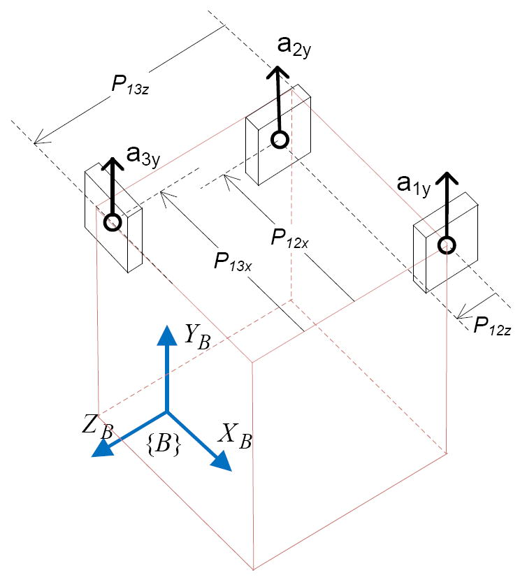
A placement configuration to sense two DOF angular motion (αx and αz)
To achieve the lowest possible noise, constrained optimization based on the space constraints is proposed. For the constrain optimization, angular acceleration components are formulated with parameters, Pijd, representing distances between accelerometers.
Using the equation (7), following equations are obtained.
| 17 |
| 18 |
Solving these two equations, αx and αy are obtained as
| 19 |
| 20 |
RMS noise of αx and αz are written as
| 21 |
| 22 |
As can be seen from (21), and (22), the parameters P12x, P12z, P13x, and P13z determine the noise level. However, it is not obvious to say what values they should be to minimize the noise level, and the values of the parameters are constrained by the available space. Therefore, constrained optimization is proposed. Since minimizing noise level in one component with respect to the parameters might cause the noise level in the other component to increase, vector of the noises of the two components should be used as the objective function for minimization. The noise vector of the two components is
| 23 |
The levels of the noise vector at different values of the parameters can be evaluated, and the minimum values can be found with the corresponding values of the parameters. The ranges of the values of parameters depend on the dimensions of the space available. Once the ranges are defined, an optimization method can be employed.
2.3. Placement configurations for higher DOF motion
In the previous sections, placement configurations for sensing one DOF and two DOF angular accelerations are described. In this section, combination of these configurations for sensing the complete angular acceleration vector (i.e., three DOF angular acceleration), and configurations for sensing six DOF motion are described.
2.3.1 Three DOF angular motion
Three DOF angular motion sensing is achieved by combining placement configurations for sensing one DOF and two DOF angular accelerations. It should be noted that placement design for sensing one DOF angular acceleration is independent of that for sensing two DOF angular acceleration, and vice versa. The only requirement, called “orthogonal requirement”, is that sensing axes of the two pairs of accelerometers must be orthogonal to each other, and separation distance of the pair with two accelerometers must be orthogonal to the sensing axes of the other pair. If the placement does not fulfill the orthogonal requirement, sensing of three DOF angular motion will not be possible since the angular acceleration component sensed by the pair with two accelerometers will be redundant with one of the two angular acceleration components sensed by the pair with three accelerometers. An example of placement configurations fulfilling orthogonal requirement is shown in Figure 4.
Figure 4.
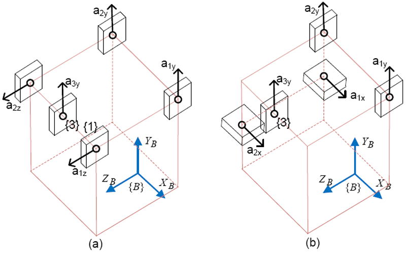
Placement configurations to sense three DOF angular motion
In both configurations shown in Figure 4, placement of the two pairs of accelerometers fulfills the orthogonal requirement. While a1y, a2y, and a3y pair senses two DOF angular acceleration (αx and αz), the other pair of two accelerometers (a1z and a2z pair in Figure 4(a), and a1x and a2x pair in Figure 4 (b)) senses one DOF angular acceleration (αy). Optimal locations of accelerometers a1y, a2y, and a3y can be found by optimization based on the space constraints.
Configurations shown in Figure 5 do not fulfill the orthogonal requirement, and hence they can only sense two DOF angular acceleration (αx and αz in both configurations). To sense three DOF angular acceleration, additional accelerometer(s) would be necessary.
Figure 5.
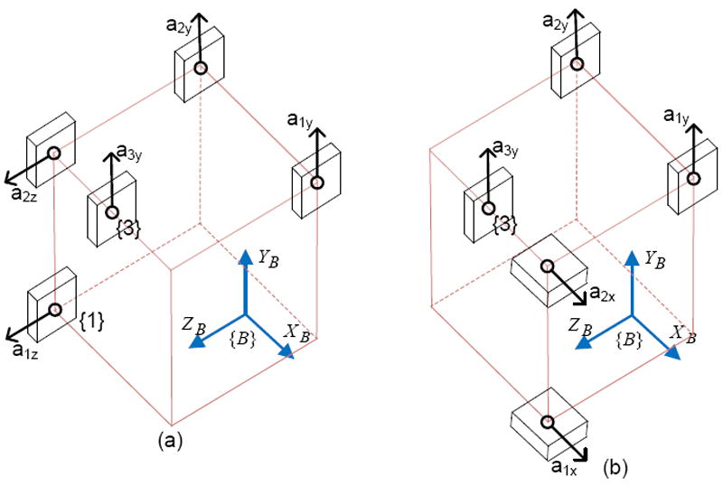
Placement configurations that do not fulfill the orthogonal requirement
Proof of proposition (ii) in the whole system
In section 2.1.1, it has been mentioned that placement of a pair of two accelerometers must form a perpendicular plane. If they do not form a perpendicular plane, another angular acceleration component is required. In this section, it is shown that calculation of this another component required is independent of the two accelerometers pair, and hence extra noise appears due to additional accelerometers.
The configurations in Figure 6 fulfill the orthogonal requirement since the separation distance of the pair with two accelerometers is perpendicular to sensing axes of the other three accelerometers in each configuration. In Figure 6 (a), and (b), the required angular acceleration components are αx and αz, respectively. As in (14), for the pair in Figure 6 (a), angular acceleration component calculated by the pair is written as
| 24 |
Using αx from (19), αy in (24) can be written as
| 25 |
Its RMS noise becomes
| 26 |
Figure 6.
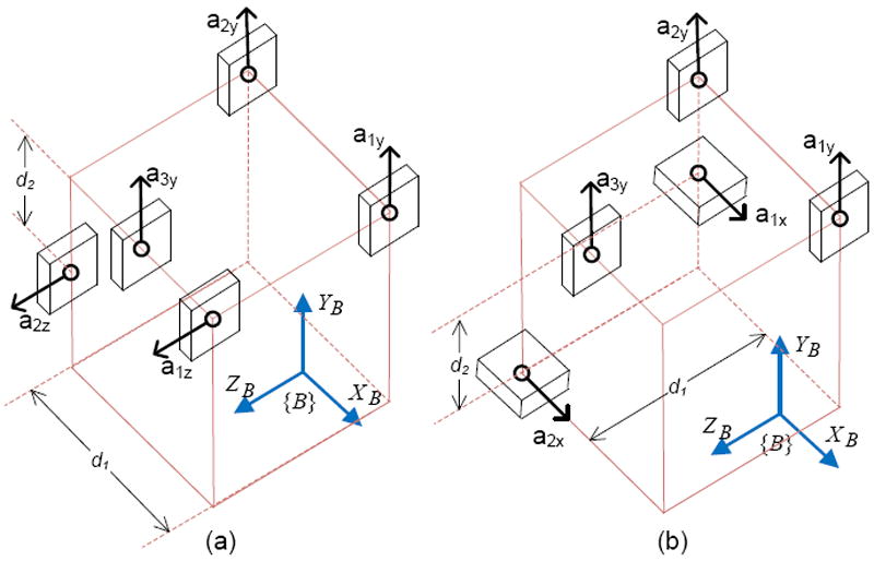
Placement configurations with the pairs with two accelerometers not forming perpendicular planes
It can be seen from (26) that the amount of extra noise depends on the amount of the offset distance d2, and the parameters, Pijd: P12x, P13x, P12z, and P13z, and the noise levels of the three accelerometers. If the offset d2 is zero, then the noise will be minimum regardless of the values of the parameters, and the noise levels.
In general for all the configurations meeting the orthogonal requirement, it can be stated that if sensing axes of the pair with three accelerometers are in the direction of q - axis, then they can provide two angular acceleration components, αr, and αu while the pair with two accelerometers provides αq, where r = x, y, or z; u = x, y, or z; q = x, y, or z; and r ≠ u ≠ q. Therefore, another angular acceleration component required due to the offset is either αr, or αu. In either case, since it is calculated using the three accelerometers, the offset distance, d2, would cause more noise terms appear in the RMS noise equation, meaning RMS noise would be more due to d2.
The proposed placement configurations, which fulfill orthogonal requirement, for sensing three DOF angular acceleration require only five accelerometers. Such placement configurations can also sense two DOF translational motion along the sensing axes of the accelerometers. Therefore, the total number of DOF that the accelerometers can sense is five: three DOF angular motion, and two DOF translational motion.
2.3.2 Six DOF motion
In the previous section, sensing three DOF angular acceleration of a rigid body is described. To know three DOF acceleration at any point on the rigid body, six DOF acceleration information is required. To sense six DOF acceleration, an additional accelerometer having its sensing axis orthogonal to sensing axes of the existing accelerometers is required. Location of the additional accelerometer can be anywhere in the available space. Examples of such placement configurations to sense six DOF motion are shown in Figure 7.
Figure 7.
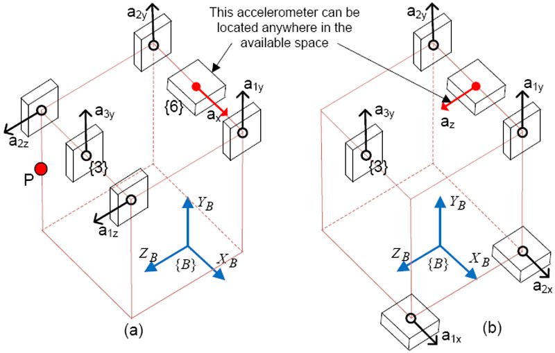
Placement configurations to sense six DOF motion
As in (19) and (20), αx and αz can be written as
| 27 |
| 28 |
The parameters P12x, P13x, P12z, and P13z should be replaced with the values obtained from optimization. As in equation (10) in section 2.1.1, αy can be written in general as
| 29 |
where d = x, or z; D = x, or z; and d ≠ D.
Using all the three angular acceleration components and acceleration in three orthogonal directions, three DOF acceleration at any point on the body can be determined as follows.
Re-arranging (6),
| 30 |
Expanding (30) into component-form,
| 31 |
The equation shows that acceleration in a particular direction at an arbitrary point {j} on a rigid body can be calculated using angular acceleration α and acceleration in the same direction at another point {i} which is a known distance away, Pij. For example, calculation of three DOF acceleration at point P in Figure 7 (a) can be performed as follows.
| 32 |
Substituting (27), (28), and (29) into (32), acceleration components at point P as a function of the accelerometers are obtained as follows
| 33 |
3. Placement of Accelerometers in Hand-held instruments
In this section, advantage of following the proposed approach in placing accelerometers is shown by analyzing and comparing noise levels of angular acceleration obtained from different accelerometer placement configurations in a hand-held microsurgical instrument. For the sake of fair comparison, the same available space inside the instrument is used for different configurations.
3.1 Micron Configuration
Three dual-axis accelerometers (i.e., six single-axis accelerometers) are employed in “Micron”, a hand-held physiological tremor compensation instrument. The placement configuration of accelerometers employed in Micron as well as the space available for mounting accelerometers in the instrument is shown in Figure 8. The placement configuration does not conform to the proposed configurations; hence the angular acceleration noise might not be the least possible.
Figure 8.
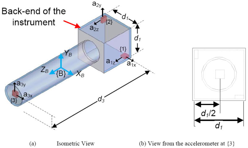
The placement configuration of accelerometers in Micron with d1 = 26 mm, & d3 = 130 mm
The differences between the accelerations readings at {1}, {2} and {3}, are obtained, as in (6), as.
| 35.a |
| 35.b |
| 35.c |
where , i,j = 1, 2, 3, is position vector from {i} to {j}, which are known values from the hardware design and calibrations. Equation (35.a) can be written in component-form as
| 36 |
| 37 |
Equation (35.b) can be written in component-form as
| 38 |
| 39 |
Equation (35.c) can be written in component-form as
| 40 |
| 41 |
Solving equation (37), (39), and (41),
| 42 |
| 43 |
| 44 |
As can be seen from (42-44), calculation of angular acceleration about each axis requires outputs of all the accelerometers, possibly resulting in more noise in the angular accelerations.
3.2 Cube configuration
The cube configuration of accelerometer placement [20] in the instrument is shown in Figure 9. The accelerometers can only be placed either inside the instrument handle or inside the square box at the back-end of the instrument due to the symmetry requirement of the cube configuration. Hence, the cube configuration cannot make full use of the space available. The angular acceleration formulae are extracted from [20] and shown in (45).
| 45 |
Figure 9.
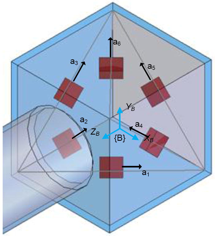
Cube configuration of accelerometer placement in the instrument
3.3 Proposed configuration
The configuration which is based on the proposed placement is shown in Figure 10.
Figure 10.
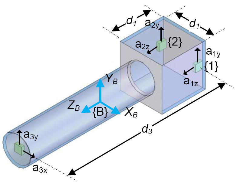
Proposed configuration
As can be seen from the figure, the configuration is similar to the one shown in Figure 7 (a), and consists of a pair of two accelerometers (a2z and a1z) for sensing one angular acceleration component, and another pair of three accelerometers (a1y, a2y, and a3y) for sensing another two components. As can be seen from Figure 10, placement of a2z and a1z pair conforms to the propositions since their separation distance is maximized while their sensing axes form the perpendicular plane. Locations of the three accelerometers are determined by constrained optimization using the space constraint. As in section 2.2, the formulae for the optimization are derived from (7), and are as follows.
| 46 |
| 47 |
For the space available in the instrument, the parameters P12x, P12z, P13x, and P13z are replaced with −kd1, ld1, −0.5d1, and nd3, respectively, where 0 ≤ k ≤ 1; 0 ≤ l ≤ 1; and 0 ≤ n ≤ 1. RMS noise of αx and αz then become as follows
The noise vector of the two components, the objective function, is then obtained as
| 48 |
After the optimization, the minimum noise is found at k = 1, l = 0, and n = 1. The formulae then become
| 49 |
| 50 |
As in (8), angular acceleration about YB axis is written as
| 51 |
3.4 Experiments and Results
A hand-held tremor compensation instrument called “MicronII” having the same dimensions as Micron is developed with the sensing part as shown in Figure 11. The placement of accelerometers in the sensing part is according to proposed configuration shown in Figure 10. Accelerometers employed are dual-axis miniature MEMS accelerometers (ADXL203, Analog Devices, USA).
Figure 11.
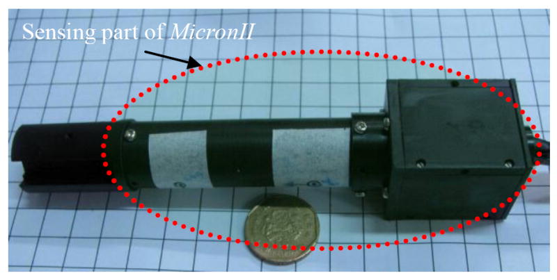
MicronII instrument with the sensing part according to proposed placement of accelerometers
Outputs of the accelerometers placed inside the instrument are obtained and are put in the equations (42-44), (45) and (49-51) to obtain angular accelerations for Micron configuration, cube configuration, and proposed configuration, respectively. Each accelerometer output has RMS noise of approximately 10 mm/s2. Since the instrument is stationary, the ground truth angular acceleration is zero. Therefore, angular accelerations obtained from the equations are due to noise. Angular acceleration noises obtained in different configurations are shown in Figure 12, Figure 13, and Figure 14.
Figure 12.
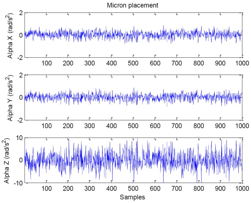
Angular acceleration noise in Micron configuration
Figure 13.
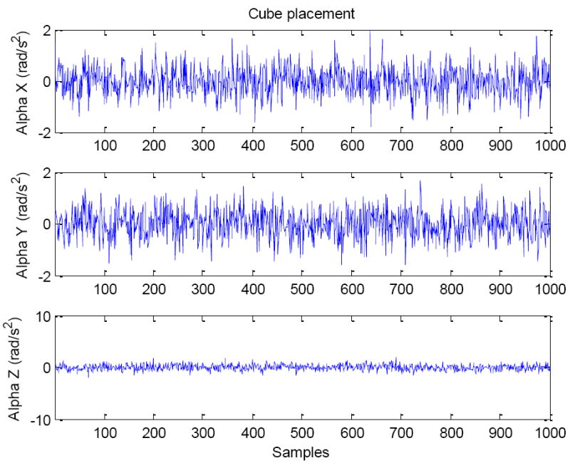
Angular acceleration noise in Cube configuration
Figure 14.
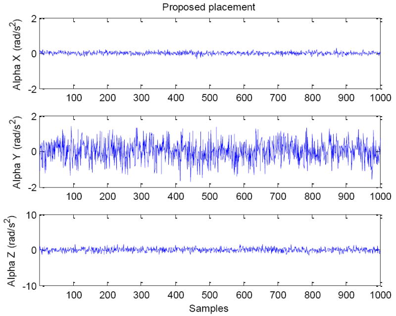
Angular acceleration noise in proposed configuration
Table 1 shows comparison of RMS noise of angular acceleration of all the configurations. Table 2 shows amount of angular acceleration noise reduction by the proposed configuration. The calculation of amount of noise reduction comparing to Micron and Cube configurations is based on the following formula.
, and
where NP, NM, and NC are RMS of noise in angular acceleration vector in proposed configuration, Micron configuration, and Cube configuration, respectively.
Table 1.
Comparison of RMS noise of angular acceleration of all the configurations
| RMS Noise of Angular Acceleration | Micron Configuration | Cube Configuration | Proposed Configuration |
|---|---|---|---|
| αx (rad/s2) | 0.28 | 0.54 | 0.09 |
| αy (rad/s2) | 0.28 | 0.54 | 0.54 |
| αz (rad/s2) | 2.83 | 0.54 | 0.54 |
| Vector α (rad/s2) | 2.86 | 0.94 | 0.78 |
Table 2.
Angular acceleration noise reduction by proposed configuration
| Noise reduction | Compared with Micron configuration | Compared with Cube configuration | |
|---|---|---|---|
|
|
73 | 17 |
To confirm correctness of the derivation and hence the angular acceleration formulae described in (49-51), an experiment is conducted. The instrument (MicronII) is placed on a one-degree of freedom rotating arm as shown in Figure 15. The distal end of the sensing part is attached with a non-reflective black color rod. The tip of the rod is attached with a reflective ball whose location is sensed using a micro motion sensing system, M2S2 [25][26][27]. The location of the ball with respect to the center of rotation of the rotating arm is known.
Figure 15.
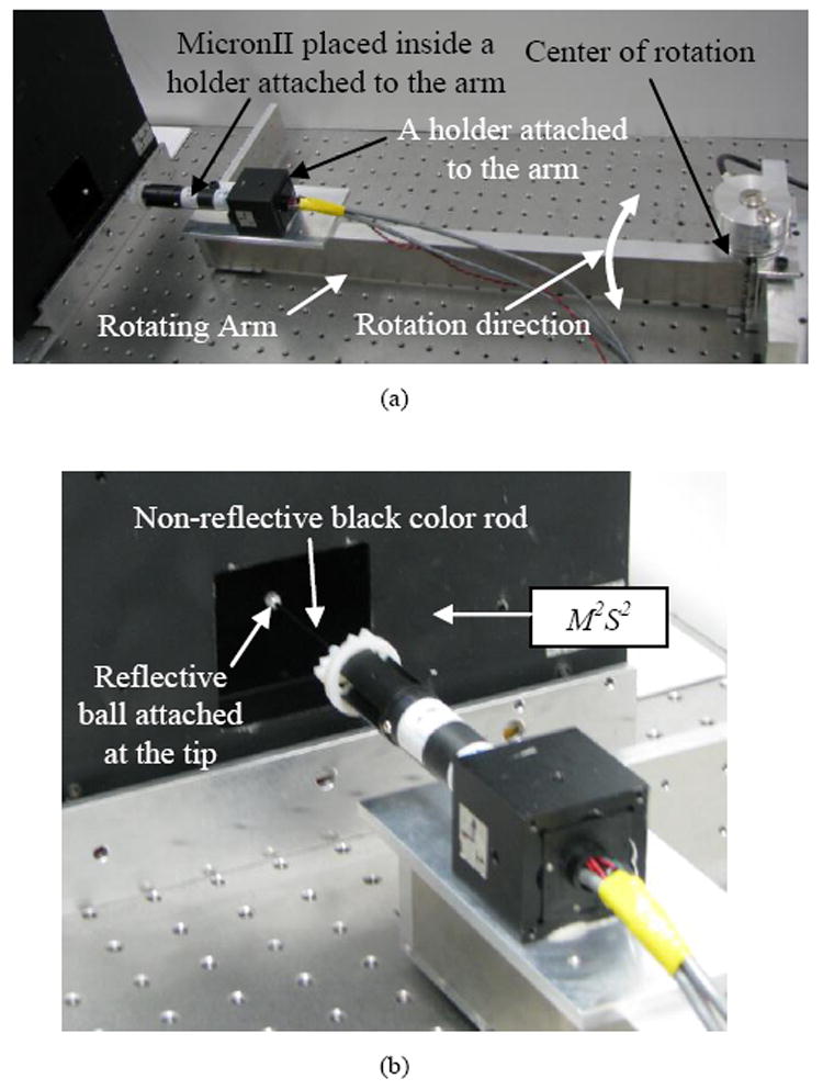
A photo of (a) the MicronII instrument attached to the rotating arm, and (b) close-up view of the instrument tip placed near to the workspace of M2S2
Rotational motion of the instrument is produced by shaking the rotating arm horizontally back-and-forth. The rotational acceleration of the instrument is calculated from the M2S2 measured positions of the ball which is attached to the instrument. The measured position of the ball is then double-differentiated to obtain the ball acceleration which is further divided by the distance from the location of the ball to the center of rotation to obtain angular acceleration. Since the angular acceleration obtained contains noise due to the differentiation, offline zero-phase band-pass filtering is performed using a 4th order band-pass filter having a pass-band of 1-5 Hz. The filtered angular acceleration is used as a ground truth angular acceleration.
Plots of comparison of ground truth angular acceleration about XB axis and the calculated angular acceleration about XB axis obtained using the equation (49) and the acceleration readings from the accelerometers in MicronII are shown in Figure 16. The calculated angular acceleration from MicronII is also filtered using the same band-bass filter used in obtaining the ground truth angular acceleration.
Figure 16.
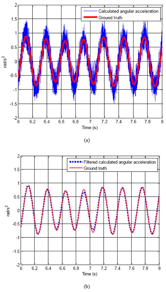
Plots of comparison of ground truth angular acceleration about XB axis and calculated angular acceleration about XB axis using acceleration outputs from accelerometers inside the instrument: (a) without using a band-pass filter, and (b) with the band-pass filter
4. Discussion
In applications such as micromanipulation where centripetal acceleration term is relatively very small, since we can ignore centripetal acceleration term, only a pair of two accelerometers is required for calculation of any of the three angular acceleration components, making placement design simple. The proposed approach separates sensing three DOF angular acceleration into sensing one DOF angular acceleration using a pair with two accelerometers, and sensing two DOF angular acceleration using a pair of three accelerometers. Since the optimal placement of the pair with two accelerometers does not affect the optimal placement of the other three accelerometers, placement design is simple.
Sensing resolution improvement by following the placement propositions has been shown by comparing sensing noise in different placement configurations in a hand-held microsurgical instrument. As shown in Table 2, with the proposed configuration which follows the propositions described, angular acceleration noise is reduced by 72% and 17% comparing to the noise with Micron configuration and Cube configuration, respectively.
In comparison of RMS noise between proposed configuration and Cube configuration in Table 1, proposed configuration provides lesser noise in αx by about six times while providing the same noise level in the other two components αy and αz. This is mainly due to the larger separation distance (d3 in Figure 10) in the proposed configuration. Since Cube configuration requires symmetry placement of accelerometers, it cannot make full use of the space available, and hence causing relatively higher noise in αx due to smaller separation distance.
Apart from the resolution improvement, and the design simplicity, another advantage of the proposed placement is flexibility in placing the accelerometers. As mentioned in section 2.1.1, in sensing rigid-body motion with very small angular velocities such as micromanipulation, accelerometers can be placed anywhere along the line of their sensing axes [28] with negligible errors. Therefore, the placement configurations shown in section 2 are a few of many possible configurations. For example, consider the configuration for six DOF motion sensing as shown in Figure 17. The accelerometers can be placed anywhere along Line ij; where i=1,2, or 3; j=x,y, or z.
Figure 17.
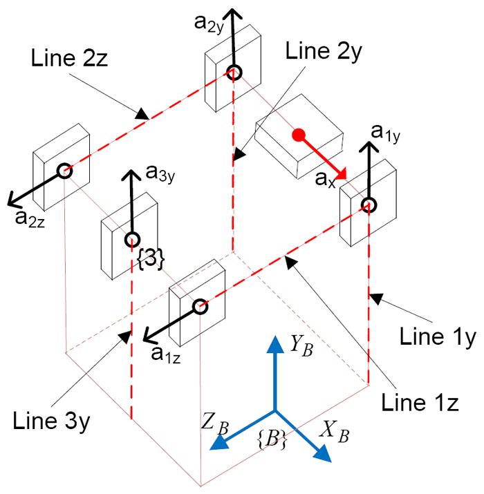
Flexibility of placement of accelerometers
The plots shown in Figure 16 shows that the angular acceleration formulae (49-51) are correct although there are some errors. The errors might have resulted from the combined errors of the inaccurate positioning and orientation of the accelerometers, noises in the accelerometer outputs, accuracy and resolution of the measurement of the ball position by M2S2. The positioning and orientation errors of the accelerometers can be known by using high precision rotation and translation stages and they can be corrected.
The advantage of Cube configuration is its ability to provide accurate angular acceleration when the rigid-body motion involves relatively high angular velocities. Main disadvantage of the cube configuration is that if the total space available is not in cube shape such as a thin slice of space, it cannot be employed. However, the propositions described are so flexible that the configurations can be made suitable for limited available space such as a thin slice of space.
5. Conclusion
Placement (location and orientation) of accelerometers to obtain the least possible angular acceleration noise in micromanipulation tasks have been proposed. The placement configurations of accelerometers should follow the propositions described to obtain the least possible angular acceleration noise. Sensing resolution provided by proposed configuration employed in a hand-held instrument has been proved to be higher than those provided by existing configurations employed in the same-sized instrument. Correctness of the angular acceleration formulae for proposed configuration has been shown by experiment. The placement propositions described would serve as guidelines for placement of accelerometers in future hand-held instruments to be used in micromanipulation tasks. They are valuable to sensing any rigid-body motion having relatively low angular velocities with limited available space to mount accelerometers.
Acknowledgments
Intelligent Handheld Instrument for Microsurgery & Biotech Micromanipulation project is funded by Agency for Science, Technology & Research (A*STAR), the College of Engineering, Nanyang Technological University, and the National Institutes of Health: grant nos. R01 EB000526 and R01 EB007969. The authors thank them for the financial support of this work.
Biographies
Win Tun Latt received the B.E. (Electronics) degree from Yangon Technological University, Myanmar in 2000. He earned the M.Sc. (Biomedical Engineering) degree, and the Ph.D. degree from the Nanyang Technological University (NTU), Singapore, in 2004 and 2010 respectively. He is a recipient of a gold medal in Singapore Robotics Games in 2005. He worked as a member of research staff in NTU from 2005 to 2010. He is currently working as a post-doctoral research associate in the area of biomedical robotics in Imperial College London, UK. His research interests include sensing systems, signal processing, medical robotics, and mechatronics.
U-Xuan Tan received the BEng degree in mechanical and aerospace engineering from the Nanyang TechnologicalUniversity, Singapore, in 2005. He earned the PhD degree from the Nanyang Technological University, Singapore in 2010. He is currently working as a post-doctoral research associate in Maryland University, USA. His research interests include mechatronics, control systems, smart materials, sensing systems, medical robotics, rehabilitative technology, mechanism design, kinematics, and signal processing.
Cameron N. Riviere received the BS degree in aerospace engineering and ocean engineering from the Virginia Polytechnic Institute and State University, Blacksburg, in 1989 and the PhD degree in mechanical engineering from The Johns Hopkins University, Baltimore, MD, in 1995. Since 1995, he has been with the Robotics Institute at Carnegie Mellon University, Pittsburgh, PA, where he is presently an Associate Research Professor and the Director of the Medical Instrumentation Laboratory. He is also an adjunct faculty member of the Department of Rehabilitation Science and Technology at the University of Pittsburgh. His research interests include medical robotics, control systems, signal processing, learning algorithms, and biomedical applications of human-machine interfaces. Dr. Riviere served as one of the guest editors of the Special Issue on Medical Robotics of the journal proceedings of the IEEE in September 2006.
Wei Tech Ang received the BEng and MEng degrees in mechanical and production engineering from the Nanyang Technological University, Singapore, in 1997 and 1999, respectively, and the PhD degree in robotics from Carnegie Mellon University, Pittsburgh, PA, in 2004. He has been an Assistant Professor in the School of Mechanical and Aerospace Engineering, Nanyang Technological University, since 2004. His research interests include sensing and sensor, actuators, medical robotics, rehabilitative and assistive technology, mechanism design, kinematics, signal processing, and learning algorithms.
Footnotes
Publisher's Disclaimer: This is a PDF file of an unedited manuscript that has been accepted for publication. As a service to our customers we are providing this early version of the manuscript. The manuscript will undergo copyediting, typesetting, and review of the resulting proof before it is published in its final citable form. Please note that during the production process errors may be discovered which could affect the content, and all legal disclaimers that apply to the journal pertain.
References
- 1.Das H, Zak H, Johnson J, Crouch J, Frambach D. Evaluation of a telerobotic system to assist surgeons in microsurgery. Computer Aided Surg. 1999;4:15–25. doi: 10.1002/(SICI)1097-0150(1999)4:1<15::AID-IGS2>3.0.CO;2-0. [DOI] [PubMed] [Google Scholar]
- 2.Schurr MO, Buess G, Neisius B, Voges U. Robotics and telemanipulation technologies for endoscopic surgery. A review of the ARTEMIS project. Surgical Endoscopy. 2000 Apr;14:375–81. doi: 10.1007/s004640020067. [DOI] [PubMed] [Google Scholar]
- 3.Marohn CMR, Hanly CEJ. Twenty-first century surgery using twenty-first century technology: surgical robotics. current surgery. 2004 Sep/Oct;61(5) doi: 10.1016/j.cursur.2004.03.009. [DOI] [PubMed] [Google Scholar]
- 4.Taylor R, et al. A steady-hand robotic system for microsurgical augmentation. Int J Robot Res. 1999;18:1201–1210. [Google Scholar]
- 5.Bose B, Kalra AK, Thukral S, Sood A, Guha SK, Anand S. Tremor compensation for robotics assisted microsurgery. Proceedings of the Annual International Conference of the IEEE Engineering in Medicine and Biology Society; Oct 29-Nov 1; 1992. pp. 1067–1068. [Google Scholar]
- 6.Ang WT, Khosla PK, Riviere CN. An intelligent hand-held microsurgical instrument for improved accuracy. Proceedings of the 23rd Annual EMBS Intl Conf; Oct 25-28; Istanbul, Turkey. [Google Scholar]
- 7.Ang WT, Riviere CN, Khosla PK. Design and implementation of active error canceling in a hand-held microsurgical instrument. Proc IEEE/RSJ Intl Conf Intell Robots and Systems; Hawaii. 2001. pp. 1106–1111. [Google Scholar]
- 8.Riviere CN, Ang WT, Khosla PK. Toward active tremor canceling in handheld microsurgical instruments. IEEE Trans on robotics and automation. 2003 Oct;19(5) [Google Scholar]
- 9.Elble RJ, Koller WC. Tremor. Baltimore: Johns Hopkins; 1990. [Google Scholar]
- 10.Singh SPN, Riviere CN. Physiological Tremor Amplitude during Retinal Microsurgery. Proc 28th Annu International Conference of the IEEE Northeast Bioengineering Conference. 2002 Apr;:171–172. [Google Scholar]
- 11.Ang WT. doctoral thesis. the Robotics Institute, CMU; Pittsburgh, Pennsylvania: May, 2004. Active tremor compensation in handheld instrument for microsurgery; p. 15213. [Google Scholar]
- 12.Ang WT, Khosla PK, Rivere CN. Design of All-Accelerometer Inertial Measurement Unit for Tremor Sensing in Hand-held Microsurgical Instrument. Proc IEEE international Conference on Robotics and Automations; Taipei, Taiwan. September 14-19; 2003. pp. 1781–1786. [Google Scholar]
- 13.DiNapoli LD. The measurement of angular velocities without the use of gyros. Philadelphia: The Moore School of Electrical Engineering, University of Pennsylvania; 1965. pp. 34–41. [Google Scholar]
- 14.Schuler AR. Measuring rotational motion with linear accelerometers. IEEE Transactions on AES. 1967;3:465–472. [Google Scholar]
- 15.Mital NK, King AI. Computation of rigid-body rotation in three-dimensional space from body-fixed linear acceleration measurements. Journal of Applied mechanics Trans ASME. 1979;46:925–930. [Google Scholar]
- 16.Padgaonkar AJ, Krieger KW, King AI. Measurement of angular acceleration of a rigid body using linear accelerometers. Journal of Applied Mechanics, Transactions ASME. 42(Ser E (3)):552–556. [Google Scholar]
- 17.Chen IH, Lee SC, DeBra DB. Gyroscope Free Strapdown Inertial Measurement Unit by Six Linear Accelerometers. Journal of Guidance, Control, and Dynamics. 1994 March-April;17(2):286–290. [Google Scholar]
- 18.Zappa B, Legnani G, Bogert AJ, Adamini R. On the number and placement of accelerometers for angular velocity and acceleration determination. Journal of Dynamic Systems, Measurement, and Control. 2001 Sep;123:552–553. [Google Scholar]
- 19.Wang Q, Ding M, Zhao P. A New Scheme of Non-gyro Inertial Measurement Unit for Estimating Angular Velocity. the 29th Annual Conference of the IEEE Industrial Electronics Society; 2-6 Nov; 2003. pp. 1564–1567. [Google Scholar]
- 20.Tan CW, Park S. Design of Accelerometer-Based Inertial Navigation Systems. IEEE Transactions on Instrumentation and Measurement. 2005 December;54(6) [Google Scholar]
- 21.Akeila E, Salcic Z, Swain A. Implementation, calibration and testing of GFINS models based on six-accelerometer cube. TENCON IEEE Region 10 Conference; 19-21 Nov; 2008. pp. 1–6. [Google Scholar]
- 22.Kao CF, Chen TL. Design and analysis of an orientation estimation system using coplanar gyro-free inertial measurement unit and magnetic sensors. Sensors and Actuators A: Physical. 2008;144(2):251–262. [Google Scholar]
- 23.Onodera R, Mimura N. Stability and error analysis of a new 6 dof motion sensor using multiple accelerometers. IEEE Sensors conference. 2008:752–755. [Google Scholar]
- 24.Latt WT, Tan U-X, Widjaja F, Shee CY, Ang WT. A Study of a Hand-held Instrument’s Angular Motion due to Physiological Tremor in Micromanipulation Tasks. 30 th Annual International Conference of the IEEE Engineering in Medicine and Biology Society; Vancouver, British Columbia, Canada. Aug 20-24, 2008; pp. 1952–1955. [DOI] [PubMed] [Google Scholar]
- 25.Win TL, Tan UX, Shee CY, Ang WT. Design and calibration of an optical micro motion sensing system for micromanipulation tasks. Proc IEEE International Conference on Robotics and Automation; Roma, Italy. Apr. 2007; pp. 3383–3388. [Google Scholar]
- 26.Latt WT, Tan UX, Widjaja F, Shee CY, Ang WT. Handling Light Disturbances in a Micro Motion Sensing System and Investigation of the System Performance. IEEE International Conference on Biomedical Robotics and Biomechatronics; Scottsdale, Arizona, USA. Oct 2008. [Google Scholar]
- 27.Latt WT, Tan UX, Ananda ES, Shee CY, Ang WT. Design, implementation, and calibration of an optical micro motion sensing system for micromanipulation tasks. IEEE sensors journal. Under Review. [Google Scholar]
- 28.Latt WT, Tan U-X, Shee CY, Riviere CN, Ang WT. Compact Sensing Design of a Hand-held Active Tremor Compensation Instrument. IEEE sensors journal. 2009 December 1;9(12):1864–1871. doi: 10.1109/JSEN.2009.2030980. [DOI] [PMC free article] [PubMed] [Google Scholar]


