Abstract
Plasmonic-based electrochemical impedance spectroscopy (P-EIS) is developed to investigate molecular binding on surfaces. Its basic principle relies on the sensitive dependence of surface plasmon resonance (SPR) signal on surface charge density, which is modulated by applying an AC potential to a SPR chip surface. The AC component of the SPR response gives the electrochemical impedance, and the DC component provides the conventional SPR detection. The plasmonic-based impedance measured over a range of frequency is in quantitative agreement with the conventional electrochemical impedance. Compared to the conventional SPR detection, P-EIS is sensitive to molecular binding taking place on the chip surface, and less sensitive to bulk refractive index changes or non-specific binding. Moreover, this new approach allows for simultaneous SPR and surface impedance analysis of molecular binding processes.
Keywords: SPR, Surface Plasmon Resonance, Electrochemical Impedance Spectroscopy, Plasmonic-based impedance spectroscopy, P-EIS
Introduction
Electrochemical impedance spectroscopy (EIS) is a powerful electrochemical technique for studying various surface processes and properties.1, 2 It measures electrical current response to a potential applied to an electrode, which is extremely sensitive to molecular adsorption taking place on the electrode surface. EIS has also been widely used as a label-free detection method to study various molecular binding processes, such as antigen-antibody3-7, protein-DNA interaction8-11, and DNA hybridization12-16, and to monitor various cellular processes. Surface plasmon resonance (SPR) is another label-free detection technique for real-time study of molecular interactions.17-25 Unlike EIS, SPR is an optical method that detects and images changes in refractive index near a metal surface (sensor chip).26-29 However, SPR signal is prone to interference due to changes in bulk refractive index, and SPR signal decreases with the mass of molecules, making small molecule detection challenging. Besides electrochemical and optical based techniques, piezoelectric sensor (e.g. Quartz Crystal Microbalance)30-32 is another main category of label free method for molecular binding detection. Immunoassay is based on the highly specific molecular recognition between antigen and antibody.33,34 Immunoglobulin G (IgG) antibody is one of the most common and important proteins in the immune system and clinical application, which is also widely used in the immunoassay. One IgG molecule with a molecular weight of ~150 kDa has two identical antigen binding sites, to form antigen/antibody complexes. 35
Recently we have shown that it is possible to perform electrochemical measurements, such as cyclic voltammetry, based on a plasmonic detection. In other words, an electrochemical current can be determined and imaged optically, which is in contrast to the conventional electrochemistry that relies on electrical measurement.36-40 We have also shown that electrochemical impedance can be obtained based on the plasmonic detection.36 Here we show that it is possible to obtain impedance spectrum by measuring impedance vs. frequency over a wide frequency range (from to 0.01 Hz to 10 kHz) with the plasmonic-based electrochemical impedance spectroscopy (P-EIS). We validate P-EIS by comparing it with the simultaneously recorded electrically measured EIS, and with theoretical modeling.
Furthermore, as the new technique combined the features of both SPR and EIM, P-EIS has more potential in the area of molecular binding studies, which is demonstrated by studying human IgG and anti-human IgG interaction as a model system. The kinetics and affinity results from P-EIS are compared with the simultaneously recorded SPR.
Experimental Section
Materials
6-mercaptohexanoic acid, 3-mercapto-1-propanol, NaCl, KCl, Na2HPO4, KH2PO4, NaF, sodium acetate, glucose, N-hydroxysuccinimide (NHS), N-(3-Dimethylaminopropyl)-N’-ethylcarbodiimide hydrochloride (EDC), ethanolamine, IgG from human serum (IgG), anti-human IgG (Fab specific) antibody (anti-IgG), albumin from bovine serum (BSA) were purchased from Sigma-Aldrich (St. Louis, MO). 1x phosphate buffered saline (1x PBS, 10 mM Na2HPO4-KH2PO4, 137 mM NaCl, 2.7 mM KCl, pH 7.4), 10 mM sodium acetate (pH 5.0) were prepared as stock solution.
Plasmonic-based Impedance Measurements
BI-2000 SPR instrument with an EC-dual-flow analysis module (Biosensing Instrument Inc.) was used in the experiments. The SPR sensor chip was a BK7 glass cover slide coated with 2 nm chromium followed by 47 nm gold by thermal evaporator at high vacuum (3 × 10⁻⁶ Torr). The Au sensor chip was used as working electrode (WE) and a glassy carbon electrode or Pt wire served as counter electrode (CE). Its potential was controlled with respect to Ag/AgCl reference electrode (RE) by a potentiostat (EG&G Model 283 Potentiostat/Galvanostat, Princeton Applied Research). Potential modulations with different frequencies and amplitudes were applied to the chip using an external function generator (Model DS345, Stanford Research Systems). The SPR responses to the modulations were measured by a lock-in amplifier (Model SR830 DSP, Stanford Research Systems). The amplitude and phase outputs from the lock-in amplifier, as well as the corresponding potential, current, SPR signals were collected with the sampling rate of 10,000 points per second by Data Acquisition (NI USB-6251, National Instruments) using a program written in MATLAB.
Chip preparation
The Au sensor chip was rinsed with water and ethanol, and then annealed with hydrogen flame to further clean the surface before each SPR and plasmonic-based impedance measurement. The chip was modified by immersing it in 1 mM 1:1 6-mercaptohexanoic acid and 3-mercapto-1-propanol mixture solution in ethanol for 24 h. IgG was subsequently immobilized on the sensor chip using the standard amine-coupling chemistry using the flow-through system of BI-2000 instrument with 1x PBS as running buffer at a flow rate of 10 μL/min. The chip surface was first activated with a mixture of 0.4 M EDC and 0.1 M NHS for 8 min, and then exposed to 0.1 mg/mL IgG (in 10 mM sodium acetate buffer, pH 5.0) for 8 min. Finally, the residual activated groups on the chip surface were blocked with 1 M ethanolamine (pH 8.5) for 8 min. The surface modification processes were monitored and characterized by SPR in real time. After IgG immobilization, 1x PBS running buffer continued to flow over the surface at a flow rate of 60 μL/min to stabilize the system. For each sample injection cycle, the surface was exposed to the sample for 75 s, then to the running buffer for 400 s.
Results and discussion
Basic principle and setup
In a conventional EIS measurement, a potential modulation (amplitude ΔV and frequency ω) is applied to an electrode surface, and the current response (ΔI) is detected electrically, from which surface impedance, Z, at frequency ω is determined by Z(ω)=ΔV/ΔI. In contrast, P-EIS is based on the sensitive dependence of SPR on surface charge density, which does not require electrical current measurement.36,39 Responding to the potential modulation (ΔV), the surface charge density (Δσ) oscillates, which induces a modulation in the SPR angle, Δθ, that is detected optically. We have shown that Δθ is proportional to Δσ given by Δσ = αΔθ, where α is a coefficient that can be calibrated experimentally or calculated theoretically.36 Since current density (ΔJ) is related to charge density by ΔJ=jωΔσ, we have A(ω)=jωαΔθ/ΔV, where A is admittance per unit area, or admittance density, and j=√(−1). Note that admittance is the inverse of impedance. This relation allows us to determine local impedance based on the AC component of the SPR angle (Δθ). We note that the DC component of the SPR angle can be determined simultaneously, which provides conventional SPR detection.
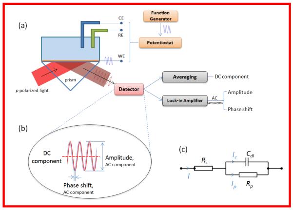
The basic principle summarized above can be realized with different experimental setups. The present work uses the setup illustrated in Fig. 1(a). It is based on the widely used Krectchmann configuration, in which a light beam of wavelength 635 nm is directed onto the SPR chip surface through a prism, and the SPR angle is measured from the reflected beam. To obtain electrical impedance, a sinusoidal potential from a function generator is applied via the potentiostat to the Au sensor chip (WE), the AC components of the SPR response is detected with lock-in technique and the DC component is obtained by directly averaging the SPR signal (Fig. 1(b)).
Figure 1.
(a) Schematic illustration of the setup. AC modulation from a function generator was applied to the Au sensor chip (WE) via a potentiostat. The DC component of the SPR response was obtained by directly averaging the SPR signal, and the AC component was converted to amplitude signal and phase shift signal by lock-in amplifier. (b) Illustration of DC component of SPR (averaged SPR signal), amplitude (peak-to-peak amplitude) and phase shift (relative to the applied potential) of AC component. (c) Randles equivalent circuit used to model both the conventional and plasmonic-based impedance spectra.
Comparison of P-EIS with conventional EIS and impedance model
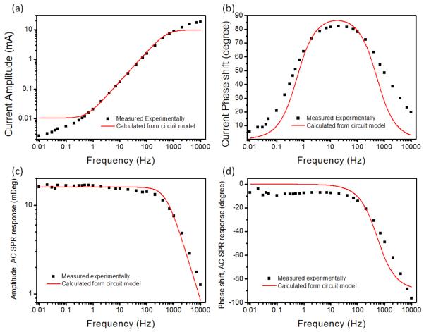
P-EIS works in imaging mode, providing local information with high spatial resolution. However, in the present work, we operated P-EIS in non-imaging mode in order to compare P-EIS data with electrically measured EIS. We recorded the current response to a potential modulation applied to the sensor surface electrically, and the corresponding SPR response of the same surface optically. The amplitudes and phases of the AC components of the current and SPR response were determined by either fast Fourier transform (FFT) or lock-in amplifier at different frequencies, ranging from to 0.01 Hz to 10 kHz, and the results are shown in Fig. 2. From the measured amplitudes and phases, we can obtain the conventional EIS and P-EIS. However, we first analyze the amplitudes and phases because they are directly measured quantities and can be easily converted into impedance or admittance.
Figure 2.
Amplitudes and phase shifts of electrical current (a and b) and AC response of SPR signal (c and d) at different frequencies in 0.5 M NaF. The red lines are fitting curves based on the Randles equivalent circuit model to the experimental data (black square), showing that the simple model explains well both the electrical and plasmonic-based impedance spectra.
As shown in Figs. 2(a) and 2(b) (filled squares), the amplitude of current increases with frequency monotonically, while the phase of the current increases from nearly zero at low frequencies to a maximum of 90 degrees around 2 kHz before dropping to nearly zero again at higher frequencies. These results can be explained in terms of the widely used Randles equivalent circuit model shown in Fig.1(c)). According to the model, the current amplitude is given by
| (1) |
where Rs represents the solution resistance, and Rp and Cdl are the double layer resistance and capacitance, respectively. Eq. 1 predicts that the amplitude increases with frequency. The same model predicts that the phase given by
| (2) |
increases with frequency from zero to 90 degrees and then drops to zero at high frequencies. Quantitative fittings of the current amplitude and phase shift are red solid lines shown in Figs. 2(a) and 2(b) with Rs, Cdl and Rp as fitting parameters shown in Table 1.
Table 1.
Fitting parameters to the Randles equivalent circuit model (Cdl is interfacial capacitance, Rp is interfacial resistance, and Rs is solution phase resistance).
| Plasmonic-based Impedance | Conventional Impedance |
|
|---|---|---|
| Cdl / μF | 9.68 ± 0.10 | 9.56 ± 0.13 |
| Rp / kΩ | 49.6 ± 5.6 | 29.0 ± 1.5 |
| Rs / Ω | 32.8 ± 39.9 | 31.1 ± 48.1 |
The amplitude and phase of the AC SPR response are shown in Figs. 2(c) and 2(d), respectively. Although they are related to the amplitude and phase measured electrically, the following consideration must be taken into account when comparing the quantities measured optically and electrically. The SPR angle response is related to surface charge, which is the charge stored in the capacitor in the Randles model. Consequently, the relation ΔJ=jωΔσ shown earlier represents AC current through the capacitor (Ic in Fig. 1(c)), which is the polarization or double layer charging current. The current through the resistor, Rp, corresponding to faradic current, is not directly included in the above relation. This important point is further confirmed in Fig. S3 (supporting information), which shows current and AC SPR amplitude in 0.5 M NaF solution saturated with O2 and saturated N2, respectively. Due to the reduction of dissolved O2, the direct electrical current at lower frequencies is substantially higher in the presence of saturated O2 than that in N2. In contrast, the amplitudes of AC SPR component with and without O2 are similar, indicating that the AC response of the SPR signal is insensitive to O2 reduction current (faradic current). Based on this consideration, one may conclude that the SPR impedance probes only the capacitive component of the total interfacial impedance.
However, the above conclusion applies only to cases where the following two conditions are met: solution resistance is small, and the refractive indices of oxidized and reduced species associated with faradic current are the same. If the solution resistance is not negligible, then Rs in the Randles model will affect potential drop across the capacitor, and thus affecting the AC SPR response. Since the potential drop is determined not only by the capacitor, Cdl, but also by Rp, the SPR impedance contains both interfacial capacitive and resistive components in general36. If the oxidized and reduced species have different refractive indices (the usual case), then the SPR response contains also the faradic component associated with the refractive index change. In the cases of O2 reduction studied in the present paper, both the solution resistance and the influence of refractive index difference between the oxidized and reduced species are small, such that the AC response of the SPR signal mainly reflects the capacitive component of the impedance.
If we assume that the solution resistance and the faradic current dominated by the dissolved O2 are both small, then the AC response of the SPR signal is given by Δθ = ΔJc/(jωα), where Jc is the capacitive (double layer charging) current. Jc can be calculated from the Randles model using the Rs, Cdl and Rp obtained by fitting the current amplitude and phase data with the Randles model. Figs. 2(c) and (d) show the measured (black square) and calculated (red solid line) amplitude and phase of the AC SPR response with frequency varying from 0.01 Hz to 10 kHz. It is clear that the calculated results are in good agreement with the experimental data, which validates the relationship between the SPR and current responses to the potential modulation.
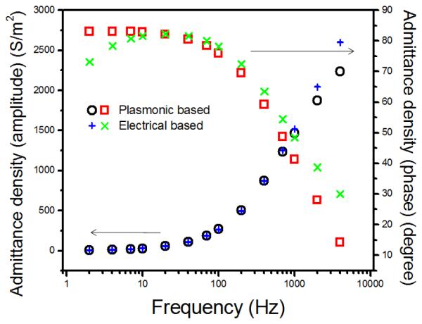
We has discussed earlier that interfacial admittance density can be determined from the AC response of the SPR signal by Ap(ω)=jωαΔθ/ΔV, which can be compared with the admittance density directly obtained from the electrical current based on Ae(ω) = ΔJ/ΔV, where the current density, ΔJ, is determined from the total measured current divided by the electrode area. Fig. 3 shows the Bode plots of plasmonic-based admittance density (Ap) and electrical-based admittance density (Ae). Both the amplitudes and phase shifts of the admittance density measured by the present method and the conventional approach are in good agreement. The Bode plots can be fit with the Randles equivalent circuit model, and the fitting parameters are shown in Table 1. The fitting parameters, Cdl and Rs, of the plasmonic and electrical measurements are in excellent agreement. However, Rp values from the two methods show substantial difference, which is due to the faradic contribution that is not taken into account in the plasmonic-based impedance.
Figure 3.
Bode plot of plasmonic-based admittance density (Ap, amplitude (black circle), phase (red square)) and electrical-based admittance density (Ae, amplitude (blue +), phase (green x)) from 4 kHz to 2 Hz in 0.5 M NaF.
Simultaneous P-EIS and SPR detections of molecular binding processes
After elucidating the mechanism of the P-EIS, we now turn to the application of P-EIS to study molecular binding processes. As shown previously, it is the admittance density, rather than impedance, that is directly related to the experimentally measurable quantity, Δθ/ΔV. For this reason, we express results below in terms of admittance density, instead of impedance. We note also that both P-EIS and SPR can be recorded simultaneously from the AC and DC components of the SPR response, respectively, with our setup. This capability allows us to compare the two sensing principles, impedance and SPR, in the same platform, and to benefit from the advantages of both techniques.
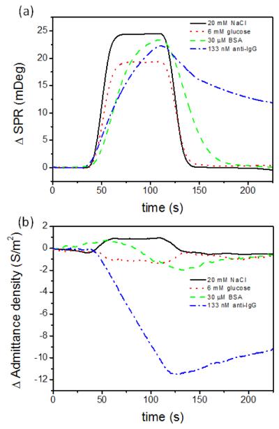
SPR is sensitive to surface binding but also to changes in the bulk index refraction of solution, which must be carefully corrected when analyzing SPR data. In contrast, impedance detection is sensitive to surface binding but not to changes in the bulk refractive index. To demonstrate this point, four different solutions (NaCl, glucose, BSA and anti-IgG) were injected and flow over an IgG modified Au sensor chip, during which both the SPR response (DC SPR component) and admittance density response (AC SPR component) were recorded simultaneously. All the chemicals were dissolved in 1xPBS to avoid any matrix mismatch. Among them, only anti-IgG was supposed to show specific interaction with the IgG on the sensor surface, while NaCl and glucose would contribute to the SPR signal due to the refractive index change in the bulk solution, and BSA could have additional non-specific binding41-43. As shown in Fig. 4(a), the SPR responses to the injections of NaCl and glucose into the solution cell increase rapidly, and then reach steady levels, followed by rapid decreases back to the original levels as NaCl and glucose are replaced with the running buffer. In the case of BSA, the SPR signal also increases and then returns to the level before the sample injection, but the increase and decrease occur at much slower rates than the cases of NaCl and glucose. We attribute the SPR response to BSA to non-specific and reversible adsorption. Finally, the injection of anti-IgG results in a relative slow increase in the SPR response and then followed by an even slower decrease after switching anti-IgG containing solution to the PBS running buffer. This SPR response follows the expected association and dissociation kinetics, and we will return to this later.
Figure 4.
SPR (a) admittance density responses (b) to the injections of 20 mM NaCl (black solid line), 6 mM glucose (red dot line), 30 μM BSA (green dash line) and 133 nM anti-IgG (blue dash dot line) on IgG surface with the flow rate of 60 μL/min. All of sample molecules were dissolved in 1x PBS (same as the running buffer). 100 Hz, 200 mVpp potential modulation with 120 mV bias was applied.
Fig. 4(b) shows the corresponding admittance density responses. Unlike SPR, the injection of NaCl and glucose caused relatively small changes in the measured admittance, which confirms that admittance is not sensitive to changes in the bulk refractive index. Carefully examining the admittance responses to NaCl and glucose revealed that former resulted in a small increase while the latter resulted in a small decrease in admittance. The small changes in the admittance upon injection of NaCl and glucose may be attributed to changes in the solution conductivity. For BSA, the admittance exhibits also a small response due to the non-specific binding of BSA on IgG surface, but the response is much smaller than that in the corresponding SPR response. The above results indicate that P-EIS is less prone to interferences due to bulk refractive index and non-specific binding taking place on the sensor surface than SPR.
The injection of anti-IgG led to a large admittance response corresponding to the association of anti-IgG with IgG, followed by a slower dissociation process. The decrease in the admittance is expected because the binding of anti-IgG to IgG on the sensor surface lowers the interfacial capacitance. Note that A ~ jωCdl for a double layer dominated interface. Admittance density vs. frequency scan was measured before and after anti-IgG binding (Fig. S4, supporting information). Fitting the admittance density spectra with the Randles model with fitting parameters shown in Table S1 (supporting information) further confirms that specific binding of anti-IgG to IgG results in a decrease in the interfacial capacitance.
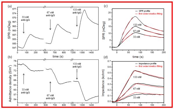
We have studied anti-IgG/IgG interactions by injections of different concentrations of anti-IgG successively into the SPR flow cell, and recorded both the SPR response (DC component) and admittance density (AC component) simultaneously. Fig. 5(a) is the SPR sensorgrams showing the characteristic association and dissociation kinetics, while Fig. 5(b) is the admittance density recorded simultaneously showing the responses associated with the same processes (Fig. 5(b)). We found that fitting the entire DC SPR profiles at various concentrations with the simple first order kinetics globally was difficult (Fig. 5(c)). This is because that the DC SPR contains the contributions from bulk refractive index changes and nonspecific binding, which must be minimized and corrected via proper reference subtraction to achieve meaningful fitting.44 In contrast, the impedance, the inverse of admittance density shown in Fig. 5(d), is less sensitive to bulk refractive index and nonspecific binding effects, and global fitting of the impedance profiles at different concentrations produce much more satisfactory results. For comparison and self-consistency check, we also fit portions of the SPR profiles with kinetic constants and binding affinity listed in Table 2. The kinetic study further illustrates the unique strengths of the impedance approach.
Figure 5.
SPR (a) and admittance density (b) responses to successive injections of anti-IgG from lower to higher concentration on IgG surface. Arrows indicate injections of anti-IgG with different concentrations. The running buffer is 1x PBS with a flow rate of 60 μL/min. 100 Hz, 200 mVpp potential modulation with 120 mV bias was applied. (c) overlays the SPR binding profiles at different concentrations, and (d) is the corresponding plasmonic-based impedance (inverse of admittance density) profiles. The red lines are first order kinetics fitting curves.
Table 2.
Association rate constant (ka), dissociation rate constant (kd) and binding affinity (KD = kd/ka) for SPR (DC component) and impedance (AC component) for IgG-anti-IgG binding.
| ka (M−1s−1) | kd (s−1) | KD (nM) | |
|---|---|---|---|
| SPR | 4.68 × 10⁴ | 3.90 × 10⁻³ | 83.3 |
| P-EIS | 3.69 × 10⁴ | 2.28 × 10⁻³ | 61.8 |
Conclusion
We have demonstrated that electrochemical impedance spectroscopy can be performed based on plasmonic detection over a wide frequency range. To validate the technique, we have compared the plasmonic-based impedance spectroscopy with the simultaneously measured conventional electrochemical impedance spectroscopy and surface plasmon resonance (SPR) detection. The comparison shows that the plasmonic and electrical measurements of impedance are equivalent when double layer charging dominates the impedance, but require additional considerations if there are substantial faradic current and solution resistance. The impedance results measured by both plasmonic and electrical approaches are well explained in term of Randles’ circuit model, with fitting parameters consistent with each other, which further validates the new plasmonic impedance measurement. As an example to demonstrate applications of the plasmonic-based impedance spectroscopy, molecular binding processes have been studied by simultaneously recording the plasmonic-based impedance and conventional SPR responses. Both impedance and SPR can detect and follow the kinetics of protein association and dissociation processes, but the plasmonic-impedance response is less sensitive to changes in bulk refractive index and non-specific adsorption, thus providing a complementary label-free detection technology to the conventional SPR detection.
Supplementary Material
Acknowledgement
We thank NIH (R21RR026235), National Natural Science Foundation of China (No. 20975060), National Basic Research Program of China (No. 2007CB310501, No. 2011CB935704) for support.
Footnotes
Supporting Information Available.
Additional information as noted in text. This material is available free of charge via the Internet at http://pubs.acs.org.
REFERENCES
- (1).Daniels JS, Pourmand N. Electroanal. 2007;19:1239–1257. doi: 10.1002/elan.200603855. [DOI] [PMC free article] [PubMed] [Google Scholar]
- (2).Katz E, Willner I. Electroanal. 2003;15:913–947. [Google Scholar]
- (3).Balkenhohl T, Lisdat F. Anal. Chim. Acta. 2007;597:50–57. doi: 10.1016/j.aca.2007.06.041. [DOI] [PubMed] [Google Scholar]
- (4).Diniz FB, Ueta RR, Pedrosa AMD, Areias MD, Pereira VRA, Silva ED, da Silva JG, Ferreira AGP, Gomes YM. Biosens. Bioelectron. 2003;19:79–84. doi: 10.1016/s0956-5663(03)00213-6. [DOI] [PubMed] [Google Scholar]
- (5).Patolsky F, Filanovsky B, Katz E, Willner I. J. Phys. Chem. B. 1998;102:10359–10367. [Google Scholar]
- (6).Pei RJ, Cheng ZL, Wang EK, Yang XR. Biosens. Bioelectron. 2001;16:355–361. doi: 10.1016/s0956-5663(01)00150-6. [DOI] [PubMed] [Google Scholar]
- (7).Wu CC, Lin CH, Wang WS. Talanta. 2009;79:62–67. doi: 10.1016/j.talanta.2009.03.006. [DOI] [PubMed] [Google Scholar]
- (8).Bogomolova A, Komarova E, Reber K, Gerasimov T, Yavuz O, Bhatt S, Aldissi M. Anal. Chem. 2009;81:3944–3949. doi: 10.1021/ac9002358. [DOI] [PubMed] [Google Scholar]
- (9).Cai H, Lee TMH, Hsing IM. Sensor. Actuat. B-Chem. 2006;114:433–437. [Google Scholar]
- (10).Chang HX, Li JH. Electrochem. Commun. 2009;11:2101–2104. [Google Scholar]
- (11).Li CZ, Long YT, Lee JS, Kraatz HB. Chem. Commun. 2004:574–575. doi: 10.1039/b314642a. [DOI] [PubMed] [Google Scholar]
- (12).Baur J, Gondran C, Holzinger M, Defrancq E, Perrot H, Cosnier S. Anal. Chem. 2010;82:1066–1072. doi: 10.1021/ac9024329. [DOI] [PubMed] [Google Scholar]
- (13).Cai W, Peck JR, van der Weide DW, Hamers RJ. Biosens. Bioelectron. 2004;19:1013–1019. doi: 10.1016/j.bios.2003.09.009. [DOI] [PubMed] [Google Scholar]
- (14).Gooding JJ. Electroanal. 2002;14:1149–1156. [Google Scholar]
- (15).Wang Y, Li CJ, Li XH, Li YF, Kraatz HB. Anal. Chem. 2008;80:2255–2260. doi: 10.1021/ac7024688. [DOI] [PubMed] [Google Scholar]
- (16).Xu DK, Xu DW, Yu XB, Liu ZH, He W, Ma ZQ. Anal. Chem. 2005;77:5107–5113. doi: 10.1021/ac050192m. [DOI] [PubMed] [Google Scholar]
- (17).Mrksich M, Grunwell JR, Whitesides GM. J. Am. Chem. Soc. 1995;117:12009–12010. [Google Scholar]
- (18).Peterlinz KA, Georgiadis RM, Herne TM, Tarlov MJ. J. Am. Chem. Soc. 1997;119:3401–3402. [Google Scholar]
- (19).Green RJ, Frazier RA, Shakesheff KM, Davies MC, Roberts CJ, Tendler SJB. Biomaterials. 2000;21:1823–1835. doi: 10.1016/s0142-9612(00)00077-6. [DOI] [PubMed] [Google Scholar]
- (20).Guedon P, Livache T, Martin F, Lesbre F, Roget A, Bidan G, Levy Y. Anal. Chem. 2000;72:6003–6009. doi: 10.1021/ac000122+. [DOI] [PubMed] [Google Scholar]
- (21).Peterson AW, Heaton RJ, Georgiadis RM. Nucleic Acids Res. 2001;29:5163–5168. doi: 10.1093/nar/29.24.5163. [DOI] [PMC free article] [PubMed] [Google Scholar]
- (22).Karlsson R. J. Mol. Recognit. 2004;17:151–161. doi: 10.1002/jmr.660. [DOI] [PubMed] [Google Scholar]
- (23).Myszka DG. Anal. Biochem. 2004;329:316–323. doi: 10.1016/j.ab.2004.03.028. [DOI] [PubMed] [Google Scholar]
- (24).Hoa XD, Kirk AG, Tabrizian M. Biosens. Bioelectron. 2007;23:151–160. doi: 10.1016/j.bios.2007.07.001. [DOI] [PubMed] [Google Scholar]
- (25).Homola J. Chem. Rev. 2008;108:462–493. doi: 10.1021/cr068107d. [DOI] [PubMed] [Google Scholar]
- (26).Campbell CT, Kim G. Biomaterials. 2007;28:2380–2392. doi: 10.1016/j.biomaterials.2007.01.047. [DOI] [PubMed] [Google Scholar]
- (27).Nelson BP, Grimsrud TE, Liles MR, Goodman RM, Corn RM. Anal. Chem. 2001;73:1–7. doi: 10.1021/ac0010431. [DOI] [PubMed] [Google Scholar]
- (28).Wang SP, Shan XN, Patel U, Huang XP, Lu J, Li JH, Tao NJ. P. Natl. Acad. Sci. USA. 2010;107:16028–16032. doi: 10.1073/pnas.1005264107. [DOI] [PMC free article] [PubMed] [Google Scholar]
- (29).Yao JM, Stewart ME, Maria J, Lee TW, Gray SK, Rogers JA, Nuzzo RG. Angew. Chem. Int. Edit. 2008;47:5013–5017. doi: 10.1002/anie.200800501. [DOI] [PubMed] [Google Scholar]
- (30).Cooper MA, Singleton VT. J. Mol. Recognit. 2007;20:154–184. doi: 10.1002/jmr.826. [DOI] [PubMed] [Google Scholar]
- (31).Liu Y, Yu X, Zhao R, Shangguan DH, Bo Z, Liu G. Biosens. Bioelectron. 2003;19:9–19. doi: 10.1016/s0956-5663(03)00127-1. [DOI] [PubMed] [Google Scholar]
- (32).Marx KA. Biomacromolecules. 2003;4:1099–1120. doi: 10.1021/bm020116i. [DOI] [PubMed] [Google Scholar]
- (33).Delehanty JB, Ligler FS. Anal. Chem. 2002;74:5681–5687. doi: 10.1021/ac025631l. [DOI] [PubMed] [Google Scholar]
- (34).Luppa PB, Sokoll LJ, Chan DW. Clin. Chim. Acta. 2001;314:1–26. doi: 10.1016/s0009-8981(01)00629-5. [DOI] [PubMed] [Google Scholar]
- (35).Silverton EW, Navia MA, Davies DR. P. Natl. Acad. Sci. USA. 1977;74:5140–5144. doi: 10.1073/pnas.74.11.5140. [DOI] [PMC free article] [PubMed] [Google Scholar]
- (36).Foley KJ, Shan X, Tao NJ. Anal. Chem. 2008;80:5146–5151. doi: 10.1021/ac800361p. [DOI] [PubMed] [Google Scholar]
- (37).Shan XN, Patel U, Wang SP, Iglesias R, Tao NJ. Science. 2010;327:1363–1366. doi: 10.1126/science.1186476. [DOI] [PubMed] [Google Scholar]
- (38).Wang SP, Huang XP, Shan XN, Foley KJ, Tao NJ. Anal. Chem. 2010;82:935–941. doi: 10.1021/ac902178f. [DOI] [PubMed] [Google Scholar]
- (39).Wang W, Foley K, Shan X, Wang SP, Eaton S, Nagaraj VJ, Wiktor P, Patel U, Tao NJ. Nature Chem. 2011;3:249–255. doi: 10.1038/nchem.961. [DOI] [PMC free article] [PubMed] [Google Scholar]
- (40).Shan X, Wang S, Wang W, Tao N. Anal. Chem. 2011;83:7394–7399. doi: 10.1021/ac201392r. [DOI] [PMC free article] [PubMed] [Google Scholar]
- (41).Ahluwalia A, Giusto G, DeRossi D. Mat. Sci. Eng. C-Biomim. 1995;3:267–271. [Google Scholar]
- (42).Tijssen P. Practice and Theory of Enzyme Immunoassays, Laboratory Techniques in Biochemistry and Molecular Biology. Elsevier; Amsterdam: 1985. [Google Scholar]
- (43).Silin VV, Weetall H, Vanderah DJ. J. Colloid Interf. Sci. 1997;185:94–103. doi: 10.1006/jcis.1996.4586. [DOI] [PubMed] [Google Scholar]
- (44).Myszka DG. J. Mol. Recognit. 1999;12:279–284. doi: 10.1002/(SICI)1099-1352(199909/10)12:5<279::AID-JMR473>3.0.CO;2-3. [DOI] [PubMed] [Google Scholar]
Associated Data
This section collects any data citations, data availability statements, or supplementary materials included in this article.


