Abstract
There are several artifacts unique to PET/CT imaging, with CT-based attenuation correction (AC) artifacts being among the most commonly reported. AC artifacts from calcified lymph nodes represent clinically significant and easily misinterpreted PET/CT artifacts that have received little attention in the literature. In this case series, we report three cases of calcified lymph nodes causing an AC artifact and one case of a highly calcified lymph node without an AC artifact. All three cases of calcified lymph nodes causing an AC artifact would have resulted in a change in patient staging, and likely management, if the nodes had been misinterpreted as malignant nodes. In PET/CT imaging, this artifact needs to be considered as a potential cause of apparent FDG activity when calcified lymph nodes are present on the CT portion of a PET/CT study in order to avoid misinterpretation and potential patient mismanagement.
Keywords: FDG PET, PET/CT, Artifacts, Attenuation correction
INTRODUCTION
Several artifacts have been described in the literature unique to PET/CT that are not present using dedicated PET scanners. Most of these artifacts are generated by CT-based AC protocols utilized by PET/CT scanners. One of the advantages of using PET/CT is that the AC is easily performed using the CT portion of the exam, obviating the need to perform a separate transmission scan, as is necessary on dedicated PET systems. There are several AC methods for PET and PET/CT scanners; however only with PET/CT utilizing certain AC algorithms will these AC artifacts be generated on the AC PET images. When using CT-based AC, the measured CT Hounsfield units (HU), related to the linear attenuation seen by the x-ray beam, must be transformed to the corresponding higher PET photon energy of FDG of 511 keV. Most CT-based AC algorithms segment image pixels into either soft tissue or bone based on HU and transform those tissues to the PET energy using unique scaling factors (1).
Alternatively, AC algorithms treat image pixels as a mixture of two well-defined materials and transform them accordingly to the PET energy (2).
These AC algorithms work well for most applications. However, older AC algorithms tend to overcorrect objects that have higher HU but are not true bone pixels. Many AC artifacts have been described in the literature including IV contrast agents (3–8), oral contrast agents (4, 9–12), chemotherapy ports, and other dense structures (4, 13–20). The experienced reader will readily appreciate many of the described AC artifacts encountered in PET/CT imaging, as many of them have typical appearances. Furthermore, a relatively simple solution to any potential diagnostic uncertainty regarding the presence of a CT-based AC artifact is for the interpreting physician to inspect the non-AC PET images. However, occasionally these artifacts can have atypical appearances leading to a more challenging interpretation. Furthermore, it can be cumbersome to switch between the AC and non-AC PET data using many PET/CT viewing systems; and some fusion viewing systems will not allow side-by-side or simultaneous comparison of AC and non-AC PET images.
Perhaps the most underreported but clinically significant CT-based AC artifacts are those caused by calcified lymph nodes, as misinterpretation often leads to changes in staging and management. For example, a patient who is being evaluated for lung cancer may have artifactually elevated FDG uptake in a non-malignant contralateral calcified lymph node, which could lead to the non-surgical management (Stage IIIB) of the patient if the artifact is not suspected. A high degree of clinical suspicion should be maintained when calcified lymph nodes are seen on the CT portion of the exam. This is because, unlike many other AC artifacts (e.g. IV contrast), these artifacts have more focal configurations (rather than linear) of apparent FDG activity, and are therefore, less often recognized as purely artifacts. However, as with the other AC artifacts, it is relatively easy to confirm the diagnosis of an AC artifact caused by a calcified lymph node by careful inspection of the non-AC PET images (provided it is suspected).
CASE SERIES
Case 1
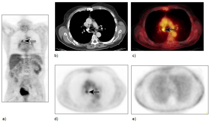
A 64-year-old male with a history of a left-sided primary squamous cell carcinoma of the lung referred for a staging PET/CT exam. The CT of the chest shows a calcified contralateral right paratracheal node appearing to have elevated FDG uptake on the AC PET images (Figure 1); however, the activity is absent on the non-AC images. Without inspection of the non-AC images, misinterpretation of the contralateral node as positive would have staged the patient as stage IIIB, with probable non-surgical management. No other abnormal lymph nodes were identified and there were no metastatic lesions. At mediastinoscopy, these nodes had only anthracotic material and no malignant cells, suggesting the minimal activity on the non-AC image to be the result of resolving inflammation from granulomatous disease.
Figure 1.
Calcified lymph node with AC artifact in a 64-year- old male with a history of left-sided primary squamous cell carcinoma of the lung referred for a staging PET/CT exam. Scan was performed 60 minutes after injection of 12–16 mCi of FDG tracer, with the following parameters: 120 kVp, 250mAs, 5 mm slice thickness, and CT based attenuation correction algorithm using two iterations and 8 subsets. Coronal AC PET image (a) shows a focal area of intense FDG uptake in the inferior right paratracheal area (arrow). Axial CT and fused axial PET/CT images (b,c) show the area of uptake to correspond to a calcified right paratracheal lymph node (arrows) (HU: min 365, max 3017, mean 2526). The non-AC axial PET image (e) shows minimal FDG activity in suspected area, as compared to the attenuation corrected image (d), and therefore is most likely an AC artifact superimposed on minimal inflammatory uptake from prior inflammatory disease. At mediastinoscopy, this node was histologically proven to be inflammatory.
Case 2
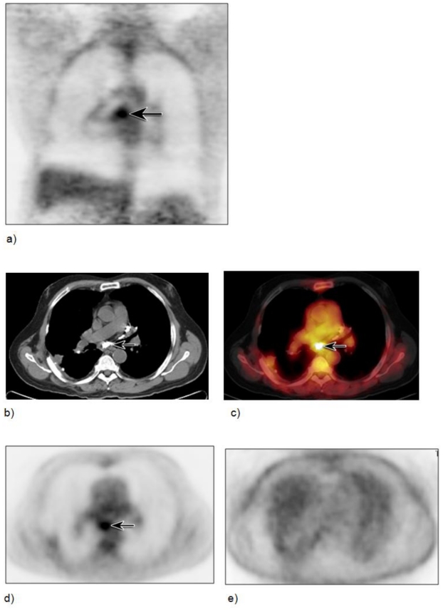
The patient is a 69-year-old male with a history of primary esophageal carcinoma with localized disease, who underwent esophagectomy, and is now referred for a six-month follow up PET/CT. Multiple calcified mediastinal and subcarinal lymph nodes are present and the subcarinal lymph node has intense apparent FDG uptake on the AC images (Figure 2), with no activity on the non-AC images, confirming the diagnosis of an AC artifact due to dense calcium within the node.
Figure 2.
Calcified lymph node with AC artifact in a 69-year-old male with a history of primary esophageal carcinoma with localized disease having undergone esophagectomy and was now referred for a six-month follow up PET/CT scan. Scan was performed 60 minutes after injection of 12–16 mCi of FDG tracer, with the following parameters: 120 kVp, 280mAs, 5 mm slice thickness, and CT based attenuation correction algorithm using two iterations and 8 subsets. Coronal AC PET image (a) shows a focal area of intense FDG uptake in the subcarinal area (arrow). Axial CT and fused axial PET/CT images (b,c) show the area of uptake to correspond to a large calcified subcarinal lymph node (arrows) (HU: min 435, max 1766, mean 1073). The non-AC axial PET image (e) shows no evidence of FDG activity in the suspected area proving the area to be an AC artifact, as compared to the attenuation corrected image (d).
Case 3
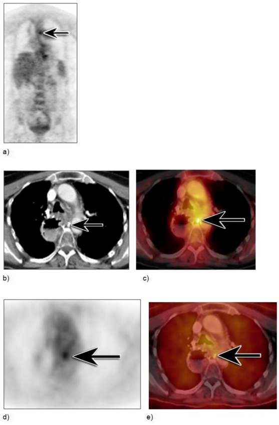
The patient is a 66-year-old female with a history of esophageal carcinoma, status post esophagectomy, with local recurrence. She has had both chemotherapy and radiation and is now referred for restaging. CT of the chest with IV contrast shows an area of calcification in the right inferior paratracheal lymph node. The lymph node demonstrates apparent intense FDG activity (Figure 3), but no activity is identified on the fused non-AC image, compatible with an AC artifact.
Figure 3.
Calcified lymph node with AC artifact in a 66-year-old female with a history of esophageal carcinoma, status post esophagectomy, with local recurrence, who had both chemotherapy and radiation and is now referred for restaging. Scan was performed 60 minutes after injection of 12–16 mCi of FDG tracer, with the following parameters: 120 kVp, 280mAs, 5 mm slice thickness, and CT based attenuation correction algorithm using two iterations and 8 subsets. Coronal AC PET image (a) shows a focal area of intense FDG uptake between the aorta and mid-thoracic vertebral body (arrow). Axial CT and fused axial PET/CT images (b,c) show the area of uptake to correspond to a small calcified lymph node (arrows) (HU: min 514, max 1372, mean 992). The non-AC fused axial PET/CT image (e) shows no evidence of FDG activity in the suspected area proving the area to be an AC artifact, as compared to the attenuation corrected image (d).
Case 4
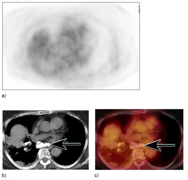
The patient is an 85-year-old female who was referred for a PET/CT after a CT scan of the chest showed a questionable soft tissue abnormality in the right hilum. The CT scan shows multiple calcified mediastinal and right perihilar lymph nodes which are not FDG avid and do not produce artifact, even though the node in the subcarinal area has large dense calcium within it (Figure 4).
Figure 4.
Large calcified lymph node without AC artifact in an 85-year-old female with questionable soft tissue abnormality in right hilum. Scan was performed 60 minutes after injection of 12–16 mCi of FDG tracer, with the following parameters: 120 kVp, 300mAs, 5 mm slice thickness, and CT based attenuation correction algorithm using two iterations and 8 subsets. Axial AC PET shows no FDG activity in the area of large subcarinal calcified lymph nodes, as seen on axial CT and AC axial fused PET/CT images (b,c) (HU: min 520, max 1371, mean 809).
DISCUSSION
Lymph nodes are encapsulated structures located throughout the lymphatic system composed of lymphoid cells and supporting tissue. The superficial nodes (cervical, axillary, and inguinal) drain the surface area of the skin, while deeper nodes, such as those in the mediastinum, mesentery, and intra-abdominal regions drain the lungs and the gastrointestinal tract. Calcified lymph nodes may have different configurations, including smooth, irregular, rough-edged, or a cauliflower appearance. Their size varies from a few millimeters to several centimeters.
Lymph node calcification is typically a marker of lymph node disease, with prior granulomatous disease being the most common etiology. However, both benign and malignant processes have been associated with lymph node calcification. Some of the benign causes include infectious etiologies such as histoplasmosis, tuberculosis, coccidioidomycosis and aspergillosis, and non-infectious causes such as silicosis and other benign inflammatory etiologies. Inflammatory lymph nodes exhibit a wide variability of appearances on PET/CT, ranging from mildly elevated FDG uptake to intense uptake that is indistinguishable from malignancy. The differential diagnosis for calcified lymph nodes also includes treated lymphoma, metastatic thyroid carcinoma, mucinous adenocarcinoma and rarely squamous cell carcinoma. Lastly, apparent FDG activity within a calcified lymph node could be due to an AC artifact. Fortunately, both benign and malignant causes of FDG activity within lymph nodes can easily be differentiated from artifactually elevated FDG activity by vigilant inspection of non-AC images. Therefore, we recommend inspection of the non-AC images in all patients, but particularly in any patient with a positive scan.
Interestingly, there appears to be no consistency to which calcified lymph nodes will cause an AC artifact, as demonstrated in case 4. It is unclear whether HU is the only variable determining whether there will be an AC artifact in a calcified node. In addition to scanner AC algorithm and HU within the node, other variables that may affect the incidence may include size, calcium content, or configuration and presence or absence of surrounding tissue with differential densities.
An AC artifact caused by a biological structure has only recently been described, with sclerotic osseous foci in two lumbar vertebral bodies mimicking metastases in a woman with breast carcinoma, as reported by Ho, et al (21). These authors also reported inconsistency in the appearance of the artifact despite apparently identical anatomy on the CT portion of the exam.
In conclusion, PET/CT scanners produce a number of unique AC artifacts including those caused by oral and intravenous contrast agents, prosthetic devices and other high-attenuation material. Many of these artifacts are easily recognizable due to their linear or typical appearances. However, atypical appearances of AC artifacts and less recognized AC artifacts, like calcified lymph nodes, may challenge even the experienced reader. The reason for the inconsistency of AC artifacts due to calcified lymph nodes remains unclear and further studies are warranted. Awareness of this commonly mistaken artifact is essential. Furthermore, careful inspection of non-AC images will eliminate misinterpretation and potential patient mismanagement due to calcified lymph node AC artifacts.
TEACHING POINT
Calcified lymph nodes can cause attenuation correction artifacts on PET/CT imaging, and this artifact needs to be considered as a potential cause of apparent FDG activity when calcified lymph nodes are present on the CT portion of a PET/CT study in order to avoid misinterpretation and potential patient mismanagement. Therefore, we recommend inspection of the non-AC images in all patients, but particularly in any patient with a positive scan.
ABBREVIATIONS
- AC
Attenuation correction
- CT
Computed tomography
- FDG
Fluorodeoxyglucose
- PET
Positron emission tomography
REFERENCES
- 1.Kinahan PE, Townsend DW, Beyer T, Sashin D. Attenuation correction for a combined 3D PET/CT scanner. Med Phys. 1998 Oct;25(10):2046–53. doi: 10.1118/1.598392. [DOI] [PubMed] [Google Scholar]
- 2.Burger C, Goerres G, Schoenes S, Buck A, Lonn AH, Von Schulthess GK. PET attenuation coefficients from CT images: experimental evaluation of the transformation of CT into PET 511-keV attenuation coefficients. Eur J Nucl Med Mol Imaging. 2002 Jul;29(7):922–7. doi: 10.1007/s00259-002-0796-3. [DOI] [PubMed] [Google Scholar]
- 3.Yau YY, Chan WS, Tam YM, Vernon P, Wong S, Coel M, et al. Application of intravenous contrast in PET/CT: does it really introduce significant attenuation correction error. J Nucl Med. 2005 Feb;46(2):283–91. [PubMed] [Google Scholar]
- 4.Blodgett TM, Fukui MB, Snyderman CH, Branstetter BFt, McCook BM, Townsend DW, et al. Combined PET-CT in the head and neck: part 1. Physiologic, altered physiologic, and artifactual FDG uptake. Radiographics. 2005 Jul-Aug;25(4):897–912. doi: 10.1148/rg.254035156. [DOI] [PubMed] [Google Scholar]
- 5.Beyer T, Antoch G, Bockisch A, Stattaus J. Optimized intravenous contrast administration for diagnostic whole-body 18F-FDG PET/CT. J Nucl Med. 2005 Mar;46(3):429–35. [PubMed] [Google Scholar]
- 6.Bockisch A, Beyer T, Antoch G, Freudenberg LS, Kuhl H, Debatin JF, et al. Positron emission tomography/computed tomography--imaging protocols, artifacts, and pitfalls. Mol Imaging Biol. 2004 Jul-Aug;6(4):188–99. doi: 10.1016/j.mibio.2004.04.006. [DOI] [PubMed] [Google Scholar]
- 7.Beyer T, Antoch G, Muller S, Egelhof T, Freudenberg LS, Debatin J, et al. Acquisition protocol considerations for combined PET/CT imaging. J Nucl Med. 2004 Jan;45(Suppl 1):25S–35S. [PubMed] [Google Scholar]
- 8.Antoch G, Freudenberg LS, Egelhof T, Stattaus J, Jentzen W, Debatin JF, et al. Focal tracer uptake: a potential artifact in contrast-enhanced dual-modality PET/CT scans. J Nucl Med. 2002 Oct;43(10):1339–42. [PubMed] [Google Scholar]
- 9.Antoch G, Kuehl H, Kanja J, Lauenstein TC, Schneemann H, Hauth E, et al. Dual-modality PET/CT scanning with negative oral contrast agent to avoid artifacts: introduction and evaluation. Radiology. 2004 Mar;230(3):879–85. doi: 10.1148/radiol.2303021287. [DOI] [PubMed] [Google Scholar]
- 10.Nehmeh SA, Erdi YE, Kalaigian H, Kolbert KS, Pan T, Yeung H, et al. Correction for oral contrast artifacts in CT attenuation-corrected PET images obtained by combined PET/CT. J Nucl Med. 2003 Dec;44(12):1940–4. [PubMed] [Google Scholar]
- 11.Cohade C, Osman M, Nakamoto Y, Marshall LT, Links JM, Fishman EK, et al. Initial experience with oral contrast in PET/CT: phantom and clinical studies. J Nucl Med. 2003 Mar;44(3):412–6. [PubMed] [Google Scholar]
- 12.Dizendorf EV, Treyer V, Von Schulthess GK, Hany TF. Application of oral contrast media in coregistered positron emission tomography-CT. AJR Am J Roentgenol. 2002 Aug;179(2):477–81. doi: 10.2214/ajr.179.2.1790477. [DOI] [PubMed] [Google Scholar]
- 13.DiFilippo FP, Brunken RC. Do implanted pacemaker leads and ICD leads cause metal-related artifact in cardiac PET/CT. J Nucl Med. 2005 Mar;46(3):436–43. [PubMed] [Google Scholar]
- 14.Halpern BS, Dahlbom M, Waldherr C, Yap CS, Schiepers C, Silverman DH, et al. Cardiac pacemakers and central venous lines can induce focal artifacts on CT-corrected PET images. J Nucl Med. 2004 Feb;45(2):290–3. [PubMed] [Google Scholar]
- 15.Kamel EM, Burger C, Buck A, von Schulthess GK, Goerres GW. Impact of metallic dental implants on CT-based attenuation correction in a combined PET/CT scanner. Eur Radiol. 2003 Apr;13(4):724–8. doi: 10.1007/s00330-002-1564-2. [DOI] [PubMed] [Google Scholar]
- 16.Goerres GW, Ziegler SI, Burger C, Berthold T, Von Schulthess GK, Buck A. Artifacts at PET and PET/CT caused by metallic hip prosthetic material. Radiology. 2003 Feb;226(2):577–84. doi: 10.1148/radiol.2262012141. [DOI] [PubMed] [Google Scholar]
- 17.Goerres GW, Schmid DT, Eyrich GK. Do hardware artefacts influence the performance of head and neck PET scans in patients with oral cavity squamous cell cancer. Dentomaxillofac Radiol. 2003 Nov;32(6):365–71. doi: 10.1259/dmfr/77741718. [DOI] [PubMed] [Google Scholar]
- 18.Bujenovic S, Mannting F, Chakrabarti R, Ladnier D. Artifactual 2-deoxy-2-[(18)F]fluoro-D-glucose localization surrounding metallic objects in a PET/CT scanner using CT-based attenuation correction. Mol Imaging Biol. 2003 Jan-Feb;5(1):20–2. doi: 10.1016/s1536-1632(03)00037-4. [DOI] [PubMed] [Google Scholar]
- 19.Goerres GW, Hany TF, Kamel E, von Schulthess GK, Buck A. Head and neck imaging with PET and PET/CT: artefacts from dental metallic implants. Eur J Nucl Med Mol Imaging. 2002 Mar;29(3):367–70. doi: 10.1007/s00259-001-0721-1. [DOI] [PubMed] [Google Scholar]
- 20.Cohade C, Osman M, Marshall L, Wahl RL. Metallic object artifacts on PET/CT: clinical and phantom studies. J Nucl Med. 2002;(43):308. [Google Scholar]
- 21.Ho L, Seto J. Attenuation artifact from sclerotic bone can mimic active bone metastasis on PET-CT. Clin Nucl Med. 2006 Nov;31(11):724–6. doi: 10.1097/01.rlu.0000242689.62045.50. [DOI] [PubMed] [Google Scholar]


