

Abstract
In normal individuals, the vestibular labyrinths sense head movement and mediate reflexes that maintain stable gaze and posture. Bilateral loss of vestibular sensation causes chronic disequilibrium, oscillopsia, and postural instability. We describe a new multichannel vestibular prosthesis (MVP) intended to restore modulation of vestibular nerve activity with head rotation. The device comprises motion sensors to measure rotation and gravitoinertial acceleration, a microcontroller to calculate pulse timing, and stimulator units that deliver constant-current pulses to microelectrodes implanted in the labyrinth. This new MVP incorporates many improvements over previous prototypes, including a 50% decrease in implant size, a 50% decrease in power consumption, a new microelectrode array design meant to simplify implantation and reliably achieve selective nerve-electrode coupling, multiple current sources conferring ability to simultaneously stimulate on multiple electrodes, and circuitry for in vivo measurement of electrode impedances. We demonstrate the performance of this device through in vitro bench-top characterization and in vivo physiological experiments with a rhesus macaque monkey.
Index Terms: neural engineering, semicircular canal implant, sensory neural prosthesis
I. Introduction
In normal individuals, the two inner ear labyrinths modulate activity on afferent fibers within each vestibular nerve branch so as to provide the central nervous system with sensation of rotational head motion and gravitoinertial acceleration. Each labyrinth contains three mutually orthogonal semicircular canals (SCCs) to sense head rotation and two otoconial endorgans (the utricle and saccule) to sense gravitoinertial acceleration. Each SCC is approximately coplanar, but antiparallel, with an SCC in the opposite ear, and each senses both ipsilateral and contralateral rotation. Input from coplanar pairs of SCCs is combined by neural circuitry that effectively computes differential mode signals, thus partially linearizing responses and defining a 3-dimensional (3D) coordinate system. When the head is oriented to align the horizontal SCCs with Earth horizontal, the SCC axes of rotation can be approximated by the “horizontal” axis (an Earth-vertical axis describing rotation within the horizontal plane) and the left-anterior/right-posterior (LARP), and right-anterior/left-posterior (RALP) a × es [1]. Mechanoreceptive hair cells embedded in each SCC’s sensory neuroepithelium modulate activity on that SCC’s ampullary nerve (one of five vestibular nerve branches) to encode the component of 3D head angular velocity about that SCC’s axis [2].
Vestibular sensory input drives compensatory reflexes that stabilize gaze and posture so as to maximize clarity of vision during head movement and to prevent falls. The angular vestibulo-ocular reflex (aVOR) stabilizes vision by generating compensatory eye movements based on 3D head rotation. The aVOR drives eye movement responses at very short latency (e.g., ~6 ms in rhesus monkeys [3]). Because the 3D axis of aVOR responses normally aligns with the 3D axis of head rotation, measurement of 3D eye movements provides a useful assay of the relative degree of excitation on different ampullary nerves (if otoconial and contralateral ear input remain constant and oculomotor function is intact).
Individuals who have bilateral loss of vestibular hair cell function can suffer disabling loss of visual acuity and balance. While compensatory use of visual and proprioceptive input can partially supplant lost labyrinthine input, this strategy fails during high frequency, high acceleration, transient head motions, such as those experienced while walking [2]. Approximately 0.1% of U.S. adults report a constellation of symptoms consistent with severe bilateral vestibular hypofunction, corresponding to about 200,000 individuals in the U.S. alone [4]. For those who fail to compensate through rehabilitation exercises, no adequately effective treatment exists. A multichannel vestibular prosthesis that modulates activity of surviving vestibular afferent fibers based on motion sensor input could improve quality of life for vestibular-deficient individuals.
Gong and Merfeld described the first head-mounted vestibular prosthesis in 2000 [5;6]. That device senses head rotation about one axis and electrically stimulates the vestibular nerve via implanted electrodes intended to excite afferents in an ampullary nerve innervating one SCC. Using this device, Gong, Merfeld et al. were able to partially restore the aVOR about one axis in monkeys and guinea pigs [5–11].
Della Santina et al.[12;13] described a multichannel vestibular prosthesis (here denoted MVP1, for Multichannel Vestibular Prosthesis, version 1) able to sense angular velocity about three orthogonal axes and asynchronous stimulate each of the three ampullary nerves of a labyrinth, allowing partial restoration of aVOR responses for head rotation about any axis. They noted two key challenges: (1) current spread to nontarget nerve branches results in misalignment of aVOR responses, and (2) reduction in device thickness and power consumption were needed prior to clinical application.
Phillips et al.[14], Shkel et al.[15], and Constandinou et al.[16;17] have described efforts to develop vestibular prosthesis circuitry. Phillips et al.[14] modified a commercially-available cochlear implant for use as a vestibular prosthesis. Although that device had no motion sensors, Phillips et al. demonstrated eye movements in response to stimuli and explored the possibility of using the device to pace nerve activity during episodes of vertigo. Shkel et al.[15] described a microelectromechanical system (MEMS) gyro and a circuit meant to emulate normal SCC dynamics described by Baird et al.[18]. Constandinou et al.[16;17] described an Application Specific Integrated Circuit intended for integration into a vestibular prosthesis. Neither Shkel et al. nor Constandinou et al. have reported in vivo results.
All prosthetic vestibular nerve stimulation studies to date have encountered performance constraints due to non-ideal electrode-nerve coupling and selectivity, as well as limitations related to number of channels, size and power consumption. In this report, we describe a new vestibular prosthesis prototype (here denoted the MVP2) that addresses many limitations of previous devices. The new device occupies less space, consumes less power, measures 3D rotation and linear acceleration, delivers multipolar stimuli via multiple independent current sources, and incorporates circuitry for wireless control and in situ measurement of electrode impedances. The MVP2’s smaller size and lower power consumption will facilitate chronic studies in animals necessary to lay a solid foundation for clinical trials of a vestibular prosthesis that restores 3D sensory input to individuals disabled by loss of vestibular hair cell function.
II. Device Description
A. System Design
Figure 1, the MVP2 detects 3D motion using MEMS gyroscopes and linear accelerometers. Sensor outputs are simultaneously sampled every 10 ms by a microcontroller, (MCU) which controls timing of stimulus pulse trains delivered via an array of electrodes switched under software control. Each pulse is biphasic and charge-balanced, with current amplitudes of 0 to 1 mA and pulse durations of 25 µs to 1,000 µs. The microcontroller controls 4 pairs of current sources and an analog switching network that can route stimulus currents from any 4 anodic electrodes to any 4 cathodic electrodes, allowing multipolar stimulation paradigms or simultaneous stimulation on up to 4 bipolar electrode pairs chosen from 12 electrodes and 2 references.
Fig. 1.

(A) MVP2 Circuit Schematic. The microcontroller reads sensor inputs every 10ms, then pulse-frequency-modulates biphasic charge-balanced pulses one each of six channels (one for each component of 3D rotation and linear acceleration). Two power supplies, +3V and +12V, are generated from a 3.7V Li-ion battery. Four current sources (B) and four current sinks (C) are connected to electrodes via a crosspoint switch array. An Electrode Potential Amplifier (D) can connect to any pair of electrodes; its output is read by the microcontroller. Gray lines = digital. Black lines = analog.
The MVP2 circuitry is built on two sides of a 6-layer 29 mm × 29 mm × 5.3 mm printed circuit board (Figure 2) using surface-mount technology. The weight of the completed device without battery, housing or wireless interface circuitry is 3.5 g. Under typical use conditions, the MVP2 draws 16.7 mA at 3.7 V and can operate for 14 hours on a single-cell Li-ion rechargeable battery shaped like an AAA battery.
Fig. 2.

Comparison of the original (MVP1) and new (MVP2) multichannel vestibular prostheses. The height/thickness of MVP2 is less than half that of MVP1, mainly due to replacement of single-axis gyroscope daughter boards with a flush-mounted dual axis gyroscope.
B. Sensors
For detecting 3D rotational velocity, the MVP2 uses a yaw-axis angular rate sensor (LISY300AL, STMicroelectronics, Geneva, Switzerland) and a dual-axis roll/pitch gyroscope (IDG300, InvenSense, Sunnyvale, CA). A tri-axial linear accelerometer (ADXL330, Analog Devices, Norwood, MA) senses 3D gravitoinertial acceleration. As pictured in Figure 2, the IDG300 is positioned flush on the board and offset 45° from the ADXL330, so that when the latter is aligned with the antero-posterior (X, +nasal), inter-aural (Y, +left) and superoinferior (Z, +up) head axes, the gyro directly senses rotation components about the LARP and RALP SCC axes. Sensors used in the MVP2 yield significant improvement in size, power consumption and function compared to the MVP1. The MVP2 circuitry’s thickness is reduced to 5.3 mm (<50% of MVP1) by replacement of single-axis gyroscopes that were mounted on upright daughter boards in the MVP1. MVP2 total sensor power consumption is 44 mW, less than 50% of the MVP1’s gyros. Reductions in size and power use are achieved despite addition of tri-axis linear acceleration sensing.
C. Processor
The MVP2’s 8 MHz MSP430F1611 microcontroller (Texas Instruments, Austin, TX) incorporates a 16-bit RISC architecture with 10-kB of RAM, 48-kB of flash memory, eight 12-bit analog-digital converters (ADCs), flexible timing mechanisms, low power modes, and two serial communication interfaces (UART and I2C) in a small package (9×9×1 mm3). The analog-digital converters are used to sample gyroscopes, accelerometers, and potential differences between any two electrodes. The timer module provides up to seven independent timers operating at 32,768 Hz (which schedule ADC sampling and control pulse rate timings in the MVP2) and three timers operating at 8 MHz (to control fine timing of biphasic current pulses). To deliver a stimulation pulse, the microcontroller first sets the amplitude of voltage controlled current sources and then assigns two or more electrodes via I2C commands issued to a crosspoint switch array. Between stimulus pulse transitions, the microcontroller is toggled to a low power mode in which it consumes 330 µA between events. When fully active, it draws 4 mA from a 3V regulated supply.
D. Current Source and Switching
The MVP2 can simultaneously control current amplitudes on up to four anodic electrodes (using 4 current sources) and up to four cathodic electrodes (using 4 current sinks). Current sources sinks are multiplexed through analog switches (ADG2128-HS, Analog Devices, Norwood, MA and ISL43145, Intersil, Milpitas, CA), under software control, to any combination of electrodes. The second phase of each biphasic pulse is created by swapping the sources and sinks used to create the first pulse phase.
An AD5346 octal digital-to-analog converter (Analog Devices, Norwood, MA) sets voltages that indicate the desired current for each current source (Figure 1B) and sink (Figure 1C). All current sources and sinks can output current amplitudes in the range of 0 to 1 mA with a resolution of 3.9 µA (256 levels). A compliance voltage of +12V generated from a 3.7V battery by a step-up converter (LT1615, Linear Technology, Milpitas, CA), ensures that current sources can deliver desired current through each electrode pair’s typical ~20–40 kΩ series impedance.
E. Electrical Potential Amplifier
The electrode potential amplifier (EPA, Figure 1D) is comprised of one stage of an instrumentation amplifier (AD8224, Analog Devices, Norwood, MA). The EPA’s two inputs can connect to any electrode pair through the crosspoint switch under software control. An amplifier gain of 1/8 and output DC offset of 1.5 V ensure that the maximum biphasic pulse amplitude possible can be directed into the microcontroller’s ADC inputs without causing damage. The MCU can sample EPA output at up to 200-kSamples/s and/or transmit data to an external computer for display and analysis.
F. Control Algorithms and Software
We programmed the MVP2 using the Embedded Workbench (IAR Systems AB, Uppsala, Sweden), and a flash emulation tool through the MCU’s JTAG interface. MVP2 control code is organized around three timer-driven interrupt service routines: (1) a Parameter-Set routine allowing in situ adjustment of device parameters via a user interface; (2) a Sample/Update routine to continually update each stimulus channel’s pulse rate based on motion sensor inputs; and (3) a Fine-Timing routine to generate each biphasic pulse.
The Parameter-Set routine is used to adjust device parameters in situ. This service routine is triggered upon reception of a single UART byte (baud rate: 38,400 bps, 8 bits per byte, 1 stop bit, odd-parity), which is placed in the Parameter-Set queue. With each byte entered into the queue, the routine searches for a coherent command string. The coherent command string is encoded as follows: (1) a command byte, (2) a byte indicating length of subsequent data, (3) data byte(s), and (4) a check-sum byte. If the check-sum calculation passes, the appropriate parameter is changed to the value indicated in the data byte(s), and an Acknowledge byte is sent by the microcontroller. If a parity, check-sum, or time-out failure occurs, the queue is erased and transmission restarts. This Parameter-Set routine was tested continuously for 3 days at a rate of 400 commands/sec with no failures.
The Sample/Update routine initiates ADC conversion every 10 ms for each stimulation channel. After preprocessing raw sensor signals via time-domain filtering, the routine converts each component of head motion into a new instantaneous pulse rate for each motion sensor channel. Similar to the head-velocity-to-pulse-rate mapping used in MVP1 [13], the MVP2 sets a “time-until-next-pulse” parameter for each stimulation channel based on the each gyro’s output using a 32-segment piecewise-linear approximation to a sigmoid curve defined by
where f is the output pulse rate, fmax is the peak pulse rate, fbase is the baseline stimulation rate for zero velocity, C determines the slope of the pulse rate versus head velocity curve about the baseline rate, and xi is the 12-bit ADC input ranging from 0 (corresponding to 500°/s head rotation toward the implanted labyrinth) to 4095 (500°/s away), with 2048 corresponding zero head velocity. This ADC mapping corresponds to 0.24°/s per least significant bit (LSB) providing a resolution comparable to normal SCCs. A 32 bin look-up table of slopes and intercepts facilitates efficient calculation of this nonlinear mapping function in a compromise between computational time and memory use. Six individualized tables (one for each of six motion sensors) occupy 768 bytes in flash memory; updating “time-until-next-pulse” parameters for all six channels requires 222 µs.
For the physiologic data presented below, we used velocity-to-frequency maps on all gyro channels designed to emulate the normal behavior of rhesus vestibular primary afferent (fbase=100 pulse/s, fmax=350 pulse/s, C=2; based on [3]), then optimized electrode currents, pulse durations and channel assignments iteratively, first defining thresholds (at which eye movements are first observed) and maximal levels at which signs of current spread occur (large eye movement axis changes and facial nerve stimulation), then specify a parameter set within that range. We have previously described the dependence of eye movement responses and alignment on stimulus amplitudes and timing in detail [19], as well as a vector precompensation (i.e., orthogonalization) algorithm for reducing misalignment of prosthetically-evoked eye movement responses [20]. No vector precompensation was employed during acquisition of the in vivo data presented below.
The Fine-Timing routine generates each biphasic pulse. To accommodate short pulse durations, this interrupt service routine is clocked at 8 MHz. It initiates whenever a stimulation channel’s "time-until-next-pulse" timer reaches zero, then steps through each of 4 states (state 1: cathodic phase, state 2: interphase interval, state 3: anodic phase, state 4: ‘available’). Each state sets the user-defined phase duration, current amplitudes for each of the current source/sinks, and electrodes to which each the current source/sink connects, increments the state by one, and puts the microcontroller in a low-power mode until the duration for that state is reached. When state 4 is reached, the state variable is set to ‘available’ and other channels are allowed to flag this routine.
G. Electrode Array
Unlike the MVP1, for which electrodes were fashioned from twisted pairs of wires that were difficult to reliably place individually near each SCC’s ampullary nerve, electrode arrays designed and fabricated for the MVP2 are much more like those of cochlear implants currently in clinical use. Based on species-specific microanatomic measurements from 3D reconstructions of CT images of existing temporal bone specimens for normal rhesus macaque monkeys, each electrode array comprises 9 active and 2 reference electrodes, with active electrodes partly embedded within a silicone carrier (Figure 3). All electrode pads and wires are 90/10 platinum/iridium alloy.
Fig. 3.

MVP2 electrode array designed using 3D reconstructions of CT images of a rhesus monkey labyrinth. Surgical implantation into the three semicircular canals (SCCs) is facilitated by manipulation of two silicone carriers, one that positions 6 electrodes (E4-9) within the anterior and horizontal ampullae and a second that positions E1-3 in the posterior SCC ampulla. Having multiple electrodes near each ampullary nerve allows post-surgical adjustment of nerve-electrode coupling under software control. The microelectrode array has two reference electrodes: a large-area distant reference (E10) and a smaller return electrode meant for insertion at the common crus of the vestibular labyrinth (E11).
The new electrode arrays simplify surgical implantation because they allow precise microsurgical placement of nine active electrodes via manipulation of only two silicone carriers. The carriers are shaped to self-orient within each implanted ampulla so that electrodes rest adjacent to target ampullary nerve endings. One silicone carrier is shaped like a fork to facilitate the placement of electrodes within the ampullae of the horizontal and superior SCCs, while the other carrier is designed to be inserted into the posterior ampulla. Each carrier includes three electrodes per ampullary nerve target separated by a fixed 200 µm distance between adjacent electrodes. Having multiple electrode contacts per ampullary nerve target reduces the risk of missing the target tissue.
The two reference electrodes allow two possible paths for flow of stimulus current. One reference electrode is typically inserted far from the labyrinth, beneath the temporalis muscle. A second reference electrode consists of an electrode wire inserted into the perilymphatic space of the common crus (i.e., the common segment of the anterior and posterior SCCs).
The crosspoint switch array can connect any of 4 current sources or 4 sinks to any electrode under software control, allowing many possible stimulation paradigms, including: (1) “monopolar” stimulation via one labyrinthine electrode to a distant reference; (2) “bipolar” stimulation between two neighboring labyrinthine electrodes; and (3) “multipolar” combinations of up to four anodes and up to four cathodes. This flexibility facilitates targeting of each nerve branch.
III. Experimental Methods for in vivo Tests
A. Surgery
An adult rhesus macaque (Macaca mulatta) was used for in vivo tests of the MVP2. Surgical procedures were conducted in accordance with a protocol approved by the Johns Hopkins Animal Care and Use Committee. Our methods for surgical implantation of a head-fixation unit and scleral coils for magnetic search coil recording of 3D eye movements in primates have been described in detail previously [21–23]. A light phenolic head cap was affixed to the skull under sterile conditions using titanium bone screws and poly-methyl methacrylate. Two search coils were fashioned from Teflon-coated steel wire (Cooner Wire, Chatsworth, CA) and sutured to the sclera of one globe, with one around the iris and the other approximately orthogonal to the first. Wires were tightly twisted to reduce inductive artifacts and then run to connectors within the head cap. Animals were maintained under general anesthesia for surgery and treated with analgesics and antibiotics for 72 hours perioperatively.
An electrode array was implanted into the left labyrinth via a transmastoid approach analogous to that used for cochlear implantation. Under sterile conditions, a mastoidectomy was performed. The junction of the ampullae of the superior and horizontal SCCs was identified, and two small holes were made there, keeping a thin strut of bone intact between the two to serve as a stop when inserting the forked electrode array. An opening was also made in the thin segment of the posterior SCC near its junction with the ampulla, into which the single-tine electrode array was inserted. Pieces of fascia were tucked around each array, and a small amount of dental cement (Protemp ESPE, 3M Corp) was used to stabilize the electrode leads, which were run under periosteum to the head cap.
Intratympanic gentamicin was administered using a standard clinical dosing regimen: ~0.5 mL of buffered gentamicin solution (26.7 mg/mL) was instilled into each middle ear, with the animal kept under general anesthesia for 30 minutes with the treated ear up after each injection. Treatments were repeated each three weeks until VOR responses to head rotation reduced to <10% of normal gain, which in this case required two injections per ear.
B. Benchtop Tests of Prosthesis Performance
To test the MVP2’s ability to modulate pulse rates based on the input from its gyroscopes and linear accelerometers, we examined outputs while the prosthesis rotated atop a servo-controlled Earth-vertical-axis rotator (Acutrol ACT 2000, Acutronic, Pittsburgh, PA). We measured instantaneous pulse rates on all channels as they were modulated by signals from the six motion sensors. For gyroscopic measurements, the prosthesis was rotated sinusoidally at 50°/s peak, 1 Hz in the yaw, roll, and pitch axes. To test pulse rate modulation by linear acceleration, the prosthesis was secured 20 cm away from the center of the rotator and oriented so each linear accelerometer would measure one of the following signals: (1) Earth-vertical gravitational acceleration; (2) a sinusoidally-modulated centripetal acceleration; or (3) a sinusoidally-modulated tangential acceleration.
C. Vestibulo-ocular Reflex in Response to Rotation
We recorded eye movements in darkness during 2 Hz, 50°/s peak whole body rotation about each SCC axis for a rhesus macaque monkey fitted with an actively modulating prosthesis for 3 days of continuous use prior to the measurement. Prosthesis stimulation map parameters (see Sect. IIF) were fbase=100 pulse/s, fmax=350 pulse/s, C=2, and 200 µs/phase for each gyro/SCC stimulator channel; linear accelerometer inputs were not used; and current amplitudes were 180, 65 and 180 µA/phase for the horizontal stimulating electrode pair (E7–E11 in Fig. 3), anterior pair (E6–E11) and posterior pair (E2–E11), respectively. The eye coil system we used to measure 3D angular eye position has been described in detail previously [21–23]. Briefly, the animal was seated in a plastic chair with its head restrained by the skull cap. The chair was mounted within a Fick gimbal connected to a servo-controlled Earth-vertical-axis rotator with peak torque of ~375 Nm (Acutronic). The gimbal allowed us to reorient the animal to align any SCC axis with that of the rotator. Three pairs of field coils were rigidly attached to the superstructure and moved with the animal, generating three fields orthogonal to each other and aligned with the X (nasooccipital), Y (interaural), and Z (superoinferior) head coordinate axes. The X, Y and Z fields oscillated at 79.4, 52.6 and 40.0 kHz respectively. The three frequency signals induced across each scleral coil were demodulated [24] to produce three voltages proportional to the angles between the coil and each magnetic field, then analyzed using 3D rotational kinematic methods detailed by Straumann et al.[25]. All signals transducing motion of the head or the eye were passed through eight-pole Butterworth anti-aliasing filters with a corner frequency of 100 Hz prior to sampling at 200 Hz. Coil misalignment was corrected using an algorithm that calculated the instantaneous rotation of the coil-pair with reference to its orientation when the eye was in a reference position [26]. Angular rotations were expressed as rotation vectors with roll, pitch, and yaw coordinates [27;28], and angular velocity vectors of eye with respect to head were calculated from the corresponding rotation vectors [29]. Angular position resolution of the coil system was 0.2° (tested over the angular range of ±25° combined yaw, pitch, and roll positions), and angular velocity noise was ~2.5°/s peak.
D. Electrode Impedance measurements
By measuring potential across the series combination of a small labyrinthine electrode and much larger reference during a constant-current pulse, the smaller electrode’s impedance can be determined. Using this approach, we measured impedance for each of the 10 intralabyrinthine electrodes with respect to the large reference electrode implanted beneath the temporalis muscle (E10). In each case, we used constant current, biphasic, charge-balanced pulses with current amplitude of 150 µA/phase and pulse duration of 200 µs/phase. Sixteen stimulation pulses for each electrode were averaged to eliminate noise. EPA output was sampled both by the microcontroller and by a digital oscilloscope with isolated inputs (TPS2024, Tektronix), which simultaneously measured potential across the electrode pair. We estimated resistive (R) and capacitive (C) components of impedance for each of the electrodes from the instantaneous voltage change at pulse onset, and the voltage change in time during the first 200 µs pulse phase using , respectively.
E. Tripolar Stimulation
We designed the MVP2 with ability to perform multipolar stimulation (also termed "current steering"), which has been used in cochlear implants to selectively target specific nerve populations [30]. Although the MVP2 can stimulate between up to four cathodic current sources and up to four anodic current sinks, we tested the simplest case of one “stimulating” electrode near target tissue and two “return” electrodes.
Based on prior observations, we hypothesized that simultaneously returning stimulus current via two anodic reference electrodes – one extracranial and one intralabyrinthine in the common crus – might deform the current field around a single cathodic intralabyrinthine stimulating electrode sufficiently to yield improved aVOR alignment without sacrificing aVOR response amplitude. To test this hypothesis, we measured eye movement responses to varying distributions of current delivered by this tripolar configuration. The stimulating electrode was implanted in the left posterior SCC (E3 in Figure 3), one reference electrode was outside the ear beneath the temporalis (E10 on Figure 3), and the other was within the common crus of the left vestibular labyrinth (E11 on Figure 3). The total current passed via E3 into the left posterior SCC ampulla was 200 µA/phase for each trial, pulse duration was always 200 µs/phase, and stimulation map parameters were the same as described above. We varied α, the fraction of total current being returned via electrode E10 while E11 always returned [1 − α] * 200 µA/phase. The prosthesis was configured to internally modulate pulse rate to simulate a 300°/s peak, 1 Hz head rotation about the LP SCC. Peak-to-peak eye response amplitudes were quantified for each 10 s period during which a single α value was used. We repeated this for varying levels of α (from 0% to 100% in 10% increments), with the 0% and 100% cases equivalent to either standard “monopolar” stimulation (vs. distant reference E10) or “bipolar” stimulation (vs. near reference E11).
IV. Results
A. Bench-top Performance
Figure 4 demonstrates the device’s ability to modulate pulse rate based on sensor input. During yaw rotation, the prosthesis appropriately modulated pulse rate on the horizontal (Z channel) electrode. Pitch evoked anti-phase modulation on the LARP and RALP channels, and roll evoked in-phase modulation on those two channels. During off-axis rotations that evoked linear acceleration, electrodes assigned to the linear accelerometer outputs modulated appropriately with gravitational, tangential (at=r·dΩ/dt), and centripetal (ac=r·Ω2) acceleration, where Ω=angular velocity and r=20 cm.
Fig. 4.

(A) Pulse-frequency modulation of electrode pulse rates by gyroscope inputs. In each case, the appropriate channels modulate. Pitch and roll elicit the appropriate antiphase and in-phase responses, respectively, on left-anterior/right-posterior (LARP) and right-anterior/left-posterior (RALP) channels. Z denotes yaw channel. (B) When prosthesis is mounted 20 cm off the rotator axis, electrode channels temporarily set to encode gravitational acceleration, centripetal acceleration, and tangential acceleration modulate appropriately.
Some pulse rate irregularity is evident in each case. In the case of gyros, this is mostly due to pulse timing clashes, since the asynchronous, interrupt-driven pulse timing routines occasionally result in a given channel having to wait to deliver its pulse until other channels in the Fine Tuning routine’s stimulation pulse queue are cleared. The more pronounced irregularity relates to a combination of a small input signal (~0.22g pk-pk tangential acceleration), true vibrational acceleration of the motor, electronic noise injection at the sensor output, and a fairly high (~0.05g pk-pk) noise equivalent input due in part to a sensor bandwidth set for >100 Hz. The latter two of these could be reduced by changes in discrete filtering capacitors on the MVP2. Notably, pulse rate irregularity is a prominent feature of many vestibular afferent neurons [31] so some variability is not necessarily detrimental.
B. Performance in vivo
Activation of the prosthesis partially restored the 3D aVOR for a macaque rendered bilaterally vestibular-deficient via treatment with intratympanic gentamicin after 2 injections in each ear. Figure 5 shows mean head and eye angular velocities during head rotation in darkness about each of the three SCC axes prior to vestibular lesion, after implantation but with the prosthesis set to stimulate at baseline rates without modulation, and with the prosthesis modulating on all channels to encode gyro inputs using the stimulation parameters defined in Section IIIC. Although aVOR alignment in the latter case is not perfect, significant improvement in both aVOR gain and alignment is apparent for every head rotation axis examined.
Fig. 5.

Mean head and eye angular velocities of a macaque during 2 Hz, 50°/s head rotations in darkness, about the horizontal (top), left-anterior/right-posterior (LARP- middle) and right-anterior/left-posterior (RALP - bottom) SCC axes. Column 1: Prior to lesion. Column 2: After bilateral intratympanic gentamicin, plugging all SCCs, and electrode implantation in left labyrinth. Prosthesis pulsing at baseline rate on all channels, but not modulating with head rotation. Column 3: With prosthesis modulating to encode gyro signals, after 3 days of prosthetic stimulation. Standard deviation of each trace at each time point is < 10°/s. Traces are inverted about the zero velocity axis as required to facilitate comparison; first half cycle represents excitation of left labyrinth in each case. N=20 cycles for each trace. Blanks indicate removal of nystagmus quick phases, which occur as needed to return the eye toward center position.
During trials with the prosthesis on, a nystagmus quick phase was noted just after the peak of eye velocity in response to RALP head rotation (and thus during maximal excitation via the left posterior semicircular canal [LP SCC] electrode). Observing the animal using an infrared video camera revealed no blinks or other signs of facial nerve stimulation, and the quick phases appeared to be upward and counter-clockwise (from the monkey’s frame of reference), as would be expected during LP SCC excitation. This was consistently in the direction appropriate to restore the eye toward center position, as is typical of nystagmus quick phases. In fact, quick phases occurred for all three axes of head rotation tested and for both senses of rotation; however, there were enough cycles free of quick phases to construct continuous mean traces for the horizontal and LARP trials and for the second half-cycle of RALP responses. In contrast, every first half-cycle of the RALP data for this session included a quick phase, consistent with the relatively high gain of the RALP excitatory responses compared to inhibitory response (latter half-cycle in Figure 5, bottom right) and compared to responses for other head rotation axes. Factors determining the timing of quick phases are incompletely understood, but they probably involve time varying thresholds of eye position, velocity and acceleration that, when exceeded, trigger an aVOR-mediated compensatory eyes rotation in the direction opposite slow phase nystagmus.
Figure 6 shows impedances measured for each electrode with respect to the distant reference electrode E10 during the 150 µA, 200 µs biphasic current pulses. All voltage traces had similar waveforms. Mean resistive and capacitive components of electrode impedance were equivalent to 27.8 ± 1.9 kΩ (±SD) and 15.4 ± 1.5 nF. Electrode E11, the reference electrode positioned internal to the SCCs, had the highest capacitance of all electrodes, consistent with its greater lead length outside the silicone carrier.
Fig, 6.

Potential waveform and corresponding electrode impedances (inset) for each of 10 intralabyrinthine electrodes measured in series with a much larger distant reference (E10) using the EPA amplifier. Within each case, symmetric constant-current biphasic pulses were 150 µA peak and 200 µs per phase.
Figure 7 demonstrates the effect of “steering” current from one electrode in the left posterior SCC ampulla by returning different fractions via each of two different return electrodes in a tripolar configuration. Cathodic-first current pulses delivered via electrode E3 versus distant reference E10 alone (i.e., α =1, the typical “monopolar” configuration) elicited an aVOR eye responses at 136 ± 7.7°/s peak with misalignment (relative to the RALP axis) of 23 ± 2.7°. Stimuli delivered via E3 to near reference E11 (i.e., α = 0, a “bipolar” format) elicited a larger aVOR eye response of 209 ± 18°/s, but the misalignment was also greater at 33 ± 4°. For a subset of α values (0.5≥α≥0.7), it was possible to maintain response amplitude while minimizing misalignment. For comparison, the amplitude and misalignment of aVOR eye responses to RALP rotation in the Prosthesis OFF condition for the same animal (i.e., Figure 5, middle column, bottom panel) are indicated on Figure 7.
Fig. 7.
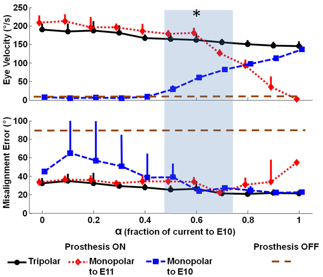
Eye movements in response to tripolar stimulation with varying proportions of a 200 µA/phase, 200 µs/phase, biphasic cathodic-first stimulus current pulse (via electrode E3 near the left posterior SCC) returned by either a distant reference (E10, square), near/intralabyrinthine reference (E11, diamond), or a proportional distribution between the two (circles). α = fraction of current returned via E10. During tests, the monkey was stationary in darkness, and the MVP2 was set to modulate pulse rate on E3 as required to simulate a 1 Hz, ±300 °/s sinusoidal head rotation about the LP SCC axis. Peak eye movement response amplitude and misalignment (angle between desired and observed 3D axis of aVOR eye response) were computed as the mean (±SD) for 10 cycles at each α. Asterisk indicates α’s at which amplitude was significantly better (p<0.01) than the α=1 case while misalignment was significantly less (p<0.01) than the α=0 case. For comparison, the dashed horizontal line indicates the peak velocity and misalignment of the eye response to RALP rotation with the prosthesis off (Figure 5 middle column, bottom row) showing the residual eye movement after gentamicin treatment without prosthetic stimulation.
V. DISCUSSION
In developing the MVP2, our goals were to reduce size and power consumption while enhancing function by adding ability to sense both rotational and linear motion, to stimulate using multipolar configurations, and to measure electrode impedances in situ.
Size and Power
While continued advances in manufacture of multi-axis MEMS sensors may allow further size reduction and improved noise performance, the MVP2 circuitry’s size is now comparable to that of cochlear implants that have remained in use for decades [32]. Reduction of device thickness to 5 mm (from the MVP1’s 11 mm) was essential to allow encapsulation in a package thin enough for subperiosteal implantation of the sensor array using a surgical approach analogous to cochlear implantation. The MVP2’s improved power consumption allows up to 50 hours of operation on three AAA-sized batteries in a package that is small, light and flat enough to fit within the head apparatus used for our rhesus macaque experiments. Since the rhesus monkey is able to tolerate the weight of the prosthesis and two days’ worth of batteries with little to no apparent change in behavior, we house the MVP2 and battery extracranially in a head cap and power the MVP2 through a percutaneous link. Transition to an inductive power link would obviate the percutaneous connection (making the device more like the current generation of cochlear implants), but incur a 75–80% overhead for power transmission across the skin.
Despite the MVP2’s nearly 50% reduction in power consumption versus the MVP1, its consumption is still high compared to existing cochlear implants, even before accounting for losses due to an inductive transcutaneous link. Since the motion sensors account for the great majority of the MVP2’s power consumption, improvements in inertial sensor power consumption driven by the consumer electronics industry are likely to facilitate continued improvement in performance with updated designs of MVP. If the rate of advances in gyroscope technology is consistent with the trend during development of the MVP1 (90 mW for triaxial sensing in 2006) and the MVP2 (45 mW for triaxial sensing in 2009), future MVP versions should eventually achieve power consumption compatible with a full day of use per discharge cycle of a rechargeable battery implanted with the device.
Responses to in vivo Stimulation
Data in Figure 5 confirm that the MVP2 is able to partially restore the 3D aVOR for head movements about each SCC axis in rhesus monkeys, albeit with some nonideal aspects of response including imperfect alignment with the 3D head rotation axis and relatively prominent excitation-inhibition asymmetry (e.g., difference in response magnitude for head rotations toward and away from the implanted labyrinth).
VOR response asymmetry probably reflects two factors. First, excitation-inhibition asymmetry is already a cardinal feature of aVOR responses driven by a single ear (even a normal one) during high intensity stimuli [33]. Second, asymmetry is increased in the setting of pulsatile prosthetic stimulation by the inability of an MVP to depress vestibular nerve primary afferent fibers’ firing rates below the fibers’ spontaneous discharge rates. This asymmetry can be reduced through adapting the central nervous system to supernormal baseline rates from which one can down-modulate; however, this usually incurs a cost in terms of reduced gain and reduced dynamic range for excitatory head rotations.
The phase lag in the horizontal Prosthesis ON case is about 35° (48 msec delay at 2 Hz). In contrast, the phase lag is about 18° (25 msec) for responses to LARP and RALP head rotations in the Prosthesis ON case. Although the Prosthesis ON response is clearly closer to normal than the Prosthesis OFF case (for which responses are too small to measure a phase lag), a 48 msec latency is longer than the latencies of normal responses, which are all less than 10 msec (fig. 5, first column). While a full characterization of physiologic responses to prosthetic stimulation is beyond the scope of this report, it is interesting to consider factors that might contribute to this latency: (1) The MVP2 was set for a 100 Hz gyro sampling rate, so from the onset of any head movement, the delay until the next time that gyros are sampled is random and uniformly distributed over 0–10 ms. (2) There is delay inherent in the normal vestibulo-ocular reflex; this is less than 10 msec (Fig 5 column 1). (3) Whereas normal animals can detect linear acceleration and jerk using saccular and utricular hair cells, a monkey treated with gentamicin bilaterally will have lost that ability. Even if the prosthesis recreates a perfect pattern of ampullary nerve activity to encode head rotation, absence of linear acceleration and jerk signals (which lead angular velocity) may incur result in longer response latency. (4) Whereas a normal animal probably uses population encoding over a large number of afferent neurons with different sensitivities to accurately encode head movement, the prosthesis probably engenders nearly a synchronous firing pattern on all neurons it activates within a given ampullary nerve. The consequent distortion of neural activity patterns reaching vestibular nuclei may interfere with the signal processing that normally occurs there.
Linear Accelerometry
We have not yet attempted to encode linear acceleration via stimulation of macular nerves, mainly due to the tight spacing of axons with different direction sensitivity within the utricle and saccule. Variations evident in the pulse rate modulation data of Figure 5 indicate that for that application, additional filtering and noise conditioning of the accelerometer signals would be necessary. In practice, we currently use the MVP2’s tri-axis linear accelerometer to measure the device’s orientation (at a resolution up to 0.139° in situ) with respect to palpable skull landmarks that can in turn be related to SCC orientations. This obviates the need for postoperative imaging to measure sensor orientation.
Multipolar stimulation
Ability to control several current sources concurrently offers a means to achieve better control over axis misalignment via “virtual electrode” and “current steering” paradigms analogous to those used with some cochlear implants [30]. Although the complexity of labyrinthine microanatomy makes it difficult to predict a priori exactly how an electrode’s response axis will change when different fractions of that electrode’s source current are steered to different returns in a tripolar paradigm, the data in Figure 7 confirm that a multipolar paradigm can shift the pattern of ampullary nerve stimulation sufficiently to reduce misalignment while maintaining response amplitude.
The tripolar configuration we chose differs from the approaches more commonly used in multipolar experiments employing cochlear implants [30]. In “virtual electrode” tripolar configurations used experimentally with cochlear implants, two “stimulating” electrodes adjacent to each other on a linear array in the scala tympani deliver different proportions of a total current that is typically returned by a single extracranial reference electrode. By adjusting the proportion of current injected by each intra-scalar electrode, one can systematically move the effective sound percept from the center frequency perceived with the first electrode alone (during “monopolar” stimulation vs the distant reference) to the center frequency of the second. In a second approach, all three electrodes are within the cochlea and very near each other, forming a tripolar current field that confines stimulation to a small region of nearby tissue.
To obtain the data in Figure 7, we used a third approach, with a single “stimulating” electrode near the target nerve (X=E3) and two “return” electrodes (Y=far reference E10; Z=near reference E11 in the common crus). In this configuration, changing α changed both the shape and spatial extent of the current field around E3 while maintaining the total current passing from the “stimulating” electrode E3. We chose this approach because our goal was to maintain large response amplitudes while altering the degree of misalignment by sculpting the current field emanating from E3. We have yet to characterize responses for each of the wide range of multipolar configuration possible with the MVP2.
In situ impedance measurement
Measurement of electrode impedances has proven useful in management of cochlear implants because it provides a means to monitor electrode integrity, movement and microenvironment [34]. The same circuitry can be adapted to measure neural population responses, providing information helpful for surgical guidance during electrode implantation or post-operative adjustment of stimulus parameters [35].
Future Directions
Despite improvements realized by the MVP2, much work remains to bring a completely functional multichannel vestibular prosthesis to successful clinical application, including continued refinement of circuitry, firmware, surgical technique, methods for characterization of electrically-evoked responses, electrode array design, and stimulus parameter optimization. Optimization of the surgical approach and placement of electrodes is important to minimize variation in nerve-electrode coupling due to variability in electrode location and orientation. Intra-operative measurement of electrically-evoked compound action potentials as the electrode is advanced towards the nerve could prove helpful in this regard [35]. Regarding device design, effort must be directed toward further miniaturization, reduction of power consumption, hermetic packaging, transcutaneous power delivery, and an implantable power source. Firmware refinement should benefit from continued progress on stimulus optimization [19] and algorithms for correction of misalignment [20]. The MVP2’s flexible architecture should facilitate these refinements through enabling both acute studies of different stimulus protocols and chronic studies to characterize long term outcomes.
Acknowledgments
We thank Manu Ben Johny for help with 3D measurements from rhesus macaque imaging datasets and Americo A. Migliaccio for creation of software we use for eye movement measurement and analysis. We also gratefully acknowledge the contributions of contractors Tom Mehl (printed circuit board layout) and Frank Risi (electrode fabrication).
This work was funded by the National Institute on Deafness and Other Communication Disorders (NIDCD) grants R01-DC009255, K08-DC006216 and R01-DC002390. Dr. Della Santina is is the founder and CEO of Labryinth Devices, LLC. The terms of this arrangement are being managed by the Johns Hopkins University in accordance with its conflict of interest policies.
Footnotes
Personal use of this material is permitted. However, permission to use this material for any other purposes must be obtained from the IEEE by sending a request to pubs-permissions@ieee.org
References
- 1.Della Santina CC, Potyagaylo V, Migliaccio AA, Minor LB, Carey JP. Orientation of human semicircular canals measured by three-dimensional multiplanar CT reconstruction. JARO. 2005 Sep.vol. 6(no. 3):191–206. doi: 10.1007/s10162-005-0003-x. [DOI] [PMC free article] [PubMed] [Google Scholar]
- 2.Carey JP, Della Santina CC. Principles of applied vestibular physiology. In: Cummings CW, editor. Cummings Otolaryngology-Head & Neck Surgery. Mosby: Elsevier; 2005. [Google Scholar]
- 3.Sadeghi SG, Minor LB, Cullen KE. Dynamics of the horizontal vestibuloocular reflex after unilateral labyrinthectomy: response to high frequency, high acceleration, and high velocity rotations. Exp. Brain Res. 2006 Nov.vol. 175(no. 3):471–484. doi: 10.1007/s00221-006-0567-7. [DOI] [PubMed] [Google Scholar]
- 4.Della Santina CC, Migliaccio AA, Hayden R, Melvin TA, Fridman GY, Chiang B, Davidovics NS, Dai C, Carey JP, Minor LB, Anderson ICW, Park H, Lyford-Pike S, Tang S. Current and future management of bilateral loss of vestibular sensation - an update on the Johns Hopkins multichannel vestibular prosthesis project. Cochlear Implants Intl. 2010 Sep.vol. 11(no. s2):2–11. doi: 10.1179/146701010X12726366068454. [DOI] [PMC free article] [PubMed] [Google Scholar]
- 5.Gong WS, Merfeld DM. Prototype neural semicircular canal prosthesis using patterned electrical stimulation. Ann Biomed Eng. 2000;vol. 28(no. 5):572–581. doi: 10.1114/1.293. [DOI] [PubMed] [Google Scholar]
- 6.Gong WS, Merfeld DM. System design and performance of a unilateral horizontal semicircular canal prosthesis. IEEE Trans Biomed Eng. 2002 Feb.vol. 49(no. 2):175–181. doi: 10.1109/10.979358. [DOI] [PubMed] [Google Scholar]
- 7.Merfeld DM, Gong WS, Morrissey J, Saginaw M, Haburcakova C, Lewis RF. Acclimation to chronic constant-rate peripheral stimulation provided by a vestibular prosthesis. IEEE Trans Biomed Eng. 2006 Nov.vol. 53(no. 11):2362–2372. doi: 10.1109/TBME.2006.883645. [DOI] [PubMed] [Google Scholar]
- 8.Merfeld DM, Haburcakova C, Gong W, Lewis RF. Chronic vestibuloocular reflexes evoked by a vestibular prosthesis. IEEE Trans Biomed Eng. 2007 Jun.vol. 54(no. 6 Pt 1):1005–1015. doi: 10.1109/TBME.2007.891943. [DOI] [PubMed] [Google Scholar]
- 9.Gong WS, Haburcakova C, Merfeld DM. Vestibulo-ocular responses evoked via bilateral electrical stimulation of the lateral semicircular canals. IEEE Trans Biomed Eng. 2008 Nov.vol. 55(no. 11):2608–2619. doi: 10.1109/TBME.2008.2001294. [DOI] [PMC free article] [PubMed] [Google Scholar]
- 10.Lewis RF, Gong WS, Ramsey M, Minor LB, Boyle R, Merfeld DM. Vestibular adaptation studied with a prosthetic semicircular canal. Journal of Vestibular Research. 2002;vol. 12(no. 2–3) [PubMed] [Google Scholar]
- 11.Lewis RF, Haburcakova C, Gong W, Makary C, Merfeld DM. Vestibuloocular reflex adaptation investigated with chronic motion-modulated electrical stimulation of semicircular canal afferents. J Neurophysiol. 2010 Feb;vol.103(no. 2):1066–1079. doi: 10.1152/jn.00241.2009. [DOI] [PMC free article] [PubMed] [Google Scholar]
- 12.Della Santina CC, Migliaccio AA, Patel AH. Electrical stimulation to restore vestibular function - development of a 3-D vestibular prosthesis; Conf Proc IEEE Eng Med Biol Soc; 2005. Oct., pp. 7380–7385. [DOI] [PMC free article] [PubMed] [Google Scholar]
- 13.Della Santina CC, Migliaccio AA, Patel AH. A multichannel semicircular canal neural prosthesis using electrical stimulation to restore 3-D vestibular sensation. IEEE Trans Biomed Eng. 2007 Jun.vol. 54(no. 6 Pt 1):1016–1030. doi: 10.1109/TBME.2007.894629. [DOI] [PMC free article] [PubMed] [Google Scholar]
- 14.Phillips J, Bierer S, Fuchs A, Kaneko C, Ling L, Nie K, Oxford T, Rubinstein J. Soc. for Neuroscience. Washington, DC: 2008. A multichannel vestibular prosthesis based on cochlear implant technology. Abstracts. [Google Scholar]
- 15.Shkel AM, Zeng FG. An electronic prosthesis mimicking the dynamic vestibular function. Audiology and Neuro-Otology. 2006 Jan;vol. 11(no. 2):113–122. doi: 10.1159/000090684. [DOI] [PubMed] [Google Scholar]
- 16.Constandinou T, Georgiou J, Toumazou C. A fully-integrated semicircular canal processor for an implantable vestibular prosthesis; Proc. 15th IEEE Intl Conf on Electronics, Circuits and Systems; 2008. pp. 81–84. [Google Scholar]
- 17.Constandinou T, Georgiou J, Toumazou C. A neural implant ASIC for the restoration of balance in individuals with vestibular dysfunction; Conf. Proc. IEEE Intl Symp Circuits and Systems; 2009. pp. 641–644. [Google Scholar]
- 18.Baird RA, Desmadryl G, Fernandez C, Goldberg JM. The vestibular nerve of the chinchilla 2. Relation between afferent response properties and peripheral innervation patterns in the semicircular canals. Journal of Neurophysiology. 1988 Jul.vol. 60(no. 1):182–203. doi: 10.1152/jn.1988.60.1.182. [DOI] [PubMed] [Google Scholar]
- 19.Davidovics NS, Fridman GY, Chiang B, Della Santina CC. Effects of biphasic current pulse frequency, amplitude, duration and interphase gap on eye movement responses to prosthetic electrical stimulation of the vestibular nerve. IEEE Trans. Neural Syst. Rehab. Eng. 2010 Sept. doi: 10.1109/TNSRE.2010.2065241. in press. [DOI] [PMC free article] [PubMed] [Google Scholar]
- 20.Fridman GY, Davidovics NS, Dai C, Migliaccio AA, Della Santina CC. Vestibulo-ocular reflex responses to a multichannel vestibular prosthesis incorporating a 3D coordinate transformation for correction of misalignment. JARO. 2010 Sep.vol. 11(no. 3):367–381. doi: 10.1007/s10162-010-0208-5. [DOI] [PMC free article] [PubMed] [Google Scholar]
- 21.Robinson DA. A method of measuring eye movement using a scleral search coil in a magnetic field. IEEE Trans Biomed Eng. 1963;vol. 10:137–145. doi: 10.1109/tbmel.1963.4322822. [DOI] [PubMed] [Google Scholar]
- 22.Clendaniel RA, Lasker DM, Minor LB. Horizontal vestibuloocular reflex evoked by high-acceleration rotations in the squirrel monkey. IV. Responses after spectacle-induced adaptation. J Neurophysiol. 2001;vol. 86:1594–1611. doi: 10.1152/jn.2001.86.4.1594. [DOI] [PubMed] [Google Scholar]
- 23.Migliaccio AA, Schubert MC, Jiradejvong P, Lasker DM, Clendaniel RA, Minor LB. The three-dimensional vestibulo-ocular reflex evoked by high-acceleration rotations in the squirrel monkey. Exp. Brain Res. 2004 Sep.vol. 159(no. 4):433–446. doi: 10.1007/s00221-004-1974-2. [DOI] [PubMed] [Google Scholar]
- 24.Remmel RS. An inexpensive eye movement monitor using the scleral search coil technique. IEEE Trans Biomed Eng. 1984 Apr.vol. BME-31(no. 4):388–390. doi: 10.1109/TBME.1984.325352. [DOI] [PubMed] [Google Scholar]
- 25.Straumann D, Zee DS, Solomon D, Lasker AG, Roberts DC. Transient torsion during and after saccades. Vis Res. 1995 Dec.vol. 35(no. 23/24):3321–3334. doi: 10.1016/0042-6989(95)00091-r. [DOI] [PubMed] [Google Scholar]
- 26.Tweed D, Cadera W, Vilis T. Computing three-dimensional eye position quaternions and eye velocity from search coil signals. Vis Res. 1990;vol. 30(no. 1):97–110. doi: 10.1016/0042-6989(90)90130-d. [DOI] [PubMed] [Google Scholar]
- 27.Haslwanter T. Mathematics of three-dimensional eye rotations. Vis Res. 1995;vol. 35(no. 12):1727–1739. doi: 10.1016/0042-6989(94)00257-m. [DOI] [PubMed] [Google Scholar]
- 28.Migliaccio AA, Todd MJ. Real-time rotation vectors. Australas. Phys. Eng Sci Med. 1999 Jun.vol. 22(no. 2):73–80. [PubMed] [Google Scholar]
- 29.Hepp K. On Listing's Law. Communications on Mathematical Physics. 1990;vol. 132:285–295. [Google Scholar]
- 30.Bonham BH, Litvak LM. Current focusing and steering: Modeling, physiology, and psychophysics. Hearing Research. 2008 Aug.vol. 242(no. 1–2):141–153. doi: 10.1016/j.heares.2008.03.006. [DOI] [PMC free article] [PubMed] [Google Scholar]
- 31.Goldberg JM. Afferent diversity and the organization of central vestibular pathways. Exp Brain Res. 2000;vol. 130(no. 3):277–297. doi: 10.1007/s002210050033. [DOI] [PMC free article] [PubMed] [Google Scholar]
- 32.Zeng FG, Popper AN, Fay RR. Cochlear Implants: Auditory Prostheses and Electric Hearing. New York: Springer-Verlag; 2004. [Google Scholar]
- 33.Ewald JR. Physiologische Untersuchungen uber das Endorgan des Nervus Octavus. Bergmann: Wiesbaden, Germany; 1892. [Google Scholar]
- 34.Dorman MF, Smith LM, Dankowski K, McCandless G, Parkin JL. Long-term measures of electrode impedance and auditory thresholds for the Ineraid cochlear implant. J Speech Hear Res. 1992;vol. 35(no. 5):1126–1130. doi: 10.1044/jshr.3505.1126. [DOI] [PubMed] [Google Scholar]
- 35.Nie K, Bierer SM, Ling L, Oxford T, Rubinstein JT, Phillips JO. Characterization of the electrically evoked compound action potential of the vestibular nerve. Otology & Neurotology. 2011 Jan;vol. 32(no. 1):88–97. doi: 10.1097/mao.0b013e3181f6ca45. [DOI] [PMC free article] [PubMed] [Google Scholar]