Abstract
Silk fibroin (SF) nanofibers, formed through electrospinning, have attractive utility in regenerative medicine due to the biocompatibility, mechanical properties and tailorable degradability. The mechanism of SF electrospun nanofiber formation was studied to gain new insight into the formation and control of nanofibers. SF electrospinning solutions with different nanostructures (nanospheres or nanofilaments) were prepared by controlling the drying process during the preparation of regenerated SF films. Compared to SF nanospheres in solution, SF nanofilaments had better spinnability with lower viscosity when the concentration of silk protein was below 10%, indicating a critical role for SF morphology, and in particular, nanostructures for the formation of electrospun fibers. More interesting, the diameter of electrospun fibers gradually increased from 50 nm to 300 nm as the increase in concentration of SF nanofilaments in the solution from 6% to 12%, implying size control by simply adjusting SF nanostructure and concentration. Aside from process parameters investigated in previous studies, such as SF concentration, viscosity and electrical potential, the present mechanism emphasizes significant influence of SF nanostructure on spinnability and diameter control of SF electrospun fibers, providing a controllable option for the preparation of silk-based electrospun scaffolds for biomaterials, drug delivery and tissue engineering needs.
Keywords: silk fibroin, Electrospinning mechanism, Nanofilaments, Biomaterials
Introduction
Silk-based materials have been transformed in just the past decade from the commodity textile world to a growing web of applications in high-technology directions, especially in tissue engineering and drug release systems.1 Although silk-based scaffolds with porous architectures have been prepared by salt-leaching or freeze-drying methods and used for bone, skin, cartilage and other tissue repairs, a challenge remains to further improve silk biocompatibility and inductivity for tissue regeneration needs.2 Recent studies reveal that extracellular matrix (ECM) nanofibrous architecture is critical to cell function and tissue regeneration.3, 4 3-D porous scaffolds composed of nanofibers have become important due to the nanoscale structures of the native ECM, which also inspire the development of silk-based scaffolds with nanofibrous structures.
Electrospinning is a versatile technique that is used to produce nanofiber-based biomaterial scaffolds. The scaffolds have promising applications in tissue engineering and regenerative medicine since they mimic the nanoscale properties of the native ECM structure in vivo.5, 6 A diverse set of polymers, including silk fibroin, have been used to produce fibers from a few micrometers down to the tens of nanometers in diameter by adjusting electrospinning process parameters.7 Zarkoob et al. firstly reported the electrospinning of silk fibroin by dissolving native silk in hexafluoro-2-propanol (HFIP) for 5 months. Nanofibers with diameter of several ten nanometers easily formed from low-concentration silk fibroin solution (0.74 wt %) under electric fields.8 While factors that affect the process of silk electrospinning have been widely investigated since then, it remains a challenge to generate nanofibers with narrow diameters and the absence of beads. Generally, high concentrations of SF or the addition of other polymers such as polyethylene oxide (PEO) are required to generate silk nanofibers during electrospinning from regenerated silk fibroin solution. This is similar to the native process of spinning native silk fibroin solution.9, 10
In the present study, the nanostructure of silk fibroin in solution was extensively investigated as a route to control the fiber features from the electrospinning process. The relationship between spinnability and silk nanostructure was elucidated, indicating that the self-assembly of silk from nanospheres to nanofibers was critical in successful electrospinning. Furthermore, the size of electrospun silk fibroin nanofibers became controllable by adjusting microstructure of silk fibroin in solution and electrospinning parameters.
2. Experimental Section
2.1 Preparation of Silk Fibroin Solution
Bombyx mori fibroin solutions were prepared according to our previously published procedures.11 Cocoons were boiled for 20 min in an aqueous solution of 0.02 M Na2CO3 and then rinsed thoroughly with distilled water to extract the sericin proteins. After drying, 13.5 g extracted silk fibroin was dissolved in 50 ml of LiBr solution (9.3 M) at 60°C for 4 h, yielding a 20% (w/v) solution. This solution was dialyzed against distilled water using Slide-a-Lyzer dialysis cassettes (Pierce, molecular weight cut-off 3,500) for 72 h to remove the salt. The solution was optically clear after dialysis and was centrifuged to remove the small amount of silk aggregates that formed during the process. The final concentration of aqueous silk solution was ~7 wt%, determined by weighing the remaining solid after drying. The silk fibroin solution was then diluted to 4 wt% with water. To prepare silk films containing different nanostructures the silk solution (4 wt %) was cast on polystyrene Petri dishes. Silk films mainly composed of nanospheres were prepared directly by drying silk solution within 12 hours, while silk films mainly composed of nanofilaments formed with a slower drying time of 4 days, according to our previous procedures.11 The silk fibroin solutions used in electrospinning were prepared by dissolving the above regenerated silk fibroin films in 98% formic acid (FA) for 3h. Interestingly, the nanospheres and nanofibers remained stable in formic acid solution. The solutions are termed S-SF and F-SF, meaning that they are composed of silk fibroin nanospheres and nanofilaments, respectively.
2.2 Preparation of SF Nanofibers
Electrospinning was performed as our previous report.12 A high electric potential was applied to a droplet of SF solution at the tip of a syringe needle (0.8 mm in internal diameter). The electrospun nanofibers were collected on flat aluminum foil which was placed at a distance of 10 cm from the syringe tip. A constant volume flow rate of 0.2 ml/h was maintained using a syringe pump. The electric potential was adjusted so that a stable jet was obtained. The electrospun SF nanofibers were then immersed in 75% (v/v) ethanol for 1 h and dried in air to increase the stability of silk fibroin in water.
2.3 Atomic Force Microscopy (AFM)
To prepare the samples for AFM imaging, a SF solution of 0.000001wt% was prepared by diluting the aqueous SF solution or SF-FA solution with deionized water or FA, then 2 μl of the diluted SF solution was dropped onto freshly cleaved 4×4 mm2 mica surfaces. The morphology of silk fibroin in water and formic acid were observed by AFM (Veeco, Nanoscope V) in air. A 225 μm long silicon cantilever with a spring constant of 3 Nm−1 was used in tapping mode at 0.5–1 Hz scan rate.
2.4 Scanning Electron Microscopy (SEM)
The morphology of electrospun SF nanofibers was observed using an SEM (Hitachi S-520, Japan) at 20°C, 60 RH. Samples were mounted on a copper plate and sputter-coated with gold layer 20–30 nm thick prior to imaging.
2.5 Rheological Analysis
Rheological studies were run on a Rheometer (AR2000, TA Instruments, America) with a 35 mm cone plate (Ti, 35/1°). The normal force applied on the sample during lowering of the top plate was limited to 0.1 N. The shear rate was linearly increased from 0.01 to 5000 1/s at 25°C.13
2.6 Fourier Transform Infrared (FTIR)
FTIR spectra were obtained using a Magna spectrometer (NicoLET5700, America) in the spectral region of 400–4000 cm−1. The powdered porous SF scaffolds were pressed into potassium bromide (KBr) pellets prior to data collection.
2.7 Tensile Testing
Mechanical properties of electrospun SF nanofiber mats were determined by an automatic Tensile tester (Instron electronic strength tester, 3365) at 20°C, and 65% RH. Strips measuring 5×0.5 cm were glued on a paper frame and then mounted on Instron tensile tester, and average tensile properties from five specimens were measured. The sample was broken by elongation rate 0.2 mm/s.
3 Results and Discussions
3.1 Aqueous Silk Fibroin Solution
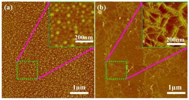
In aqueous environments, silk fibroin self-assembles slowly to form different nanostructures. As shown in Figure 1a, the nanospheres formed in fresh silk fibroin solution depends on chain folding and hydrophobic interactions.14 When the fresh silk fibroin solution was concentrated slowly, providing sufficient time for self-assembly, nanofilaments composed of the nanospheres appeared in the concentrated silk fibroin solution.15 The nanofilaments remained stable in aqueous solution. Even when diluted to 0.000001wt%, the silk fibroin maintained nanofibrous structures for several days (Figure 1b). The dynamic light scattering (DLS) results also confirmed the nanostructural changes in the silk fibroin solutions. As shown in Figure S1, fresh silk fibroin solution had a peak at about several ten nanometers, indicating the micelle formation while a broad peak at several hundred nanometers appeared in the concentrated solution, implying the aggregation from micelles to nanofibrils.
Figure 1.
AFM images of silk fibroin after different treatments: (a) fresh silk fibroin solution; (b) sample (a) slowly concentrated to 25 wt% at room temperature, the drying time was about 4 days. Before observation, all samples were diluted to 0.000001wt% to generate a single layer on the mica surface.
3.2 SF Electrospin Solutions
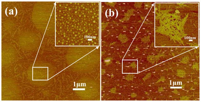
In order to transfer nanospheres from fresh solution and nanofilaments from slowly concentrated solution to formic acid solution, silk fibroin films were prepared by quickly drying and very slow drying of fresh silk fibroin solutions,11 respectively, and then dissolving the materials in formic acid. The two different silk fibroin formic acid (FA) solutions were termed S-SF (nanospheres) and F-SF (nanofilaments), respectively. The nanostructures of silk fibroin in formic acid were assessed by AFM. Few SF nano-filaments were observed in this solution, but many globules about 1~5 μm in diameter on average were observed in S-SF solution (Figure 2a), while nanofilaments about 200 nm in length and 15 nm in diameter on average were main nanostructures in silk fibroin in F-SF solution (Figure 2b) that were similar to nanofilaments in concentrated silk fibroin aqueous solution (150–400 nm in length and 10–20 nm in diameter, Figure 1), indicating good stability for the SF nanostructures in formic acid.
Figure 2.
AFM images of SF electrospinning solution with a concentration of 0.000001wt%. (a) SF nanosphere solution (termed S-SF) prepared by dissolving fast drying SF films in formic acid; (b) SF nanofilament solution (termed F-SF) prepared by dissolving slow drying films in formic acid.
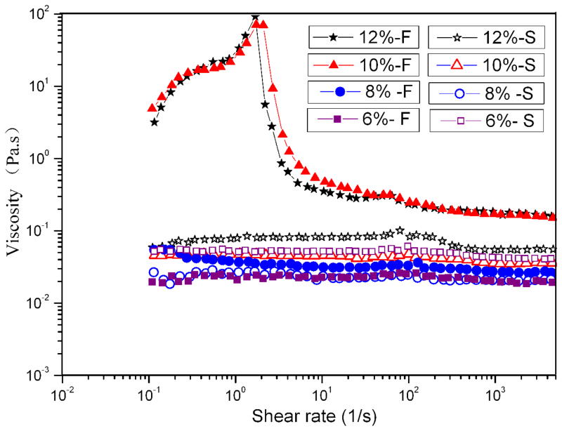
In order to study the SF inter-nanostructure associations present in electrospun FA solutions, viscometry was employed. Figure 3 shows the rheological behavior of SF electrospun solutions at 6%, 8%, 10%, and 12%. Viscosity measurements over a range of shear rates further emphasized the difference between the two solutions observed by AFM. Over the range of concentrations tested, S-SF solutions had only slightly different rheologies, and the viscosities were almost independent of shear rate, which suggested that for this solution there was a direct, positive link between amount of material and viscosity.13 As observed in AFM images, silk fibroin was present as globules, so the solution behaved as a Newtonian fluid with low viscosity, which was independent of shear rate and concentration.
Figure 3.
Viscosity shear rate profiles of SF electrospin solutions at four concentrations with different nanostructures: (S) nanospheres, (F) nanofilaments. SF nanosphere and nanofilament solution were prepared by dissolving fast and slow drying SF films in formic acid, respectively.
The F-SF solutions were very different in solution behavior. At low concentrations of 6% and 8%, the viscosity was independent of shear rate and the solutions were Newtonian, with low viscosity (Figure 3). However, at the higher concentrations of 10% and 12%, the F-SF solutions exhibited shear-thickening behavior followed by shear-thinning behavior with significantly higher viscosities, which is similar to natural silk dope.16 The repulsive forces between the negative charges in two nano-filaments was suppressed due to the low pH of FA,15, 17 so the nano-filaments organized in parallel or entangled,18 resulting in the increased viscosity and shear-thickening behavior at low shear rates, resulting in the increased viscosity and shear-thickening behavior at low shear rates. Shear thinning behavior was also observed at high shear rates (≥2s−1) likely due to orientation of the nanofilaments.
These data (AFM images and rheological behavior) indicated that, despite the same origin of SF molecules from native silk, the preparation process substantially altered the SF nano-structure which played an important role in the properties of the silk material generated.19, 20 The nanofilaments interactions resulted in significantly higher viscosity compared to the 6% and 8% F-SF solutions and all concentrations of S-SF solution in which no or few nanofilaments formed.
3.3 Electrospun SF Nanofibers
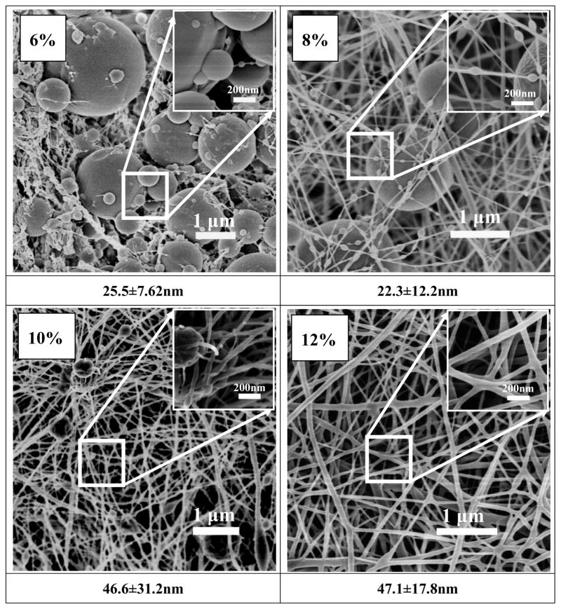
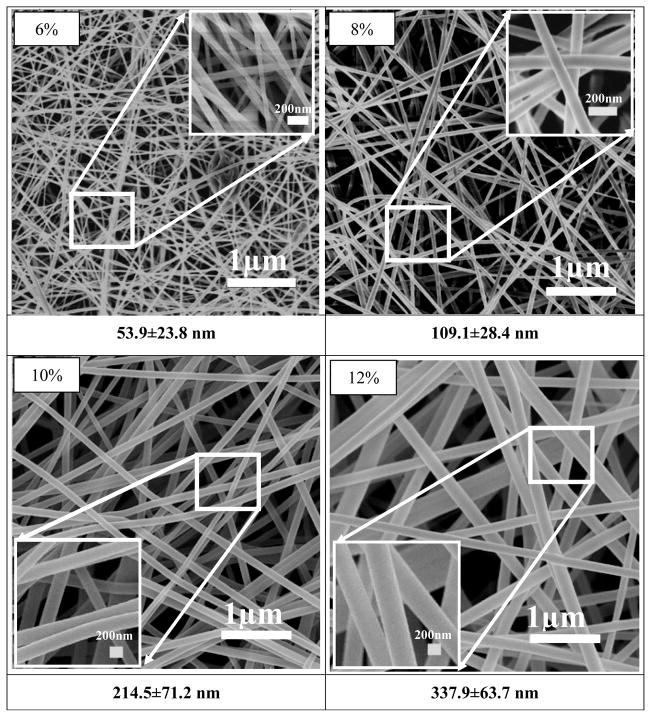
After silk fibroin solutions with nanostructures were prepared in FA solution, the spinnability and morphologies of electrospun silk fibers were investigated. Figures 4 and 5 show the morphology of electrospun fibers derived from S-SF and F-SF solutions, respectively. For S-SF solutions, the electrospun nonwoven mats were composed of spheres when the concentration was 6% (Figure 4a). The number of nanofibers with sizes several tens nanometers increased while the spheres decreased following an increase of silk concentration from 8% to 10% (Figure 4b, c). Finally, electrospun SF fibers with diameters of about 47 nm formed and the spheres were almost gone when the silk concentration was 12% (Figure 4d), in agreement with previous reports.8, 21
Figure 4.
SEM images of electrospun SF nonwoven mats derived from nanosphere solution. The formation of SF nanofibers required the high concentration (12 wt %). The diameters of nanofibers formed in electrospun SF nonwoven mats were listed below each SEM images.
Figure 5.
SEM images of electrospun SF nanofibers derived from nanofilament solution. The SF nanofibers formed at all concentrations.
Different spinnability and morphologies of electrospun fibers appeared when nanofilaments were self-assembled in the F-SF solution. At 6% concentration fibers with a diameter of about 50 nm formed with few beads, which was not achievable for the S-SF solutions. With the increase of silk fibroin concentration from 6% to 12%, the diameter of the electrospun nanofibers increased from 50 nm to 300 nm. At 6% or 8% solutions the F-SF achieved better spinnability despite lower viscosity. The results indicated that the nanostructure, especially the formation of nanofilaments in solution, was key for silk fibroin electrospinning. Moreover, following the increase of concentration, the nanofilaments in FA solution aggregated and entangled, resulting in an increase of viscosity (Figure 3) and increase in diameter of electrospun fibers (Figure 5). The results suggested that size control of silk electrospun fibers became feasible by changing the nanostructure of silk and the concentrations of the solution.
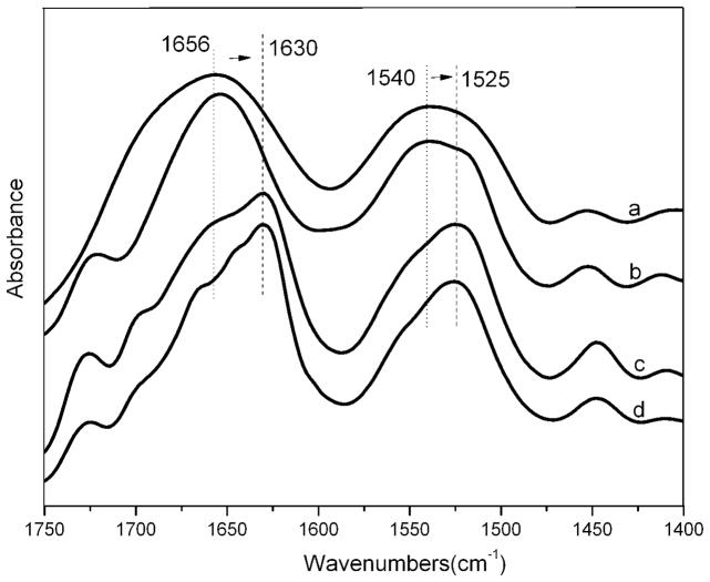
FTIR analysis was carried out to investigate structural changes of SF nanofilaments prepared from S-SF and F-SF solutions before and after 75% ethanol post-treatment (Figure 6).22 The as-electrospun SF nanofibers prepared from the two different solutions (pure a and b in Figure 6) showed two broad absorption peaks with a center around 1656 cm−1 (amide I) and 1540 cm−1 (amide II), corresponding to random coil and or silk I conformation.23–25 To improve stability in water, the SF nanofibers were treated with 75% ethanol to induce the conformational transition to silk II with the characteristic absorption peaks at 1630 cm−1 (amide I) and 1525 cm−1 (amide II).26 The structure of electrospun SF nanofibers prepared with S-SF and F-SF solutions was similar before and after 75% ethanol treatment regardless of the presence of the nanofilaments. The mechanical properties of the electrospun SF nanofibers derived from F-SF displayed a breaking stress of 7.9 MPa and strain of 26.3% (before post-treatment),27 and 17.7 MPa and 25.5% (after 75% ethanol treatment) which were significantly higher than in previous reports28–30, suggesting a possible way to improve the strength property of electrospun SF nanofibers by controlling the formation of SF nanostructures although further study was necessary to elucidate the mechanism.19, 20, 25
Figure 6.
FT-IR spectra of electrospun SF nanofibers derived from solution containing nanospheres (a and c) and nanofilaments (b and d); before (a and b) and after 75% ethanol treatment (c and d).
3.4 Mechanism of Electrospun SF Nanofibers Formation
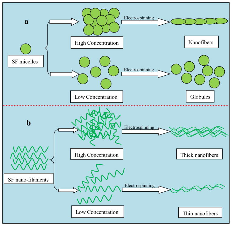
A mechanism is proposed to explain the SF nanofibers related to the electrospinning process (Figure 7). When S-SF solution was employed, mainly globules with weak interactions were present in solution, and since the concentration was low globules rather than fibers formed during electrospinning (Figure 4). With an increase in concentration, silk globules formed stronger interactions sufficient to prevent electrostatic forces during electrospinning, resulting in uniform nanofiber formation as in previous reports.14 Once nanofilaments self-assembled in silk solution (F-SF), the nanofilaments easily aligned in low concentration silk solutions under electrostatic forces to form electrospun nanofibers with diameters of about 50 nm. Following the concentration increase of silk fibroin nanofilaments in solution, the nanofilaments entangled even under electrostatic forces, leading to the formation of thicker electrospun fibers. The SF nanostructures also play an important role in mechanical properties of native and regenerated silk materials.18, 19, 24 Compared with electrospun silk fibers in previous studies,28–30 the electrospun fibers derived from F-SF solution achieved improved mechanical properties, implying the possibility of controlling mechanical properties of silk-based materials including but not limited to electrospun fibers through the control of silk fibroin nanostructures in solution. Aside from the elucidation that SF spinnability was significantly affected by SF nanoscale structures in solution, the present study also offer a new way to explore the preparation of regenerated silk-based materials with useful material properties.
Figure 7.
Model of electrospun SF nanofiber formation. (a) Globule formation driven by increased concentration of SF nanosphere solution, resulting in nanofiber formation after electrospinning nanosphere solution with high concentration (12 wt%). (b) SF nanofilaments in FA solution formed nanofibers under electrostatic force even with at concentration (6 wt%).
4. Conclusions
Silk nanostructure in solution, a key parameter for silk electrospinning, was studied. Nanofilament formation in silk solution increased the spinnability of silk and also improved the control of electrospun fiber diameter. Based on this new mechanism of control of silk solution for spinning, the design and preparation of silk electrospun scaffolds with controllable sizes and properties becomes feasible, which would further facilitate further utility in tissue engineering and drug release systems.
Supplementary Material
Acknowledgments
We thank the Priority Academic Program Development of Jiangsu Higher Education Institutions (PAPD) for support of this work. We also thank the National Natural Science Foundation of China (21174097) and the NIH for support of this work.
Footnotes
Supporting Information Available: Size distribution of silk fibroin after different treatments, size distribution of SF particles in formic acid, and the FTIR spectra results of regenerated silk films used to prepare electrospin solution. This material is available free of charge via the Internet at http://pubs.acs.org.
References
- 1.Omenetto FG, Kaplan DL. Science. 2010;329:528–531. doi: 10.1126/science.1188936. [DOI] [PMC free article] [PubMed] [Google Scholar]
- 2.Rockwood DN, Preda RC, Yucel T, Wang X, Lovett ML, Kaplan DL. Nat Protoc. 2011;6:1612–1631. doi: 10.1038/nprot.2011.379. [DOI] [PMC free article] [PubMed] [Google Scholar]
- 3.Gertz CC, Leach MK, Birrell LK, Martin DC, Feldman EL, Corey JM. Dev Neurobiol. 2010;70:589–603. doi: 10.1002/dneu.20792. [DOI] [PMC free article] [PubMed] [Google Scholar]
- 4.Tysseling-Mattiace VM, Sahni V, Niece KL, Birch D, Czeisler C, Fehlings MG, Stupp SI, Kessler JA. J Neurosci. 2008;28:3814–3823. doi: 10.1523/JNEUROSCI.0143-08.2008. [DOI] [PMC free article] [PubMed] [Google Scholar]
- 5.Xie J, MacEwan MR, Schwartz AG, Xia Y. Nanoscale. 2010;2:35–44. doi: 10.1039/b9nr00243j. [DOI] [PubMed] [Google Scholar]
- 6.Zhang X, Reagan MR, Kaplan DL. Adv Drug Deliv Rev. 2009;61:988–1006. doi: 10.1016/j.addr.2009.07.005. [DOI] [PMC free article] [PubMed] [Google Scholar]
- 7.Sill TJ, von Recum HA. Biomaterials. 2008;29:1989–2006. doi: 10.1016/j.biomaterials.2008.01.011. [DOI] [PubMed] [Google Scholar]
- 8.Sukigara S, Gandhi M, Ayutsede J, Micklus M, Ko F. Polymer. 2003;44:5721–5727. [Google Scholar]
- 9.Sukigara S, Gandhi M, Ayutsede J, Micklus M, Ko F. Polymer. 2004;45:3701–3708. [Google Scholar]
- 10.Jin HJ, Fridrikh SV, Rutledge GC, Kaplan DL. Biomacromolecules. 2002;3:1233–1239. doi: 10.1021/bm025581u. [DOI] [PubMed] [Google Scholar]
- 11.Lu Q, Hu X, Wang X, Kluge JA, Lu S, Kaplan DL. Acta Biomater. 2010;6:1380–1387. doi: 10.1016/j.actbio.2009.10.041. [DOI] [PMC free article] [PubMed] [Google Scholar]
- 12.Zhang F, Zuo B, Zhang H, Bai L. Polymer. 2009;50:279–285. [Google Scholar]
- 13.Holland C, Terry AE, Porter D, Vollrath F. Polymer. 2007;48:3388–3392. [Google Scholar]
- 14.Jin HJ, Kaplan DL. Nature. 2003;424:1057–1061. doi: 10.1038/nature01809. [DOI] [PubMed] [Google Scholar]
- 15.Lu Q, Huang Y, Li M, Zuo B, Lu S, Wang J, Zhu H, Kaplan DL. Acta Biomater. 2011;7:2394–2400. doi: 10.1016/j.actbio.2011.02.032. [DOI] [PMC free article] [PubMed] [Google Scholar]
- 16.Holland C, Terry AE, Porter D, Vollrath F. Nat Mater. 2006;5:870–874. doi: 10.1038/nmat1762. [DOI] [PubMed] [Google Scholar]
- 17.Zhu J, Zhang Y, Shao H, Hu X. Polymer. 2008;49:2880–2885. [Google Scholar]
- 18.Chen X, Knight DP, Vollrath F. Biomacromolecules. 2002;3:644–648. doi: 10.1021/bm0156126. [DOI] [PubMed] [Google Scholar]
- 19.Porter D, Vollrath F. Adv Mater. 2009;21:487–492. [Google Scholar]
- 20.Keten S, Xu Z, Ihle B, Buehler MJ. Nat Mater. 2010;9:359–367. doi: 10.1038/nmat2704. [DOI] [PubMed] [Google Scholar]
- 21.Min BM, Lee G, Kim SH, Nam YS, Lee TS, Park WH. Biomaterials. 2004;25:1289–1297. doi: 10.1016/j.biomaterials.2003.08.045. [DOI] [PubMed] [Google Scholar]
- 22.Hu X, Kaplan DL, Cebe P. Macromolecules. 2006;39:6161–6170. [Google Scholar]
- 23.Chen X, Shao Z, Marinkovic NS. Biophys Chem. 2001;89:25–34. doi: 10.1016/s0301-4622(00)00213-1. [DOI] [PubMed] [Google Scholar]
- 24.Zhou S, Peng H, Yu X, Zheng X, Cui W, Zhang Z, Li X, Wang J, Weng J, Jia W, Li F. J Phys Chem B. 2008;112:11209–11216. doi: 10.1021/jp800913k. [DOI] [PubMed] [Google Scholar]
- 25.Lu Q, Wang X, Lu S, Li M, Kaplan DL, Zhu H. Biomaterials. 2011;32:1059–1067. doi: 10.1016/j.biomaterials.2010.09.072. [DOI] [PMC free article] [PubMed] [Google Scholar]
- 26.Li C, Vepari C, Jin HJ, Kaplan DL. Biomaterials. 2006;27:3115–3124. doi: 10.1016/j.biomaterials.2006.01.022. [DOI] [PubMed] [Google Scholar]
- 27.Zhang F, Zhang H, Zuo B, Zhang X. Polym Sci Ser A. 2011;53:397–402. [Google Scholar]
- 28.Ayutsede J, Gandhi M, Sukigara S, Micklus M, Chen H, Ko F. Polymer. 2005;46:1625–1634. [Google Scholar]
- 29.Jin HJ, Chen J, Karageorgiou V, Altman GH, Kaplan DL. Biomaterials. 2004;25:1039–1047. doi: 10.1016/s0142-9612(03)00609-4. [DOI] [PubMed] [Google Scholar]
- 30.Chen C, Cao C, Ma X, Tang Y, Zhu H. Polymer. 2006;47:6322–6327. [Google Scholar]
Associated Data
This section collects any data citations, data availability statements, or supplementary materials included in this article.


