Abstract
Shape memory polymer (SMP) foam possesses structural and mechanical characteristics that make them very promising as an alternative treatment for intracranial aneurysms. Our SMP foams have low densities, with porosities as high as 98.8%; favorable for catheter delivery and aneurysm filling, but unfavorable for attenuating X-rays. This lack of contrast impedes the progression of this material becoming a viable medical device. This paper reports on increasing radioopacity by incorporating a high-Z element, tungsten particulate filler to attenuate X-rays, while conserving similar physical properties of the original non-opacified SMP foams. The minimal amount of tungsten for visibility was determined and subsequently incorporated into SMP foams, which were then fabricated into samples of increasing thicknesses. These samples were imaged through a pig’s skull to demonstrate radio-opacity in situ. Quantification of the increase in image contrast was performed via image processing methods and standard curves were made for varying concentrations of tungsten doped solid and foam SMP. 4% by volume loading of tungsten incorporated into our SMP foams has proven to be an effective method for improving radio-opacity of this material while maintaining the mechanical, physical and chemical properties of the original formulation.
Keywords: Radio-opacity, Aneurysm, Coils, Shape memory polymer, Fluoroscopy
INTRODUCTION
Cerebral aneurysms are localized dilations of an artery wall in the vasculature of the brain, are unstable in structure due to thinning of the arterial wall, and are thus prone to rupture.28 Aneurysm rupture into the subarachnoid space occurs in approximately 10 per 100,000 people in the United States annually,9,29 with the majority of people ending up dead or severely debilitated.9 Approximately 3–5% of the general population is thought to have cerebral aneurysms.9,42 Due to the high mortality and morbidity associated with rupture, early and effective treatment of an intracranial aneurysm prior to rupture can increase a person’s survival rate and quality of life.9
The two most common FDA-approved treatments treating cerebral vascular aneurysms involve isolation of the weakened portion of vessel via surgical clipping 31 and endovascular embolization through the use of flexible platinum coils. Surgical clipping involves a craniotomy, an invasive surgery of the brain, which carries serious inherent risks to the patient. Furthermore, surgical clipping is not always possible due to an inaccessible location of the aneurysm within the brain or the patient being a high risk candidate for surgery due to age or associated medical conditions. As a result of these limitations on surgical clipping, endovascular treatment has become an increasingly attractive option. The coils are introduced to the aneurysm endovascularly via a microcatheter. This filling treatment involves isolation of the weakened area of artery from the rest of the vasculature, ideally resulting in the regrowth of the endothelium, the innermost layer of the artery over the entry point or “neck” of the aneurysm. Further, this endovascular treatment is not perfect in avoiding aneurysm rupture and subsequent hemorrhage, but they have been shown to be superior to clipping in both ruptured and unruptured aneurysms. 5,21,24,31
While being the favored treatment for intracranial aneurysms, coils do have drawbacks, such as the possibility of coil compaction and subsequent formation of new side aneurysms adjacent to the original aneurysm, 20,48 low packing volume (less than 50% of the total aneurysm volume23,25,34) leading to recanalization or refilling,18 migration of loose coils into the parent artery,44 and although uncommon, potential puncture of the aneurysm dome during coil placement.11 Additionally, coils are not very successful at treating aneurysms with neck diameters greater than 4 mm.34 In these large neck aneurysms, approximately one-third of coil treated aneurysms either rebleed or recanalize.12,32,36,41 It has also been shown that endothelialization at the base of the aneurysm is limited due to low endothelial cell adhesion on the platinumsurface.26 Therefore, although coil treatment is the preferred filling method by interventionalists, there is still room for improvement in terms of the safety and efficacy of these devices.
The drawbacks of the commonly accepted treatments have spurred development of alternative aneurysm filling methods. Some of these technologies include treatment with multiple commercial devices,22 hydrogel polymer,18 collagen based coils,26 hybrid metal and hydrogel coils,1 shape memory polymer (SMP) coils19 and polymer foams.34,39,46,47 Previously, it has been proposed by Hampikian et al.,19 that radiopaque SMP coils be used to fill aneurysms. This paper focuses on SMP foams as an aneurysm filling method.10,34,40 In theory, the foam provides a scaffold for clotting in a large sub-volume of the aneurysm that may have advantages over coils.3,30 SMP foams are soft, compliant materials that have the ability to be fabricated into essentially any shape. This initial geometry can then be deformed by raising the temperature of the material above its transition temperature and applying a force. Continuing to apply force while cooling below its transition temperature programs the material into a secondary, temporary shape. The SMP foam would remain in its temporary shape until it is again heated above its transition temperature. For the purposes of aneurysm treatment, a foam of a given size and shape matching that of the aneurysm would be crimped onto a delivery device, directed into the aneurysm, and then deployed using either an external energy source or the body temperature of the patient.
These SMP foams are polyurethane based45 and have favorable biocompatibility.6 One drawback, however, is that these polymer foams have no inherent radio-opacity and are not visible using conventional patient imaging modalities (e.g., fluoroscopy). This limitation would reduce the likelihood of clinical use, as without the ability to visualize it, the material could not be delivered safely.4 The first aim of this research was to address this lack of radio-opacity, and develop SMP foams that exhibited radio-opaque characteristics using standard imaging and superimposition of bony and soft tissue structures, with the intention of advancing the clinical application of this technology.
To increase the radio-opacity of our SMP foam, tungsten was added to the polymer matrix prior to curing. To minimize the change in the material properties, it was essential to use the smallest amount of tungsten possible that still provided adequate opacity. Mechanical, chemical and physical properties before and after the addition of contrast agent were compared to determine the affects of adding this opacifying agent to the SMP foam. The properties tested include tensile strength, and glass transition temperature. In addition to mechanical, chemical and physical properties, biocompatibility was also evaluated with a pilot study of one animal consisting of two vein pouch aneurysms with an implantation time of 90 days.
MATERIALS AND METHODS
Neat Shape Memory Polymer Sample Preparation: Determination of Minimal Amount of Contrast Agent Necessary for Visibility
Solid, otherwise known as neat SMP material, was used to determine the minimum amount of contrast necessary to create a visible change in fluoroscopic imaging of the SMP material. Fine tungsten powder, <1 μm in diameter based on manufacturer specifications (Alfa Asear, Ward Hill, MA), was added in varying concentrations to neat SMP, and the materials were then cut into samples of increasing thicknesses. These samples were placed on top of a porcine head used to mimic the density of a human skull, and were imaged fluoroscopically to determine the minimum material thickness and the lowest concentration necessary for the polymer to be visible.
Solid Polymer Fabrication
Neat network polyurethane SMP samples were fabricated based on a variation of a composition specified by Wilson et al.45 in 2007, using stoichiometric ratios of polyol and diisocyanate monomers. Triethanolamine was added in a 2.0% excess (by mass). N,N,N′,N′-Tetrakis(2-hydroxypropyl)ethylenediamine (HPED, 98%) (TCI America©, Portland, OR), triethanolamine (TEA ≥ 99.5%) (Sigma-Aldrich Co.©, St. Louis, MO) and hexamethylene diisocyanate (HDI, 98%) (TCI America©, Portland, OR) were decanted in a precise basic controlled atmosphere glove box (LabConco Corporation©, Kansas City, Missouri) under a dry air atmosphere into glass jars and were subsequently sealed. The monomer-containing jars were then removed from the glove box and transferred to a vacuum oven, loosely opened for degassing, and degassed for 36 h at 45 °C at 1 Torr. At the end of the degassing cycle, the monomer containers were re-sealed and transferred back to the glove box. The appropriate masses for 0.5, 1.0, 2.0 and 4.0% by volume of tungsten powder (<1 μm particle size, 99.95% purity) (Alpha Aesar®, Ward Hill, MA) were measured out and placed into 60 mL maximum volume mixing containers (FlackTek™, Inc. Landrum, SC) which were then transferred to the glove box. The purge/fill cycle of the glove box was run for at least 5 cycles prior to transferring monomers into their respective containers.
The alcohol monomers, 0.4 mol of HPED and 0.19 mol of TEA, were added to the containers with the appropriate amount of tungsten, sealed tightly and then removed from the glove box. The 1.00 mol of HDI monomer, stored in a desiccator until use, was then added to the containers in the fume hood. After combining all of the monomers and tungsten, the containers were mixed for 2 min at 2400 rpm using the DAC 150 speed mixer (FlackTek™, Inc. Landrum, SC).
A volume of 3 mL of the mixture was transferred to 5 mL lurelock syringes. This volume was chosen such that the stoppers had ample room to move during degassing without separating from the syringe. The syringes, with a cap tightly secured on the tip, were put into a sonicator for 1.5 min. The exterior of the syringes were dried, the caps loosened, and then they were placed in a bell jar for 1.5 min under vacuum. The samples were removed from the bell jar, caps retightened, and the sonication step was repeated for 1.5 min. After sonication, the syringe caps were punctured with a needle and placed back into the bell jar for another 20 min under vacuum. The samples were initially held at room temperature for 2 h, and then the temperature was increased at a rate of 30 °C/h 120 °C was reached, at which point the temperature was held constant for 1 h prior to slow cooling to room temperature.
Solid Sample Preparation
Use of 5 mL syringes as casting molds resulted in 12.3 mm diameter cylinders of polymer doped with the varying amounts of tungsten (0.5, 1.0, 2.0 and 4.0%). These cylinders were then cut to thicknesses of 0.25, 0.5, 1.0, 1.5, 2.0, 2.5, 3.0, 3.5, 4.0, 4.5, 5.0, 6.0, 7.0, 8.0, 9.0 and 10.0 mm by an IsoMet 11-1280-160 saw (Buehler®, Lake Bluff, Illinois). One control of 0% tungsten SMP polymer was cut into a 10.0 mm sample.
Multiple Samples Mounted in one Holder: Preliminary Imaging
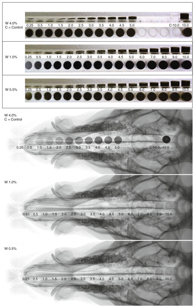
Samples of increasing thicknesses of 0.5, 1.0, 2.0 and 4.0% tungsten-doped SMP were mounted in and acrylic holder, one for each concentration, etched by a LS100 laser cutter (Gravograph®, Duluth, GA) to allow for ease of imaging in one frame (Fig. 1).
FIGURE 1.
Increasing thicknesses of 0.5, 1.0, and 4.0% tungsten doped neat polymer samples mounted in an acrylic holder, samples imaged via fluoroscopy at TIPS.
Samples Mounted Separately: Quantitative Imaging
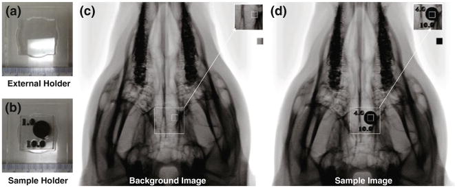
Neat samples of all concentrations and increasing thicknesses were individually mounted into acrylic holders that were laser etched by a LS100 laser cutter. Each acrylic sample holder was identified by radioopaque markers that indicated concentration and sample height (Fig. 2b).
FIGURE 2.
Controlled sample positioning imaging setup. (a) External holder to secure the sample to the pig’s head in the same position in all images, (b) sample holder mounted inside of the external holder, top number is the concentration of tungsten, and the bottom number is the thickness in mm, (c) background image consisting of the pig’s skull and the external holder, (d) sample image consisting of the pig’s skull, external holder and sample.
Determination of Minimal Polymer Loading by Fluoroscopic Imaging
The neat polymer samples with a pig (Fig. 1) were imaged at the Texas Institute for Preclinical Studies (TIPS) at Texas A&MUniversity, using an AlluraXper FD20 (Philips® Healthcare, Andover, MA) fixed fluoroscope. Single image plane images were acquired at a rate of 3 frames per second, with an exposure of 22 mAs, using Allura Xper 7.2.1 software, with the voltage potential set to 70 kV. The source to detector, and source to sample distances were set to 1195 and 810 mm respectively for all samples. All samples were imaged using these power settings for the remaining imaging sessions of this paper. Each of the samples, mounted in their respective holder, was imaged to show the relative increase in contrast observed for each set of samples for each concentration.
Qualitative Radio-Opacity of SMP Foam
Foam Preparation
Polyurethane SMP foam samples were prepared with the same monomers as the neat polymer samples, using HDI, HPED and TEA. These monomers were premixed forming an isocyanate prepolymer and stored in a desiccator for 42 h prior to being mixed with the alcohol premix, catalysts and surfactants. The isocyanate prepolymers were foamed by adding alcohol premix (TEA), catalysts and surfactants (DC-5179, DC-I990, T131, BL-22 (Air Products and Chemicals, Inc. ®, Allentown, PA)) and blowing agents (DI water and Enovate (Honeywell International Inc. ®, Morristown, NJ)), and then mixed by a DAC 150 speed mixer for 15 s at 3400 rpm. An overall NCO/OH ratio of 1.05 was used for foaming. The foams were cured at 90 °C under vacuum for 12 h.
Both the SMP foam and tungsten-doped SMP foam were made in a similar manner. The 4% by volume tungsten foam was made by adding 28.978 g of tungsten to the isocyanate premix and mixed for 30 s in the DAC 150 speed mixer mixer at 3400 rpm. The alcohol premix was then added, and mixed for another 15 s at 3400 rpm. A volume of 3 mL of blowing agent (Enovate) was added to the mixture, and was allowed to vent while mixed for another 15 s at 3400 rpm. While the foam began to raise it was then allowed to sit at room temperature for 5 min prior to being placed in a 90 °C preheated oven. To support the cell structure as it cured, a vacuum was gradually pulled. After 1 h, the temperature was allowed to gradually decrease to room temperature; however, the vacuum remained on while the foam cured overnight.
Foam Sample Preparation
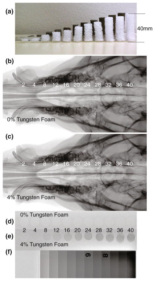
Cylinders of foam, 12 mm in diameter, were cut using biopsy punches. Samples of 0 and 4% tungsten-doped foams were cut to be eight times the sample height of the neat polymer samples, which resulted in cylinders with heights of 2, 4, 8, 12, 16, 20, 24, 28, 32, 36, and 40 mm (Fig. 3a).
FIGURE 3.
(a) Profile view of 0 and 4% tungsten-doped SMP foam samples, (b) Control 0% tungsten-doped SMP foam device with increasing thicknesses from 2 to 40 mm imaged via fluoroscopy with a pig’s skull thickness, (c) 4% tungsten-doped SMP foam device with increasing thicknesses from 2 to 40 mm imaged via fluoroscopy with a pig’s skull thickness, (d) Control 0% tungsten-doped SMP foam device with increasing thicknesses from 2 to 40 mm imaged via fluoroscopy, (e) 4% tungsten-doped SMP foam device with increasing thicknesses from 2 to 40 mm imaged via fluoroscopy, (f) Aluminum standard.
Multiple Foam Samples Mounted in One Holder: Preliminary Imaging
Foam cylinders of increasing heights, made of both the 0 and 4% tungsten foams, were mounted in acrylic holders similar to the solid samples (Fig. 3a), that were laser etched by a LS100 laser cutter.
Foam Samples Mounted Separately: Quantitative Imaging
Samples of the same concentration and heights used in the preliminary imaging step were also individually mounted into acrylic holders that were laser etched by a LS100 laser cutter and individually identified by radio-opaque tags that indicated concentration and sample height (Fig. 2b).
Qualitative Determination of Radio-Opacity of SMP Foams via Fluoroscopic Imaging
The samples of 0 and 4% tungsten foams that were mounted in their respective acrylic holder were imaged using via fluoroscope, using the same settings as before, both with a pig’s skull thickness (Figs. 3b, 3c) and alone next to a radiographic standard (Figs. 3d–3f).
Radio-Opacity of Crimped SMP Foams
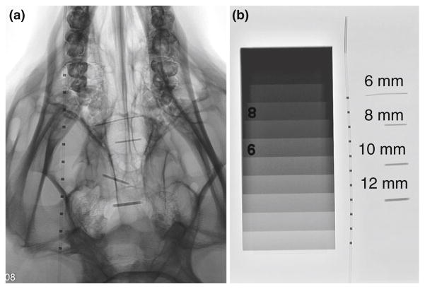
Multiple diameters of biopsy punches, 6, 8, 10 and 12 mm, were used to make cylindrical tungsten-doped samples of foam. These samples were crimped radially, parallel to the central axis, to their minimum diameter with a ST150-42 stent crimper (Machine Solutions Inc. ®, Flagstaff, Arizona), at 100 °C, and allowed to cool to room temperature for 2 h. Crimped samples were imaged through the crimped cylinder thickness using a fluoroscope, with a pig’s skull and tissue, next to a microcatheter to observe their relative radio-opacity (Figs. 4a–4b).
FIGURE 4.
(a) Mechanically crimped 4% tungsten-doped SMP foam imaged via fluoroscopy, original diameters: 6, 8, 10 and 12 mm with a pig’s skull thickness next to a catheter with radio-opaque platinum bands, (b) mechanically crimped 4% tungsten-doped SMP foam imaged via fluoroscopy, original diameters: 6, 8, 10 and 12 mm next to the same catheter as in 4A.
Quantification of Image Contrast of Solid SMP and Foams
A stationary external acrylic mount was laser etched by a LS100 laser cutter to ensure proper positioning of the individually mounted samples while being imaged (Fig. 2a). The individually mounted samples of solid SMP and foam were imaged using a fluoroscope by securing the external holder to the pig’s head, and imaging each sample down the center of its cylindrical geometry, as seen in Fig. 2d, to quantify the increase in image contrast as material thickness increased. Additionally, images with the external holder secured to the head without a sample were obtained as the background images; the background image representing the contrast obtained from a pig’s head (Fig. 2c).
The original fluoroscopic images acquired were converted from Digital Imaging and Communications in Medicine (DICOM) to 8 bit Tagged Image File Format (TIFF) format and imported into Matlab® R2008a (MathWorks®, Natick, MA), where they were processed using the Image Processing Toolbox. Each image, originally 512 × 512 pixels in dimension, with a resolution of 0.439 mm/pixel, including an averaged background image, were cropped to a 15 × 15 pixel, equivalent to 6.6 mm × 6.6 mm image (Figs. 2c– 2d)—a region well within the area (120 mm2 for neat samples and 110 mm2 for foam samples) of the sample portion within the image. Using the cropped images, the sample images were subtracted from the background image. The difference in contrast was determined for each pixel from the 15 × 15 pixel images.
Differential Scanning Calorimetry
Differential Scanning Calorimetry was performed on all samples using a Q200 (TA Instruments®, New Castle, DE), using a heat-cool-heat cycle (an initial ramp of 20 °C/min up to 150 °C, held isothermal for 2 min, then ramped down to −40 °C at a rate of 20 °C/min, held isothermal for 2 min, and then ramped back up to 150 °C at a rate of 20 °C/min) detailed by Wilson et al.45 Six samples were run at each concentration for all neat SMP and foam concentrations.
Mechanical Testing
Stress/strain behavior of the 0 and 4% by volume tungsten-doped foams were determined via strain to failure experiments using an Insight 30 material tester (Materials Testing Solutions MTS® Systems Corporation, Eden Prairie, MN). Due to fabrication methods of our foams, sample size was limited to 60 mm × 15 mm × 6 mm. Following the ASTM D638-Standard Test Method for Tensile Properties, ten samples of each concentration were tested utilizing a speed for non-rigid samples at a constant strain rate of 50 mm/min at room temperature.2
Scanning Electron Microscopy
Foam samples were dried in an oven preheated to 90 °C for12 h under vacuum. SEM analysis was carried out on foam blocks of 5 mm × 5 mm × 5 mm in dimension. The foam samples were secured to the holder using double-sided carbon tape that were then sputter-coated with gold and palladium to increase the conductivity and to prevent charge build-up of the electrons absorbed by the specimen. The morphology of the foam samples were analyzed using a Quanta 600 field emission scanning electron microscope (FEI®, Hillsboro, Oregon).
Porcine Implants of 4% Tungsten-Doped Foams
4% tungsten-doped SMP block of foam was machined into two 12 mm spherical samples using a MDX-540 Roland 3D Mill (Roland© DGA Corporation, Irvine, California). These samples were cleaned and sterilized via ethylene oxide to prepare them for implantation. A porcine animal model previously reported by Guglielmi in 1994,17 was utilized to simulate in vivo aneurysm conditions for histological evaluation and healing of 4% tungsten-doped SMP foam. This model is constructed by the use of a harvested vein segment, in which one end of the segment is sewn onto an opening created on the carotid artery, with the opposite end tied off at the apex to create a pouch.17 These samples were implanted into the aneurysms located on both the left and right carotids. The implanted materials remained 90 days within the aneurysms prior to sacrifice.
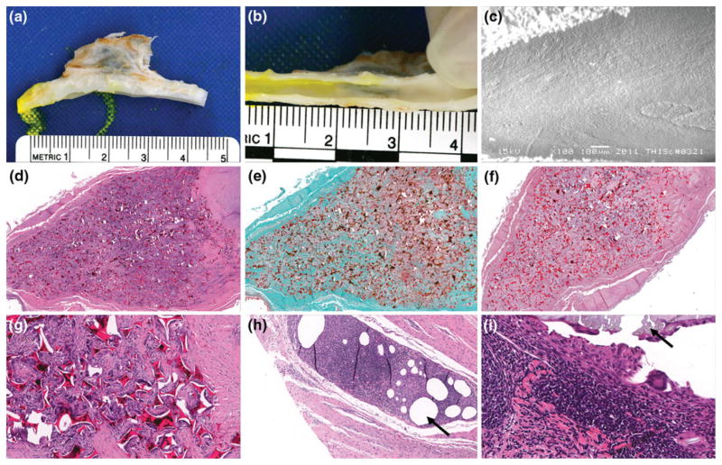
Vessels were harvested, fixed via formalin, and both pathology and SEM were performed to analyze healing. Histology of the vessels included embedding of tissues in paraffin, and serial sectioning of the aneurysm domes. For microatomic histological evaluation, or presence of cells associated with inflammation, hematoxylin and eosin (H&E) was used to stain the tissues; this staining elucidates the nuclear structures by staining them blue, and all other eosinophilic structures pink or orange. Masson’s trichrome and Phosphotungstic acid haematoxylin (PTAH) was used to evaluate connective tissues, such as fibrin and collagen. Trichrome dyes erythrocytes orange, cell cytoplasm red and collagen fibers blue. PTAH stains collagen fibers reddish-pink and fibrin fibers blue. Three serial sections of the aneurysms were evaluated: proximal to the aneurysm orifice, middle aneurysm dome and apex of the dome. Overall healing for all areas was reported; magnifications evaluated were 3.5, 4, 10 and 20×. The initial gross results demonstrated in Fig. 10b, and the morphology of the lesion were verified and evaluated by SEM imaging of the same area (Fig. 10c).
FIGURE 10.
SEM and pathology results of implanted foams: (a) Gross picture of dissected aneurysm and parent vessel, (b) Gross picture of healing that took place between aneurysm and parent artery intersection (en face), (c) SEM of endothelial cell morphology across the ostium (100× magnification), (d) H&E cross-section of bisected artery and aneurysm sac (4× magnification), (e) trichrome cross-section of bisected aneurysm sac (4× magnification), (f) PTAH cross-section of bisected artery and aneurysm sac (3.5× magnification), (g) H&E Cross-section of bisected artery and aneurysm sac (20× magnification), (h) H&E detail of the FDA approved suture material, polypropylene, indicated by the black arrow (10× magnification), and (i) H&E detail of the FDA approved suture material, silk, indicated by the black arrow (40× magnification).
This work was approved by and performed in accordance with guidelines of the Texas Institute for Preclinical Studies, and Texas A&M University’s (Institutional Animal Use and Care Committee, IACUC), and that it adheres to the Guide in the Care and Use of Laboratory Animals established by the US National Academy of Sciences (or guidelines that insure equivalent or higher standards of care).
RESULTS
Determination of Minimal Tungsten Loading of Polymer via Fluoroscopy Imaging
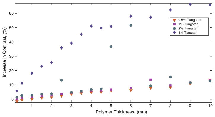
Thicknesses of solid SMP samples mounted in acrylic holders were imaged fluoroscopically superimposed on a pig head to determine minimal percentage of tungsten loading that could be seen in thin samples (~1 mm). Neat polymer samples cut from all concentrations (0.5, 1.0, 2.0 and 4.0%) tungsten were imaged, as seen in Fig. 1. This set of images indicated 4% tungsten samples were able to produce clearly defined regions of contrast, and poorly defined regions of increased contrast were observed by samples made from the lower concentrations. It was determined that 4% tungsten by volume loading would be sufficient for the doped foam samples for the remainder of the experiment.
Qualitative Determination of Radio-Opacity of SMP Foams via Fluoroscopic Imaging
Expanded Foams
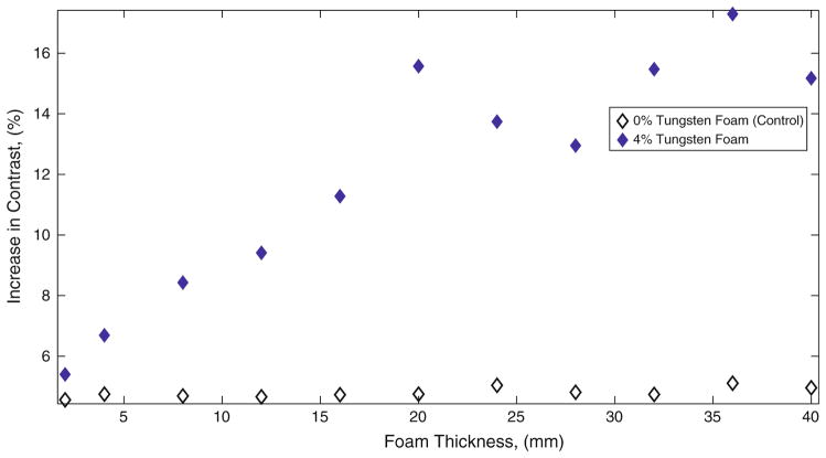
All of the 0% tungsten foams (Figs. 3b, 3d) were not visible when imaged via fluoroscopy, both superimposed with a pig’s skull and alone, next to the radiographic standard. The 4% tungsten-doped aneurysm foams imaged (Figs. 3c, 3e) were visible at thicknesses greater than 8 mm when superimposed with a pig’s skull. When imaged without being superimposed with a pig’s skull, the 4% tungsten foams of all thicknesses greater than 2 mm were visible when imaged next to the radiographic standard. The image contrast obtained by 40 mm of 4% tungsten-doped foam was measured to be equivalent to 1 cm thickness of aluminum (Figs. 3e, 3f).
Crimped Foams
Crimped 4% tungsten-doped SMP foams (6, 8, 10 and 12 mm original diameter) were made and imaged via fluoroscopy with a pig and next to a catheter and a radiographic standard (Figs. 4a–4b). When imaged without the pig’s skull thickness, the crimped samples (6, 8, 10 and 12 mm original diameter) exhibit contrast levels similar to aluminum between 2 and 4 cm thicknesses respectively, when compared to the radiographic standard (Fig. 4b). The crimped foams were superimposed on the pig skull (Fig. 4a), demonstrating visibility for devices with an original thickness of at least 6 mm and increasing visibility with increasing original diameter, or material thickness.
Quantification of Image Contrast of Solid SMP and Foams
Samples from 0.5, 1.0, 2.0 and 4.0% tungsten-doped neat polymer, 0 and 4% tungsten-doped SMP foam were imaged using fluoroscopy in the same position, positioned by the external stationary holder (Fig. 2a) secured to the top of a pig’s skull as seen in Fig. 2d. Raw data was acquired in DICOM format, converted to TIFF format where each individual sample image was subtracted from a background image, and data was plotted as difference in contrast vs. polymer thickness, as seen in Fig. 5 for solid polymer samples, Fig. 6 for foam samples. Figure 5 quantifies the increased contrast obtained from the solid polymer samples superimposed on the pig’s head. The observed increase in contrast obtained from all thicknesses of control SMP foams as seen in Fig. 3b is not visible to the human eye. As seen in Fig. 3c, foams greater than 8 mm show up on fluoroscopic images; indicating that increase in contrast obtained by these samples are visible to the eye. Figure 6 compares the percentage of increase in image contrast vs. sample thickness for 0 and 4% tungsten-doped foams.
FIGURE 5.
Percentage of increase in contrast obtained by neat polymer samples.
FIGURE 6.
Percentage of increase in contrast obtained by SMP foam samples.
Differential Scanning Calorimetry
The differential scanning calorimetry data for all materials observed in this study is summarized in Fig. 8, where inflection point data for six samples per concentration is reported. The 0 and 4% tungsten foam samples had average glass transition temperatures of 83.4 and 83.4 °C, high glass transition temperatures of 85.3 and 85.7 °C and low glass transition temperatures of 81.1 and 82.2 °C, respectively. Solid polymer samples exhibited an average glass transition of 62.5 °C, and an overall range of glass transitions within 11.5 °C for all samples measured (Fig. 8).
FIGURE 8.
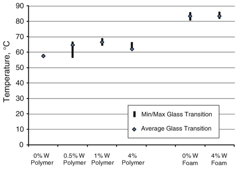
Glass transition data for solid SMP and SMP foam, n = 6 per concentration.
Mechanical Testing
A summary of the mechanical results were tabulated in Table 1. Breaking tensile strength increased in the 4% tungsten-doped foams when compared to the 0% tungsten foams. Breaking strain increased in the 4% doped tungsten foams when compared to the control (0% tungsten foams). On average, the doped foams exhibited an increase in Young’s moduli; the 4% tungsten-doped foams exhibited a Young’s modulus of 1670 ± 548, and the 0% tungsten, or control foams, exhibited a Young’s modulus of 1170 ± 406. Figure 7 is a representative stress strain curve for 0 and 4% tungsten-doped foams. The elastic behavior of these materials is represented by the linear region exhibited at strains less than 5%. There was an average increase in the modulus by 43% of the 4% tungsten-doped foams compared to the control foams.
TABLE 1.
Summary of mechanical property results.
| Breaking tensile strength (kPa) | Breaking strain (%) | Young’s modulus (kPa) | |
|---|---|---|---|
| Control SMP Foam | 78 ± 30 | 10 ± 3 | 1170 ± 406 |
| 4% Tungsten foam | 130 ± 25 | 16 ± 4 | 1670 ± 548 |
± One standard deviation, n = 10 per concentration.
FIGURE 7.
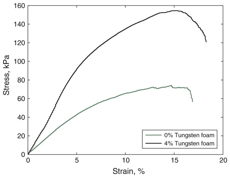
Representative stress strain curve of tensile testing of 0 and 4% tungsten foams.
Scanning Electron Microscopy
Figures 8a–8c are Scanning Electron Microscopy (SEM) images of 0 and 4% SMP foams. Figure 9a is a 40× magnification SEM image of the control (0% tungsten) SMP foam showing pore cell diameters roughly around 600 μm. In Fig. 9b, 4% tungsten-doped foam is shown at 40× magnification, and in this image, pore cells are shown to be heterogeneous, roughly ranging from 250 to 800 μm in diameter. Figure 9c is a 250× magnification SEM image of a 4% tungsten-doped foam sample, which exhibited the <1 μm diameter tungsten particles dispersed within the polymer matrix.
FIGURE 9.
(a) SEM micrograph of control SMP foam (40× magnification), (b) SEM micrograph of 4% tungsten SMP foam (40× magnification), and (c) SEM micrograph of 4% tungsten SMP foam (250× magnification).
Porcine Implants of 4% Tungsten-Doped Foams
SEM of Lumen of Artery at Foam Artery Interface
Figure 10 summarizes the SEM and pathological results from implanting 4% tungsten foams within a vein pouch porcine aneurysm model for 90 days. Figures 10a, 10b and 10c are representative of the healing response at the gross and microscopic scales. The left carotid aneurysm model failed due to vasospasm during implantation, which caused the artery to collapse on itself, and thereby eliminating patency of the parent artery. Due to a lack of blood flow interaction with the parent vessel, SEM imaging was not performed on the left carotid aneurysm. The right carotid remained patent throughout the 90 days of implantation, and the aneurysm/artery interface was imaged via SEM at 100× magnification at 15 kV. SEM imaging of the right carotid showed that there was complete covering of the exposed foam with endothelial cells aligned parallel to the arterial blood flow, the surface exhibited a lack of mural thrombi, and complete healing of the aneurysm lesion was observed. Macroscopically there is an evident presence of endothelial cells at the aneurysm and artery interface after 90 days (Fig. 10b). Additionally in Fig. 10c, the endothelial cells were mature and aligned to blood flow.
Pathology
Both carotid aneurysms were evaluated via histology. The left and right aneurysms were both composed of 75% connective tissue, and had minimal lumen narrowing (<5%) with respect to the neointima proliferation. More than 95% of the inner core of the aneurysms had been infiltrated by dense cellular connective tissue with regards to the healing that took place at the anastomosis interface, central core, and outer distal edge of the aneurysm dome. Inflammation of the central core and outer edge was minimal for both of the aneurysms; having less than 5% of the regions infiltrated by inflammatory cells.
Figure 10d is a hematoxylin and eosin stain (H&E) cross-section of bisected artery and aneurysm sac (4× magnification). The presence of blue stained nuclei helped determine the amount of multinucleated giant cells; an abundance of such cells indicates inflammation. However, as is shown in Fig. 10d, there are minimal amounts of multinucleated giant cells surrounding polymer struts, indicating a contained healing response within the dome of the aneurysm. For both aneurysms, less than 5% of the volume was filled with fibrin, and there was greater than 90% of collagen throughout the aneurysm (Fig. 10e). Additionally, in Fig. 10e, is a Trichrome cross-section of bisected aneurysm sac (4× magnification). It is shown in Fig. 10e that significant healing has occurred within 90 days, represented by blue stained collagen throughout the dome of the aneurysm, and minimal presence of red blood cell residuals. Figure 10f is a Phosphotungstic acid–hematoxylin (PTAH) cross-section of bisected artery and aneurysm sac (3.5× magnification). It is shown in Fig. 10f that there is more than 90% deposition of collagen, and less than 5% residual fibrin throughout the dome of the aneurysm. Figures 10h and 10i are histological details of the amount of inflammation present around suture materials, polypropylene and silk respectively. There were multifocal areas of mild chronic inflammatory cells proximal to the areas of suture material (Figs. 10h, 10i). These areas show a granulomatous inflammatory cell response to the suture materials represented by densely packed cells indicated by purple stained nuclei (Figs. 10h, 10i). When comparing the 4% tungsten-doped foam (Fig. 10g) to the silk and polypropylene suture materials, there is significantly less inflammation around the implanted polymer material (Figs. 10h, 10i).
DISCUSSION
The goal of this research was to determine the minimal amount of tungsten necessary to make SMP foam visible when imaged via standard clinical imaging methods. Creating cylindrical neat polymer samples doped with increasing concentrations (0.5, 1, 2 and 4% by volume) cut into samples of increasing thicknesses facilitated the plotting of a standard curve for each concentration to be made. Visibility of the 4% tungsten neat samples at 1 mm thickness demonstrated the feasibility of achieving clinically practical radio-opacity in the 4% tungsten-doped foams. This assumption was based on an expected 80× expansion ratio of neat polymer to foam, and the subsequent conclusion that approximately 1 mm thickness of tungsten doped neat polymer and 8 mm thickness of 4% tungsten-doped SMP foam contained relatively the same amount of tungsten. In previous research performed by Hampikian et al.19, 3% by volume doping of tantalum in SMP was successful at qualitatively creating visible X-ray contrast via fluoroscopy imaging at material thicknesses of down to 0.088 mm through water, which is consistent of our results. However, they did not perform imaging through bone and soft tissues, nor did they quantify the amount of contrast they achieved with 3% doping of their SMP.19
In order to quantify the degree of contrast at different concentrations of tungsten for both neat and foam SMP samples, the difference in pixel intensity from the background image was calculated for each of the samples. It was observed that when a sample of sufficient thickness increased image contrast, or darkened the image, by approximately 8% (Weber contrast) for an 8-Bit image, they were visible through the skull and associated soft tissues. The 0% tungsten (control) SMP foam of all heights was determined to increase the contrast by approximately 5% (Weber contrast43) over background in both the images taken with the skull thickness and when imaged alone, remained unidentifiable by visual inspection. By doping the SMP foam with 4% by volume of tungsten powder, it was determined that foam was visible at a thickness greater than 8 mm when superimposed with the skull and tissues, which was the case when there was an increase in the contrast by more than 8% by the sample (Weber contrast43).
Our proposed SMP aneurysm filling device consists of foam that would be crimped to its minimum diameter for delivery, and remain in this temporary state until it had been navigated into an aneurysm, at which point it would be actuated by heat to fill the sac. It was demonstrated that visibility of a crimped 4% tungsten-doped foam, original diameter of 6 mm (Fig. 4) was accomplished, and the increase in contrast observed by all of the crimped samples were approximately equal to 2–4 cm of aluminum when compared to the radio-opaque standard (Fig. 4b). The crimped samples exhibited a 25, 30, 33 and 37% increase in contrast for 6, 8, 10 and 12 mm original diameter samples respectively (Figs. 4a, 4b). Creating contrast by crimped foams of these diameters was a significant step toward clinical application, as the average size of berry aneurysms is approximately 8 mm in diameter, and the imaging used in this study was the same as would be employed in a clinical setting. Although the 4% tungsten doped 6 mm SMP foam was visible in the crimped state, the sample may not be visible when expanded in vivo. Clinically, this may not be an issue due to the similarities to the current clinical situation during endovascular treatment of aneurysms, in which the unsatisfactory or satisfactory nature of the embolization is defined by the presence or absence of filling of the aneurysm by blood (injected contrast dye), rather than by the appearance of the coils themselves.
An additional goal of this research was to determine if the addition of tungsten powder to the matrix of the polymer would greatly alter the transition temperature of our foams. For all the 24 neat polymer samples the average glass transition was 62.5 ± 3.9 °C (Avg ± Std. Dev.). Among the 12 foam samples measured the average was 83.6 °C, and the standard deviation was 1.3 °C. The addition of particulate tungsten powder at a concentration of 4% by volume did not significantly alter the glass transition of the foam material, and therefore, acted as an inert filler material. These results coincide with the previously published study by Cui et al.8, in which they demonstrated that the addition of particulate BaSO4 up to 40% by weight into polyurethane based SMP did not greatly affect the polymer matrix. Differential scanning calorimetry data showed that there was more variation of the glass transition temperatures among the neat polymer samples however; all samples in all concentrations and polymer forms were within approximately 10 °C of each other, indicating that the tungsten filler had little effect on the polymer matrix during fabrication.
The mechanical properties of the ten samples tested of each 0% (control) and 4% tungsten-doped SMP foams are summarized in Table 1. The addition of 4% tungsten to the SMP foam increased its breaking tensile strength, breaking strain, and Young’s modulus by 67, 60, and 43%, respectively. Previously, it has been shown by Gibson and Goods that there is a relationship between increases in cell density and an increase in the modulus of foam material,15,16 which may have been the case with the 4% tungsten-doped foams in our study. It was observed that the 4% tungsten-doped foams exhibited greater cell density than the 0% tungsten non-doped foams. Additionally, in 2002 and 2004, Gall et al.13,14 have demonstrated that the addition of a filler into SMP can increase modulus, and strength. More specifically related to foam materials, Saha,38 reported that the addition of nanoparticle filler materials to polyurethane foams increased the tensile strength and the modulus. Our material, also being based off of polyurethane chemistry, may be exhibiting similar mechanical behaviors.
Figures 9b and 9c are SEM images of the two concentrations of SMP foams tested. These figures are examples of the cell structures in both concentrations. From the SEM images, it is evident that the cell size and cell density of 0 and 4% tungsten-doped SMP foams are different. The 4% tungsten foam sample exhibited a higher cell density and appeared to be more heterogeneous in pore cell size, including smaller pore cell sizes than that of 0% tungsten SMP foams, which suggests that the <1 μm dispersed tungsten particles act as heterogeneous nucleation sites during cell formation. 7,33,38 Figure 9c shows the tungsten particles dispersed into the matrix of the polymer. These particles are potentially acting as points of stabilization throughout the material, thereby increasing the toughness of the foam, which is also exhibited by the mechanical testing (Fig. 7). Heterogeneity was seen in the tungsten-doped foams by the increased range in pore cell sizes exhibited in the SEM images.
Pathological results show that there was minimal inflammation (<5% fibrin deposition and less than 5% inflammatory cell infiltration) within the aneurysm dome. These results are all indicative that the tungsten-doped SMP is a biocompatible filling material for the treatment of aneurysms.
Relative to the addition of tungsten to the SMP, the risk of tungsten toxicity for tungsten coils has been addressed. Peuster et al.35 showed that slow degradation of tungsten coils emit small amounts (29 μg/day) of tungsten in the vasculature and is not toxic in vitro which has been validated clinically by the lack of toxicity to tungsten coils in patients. Note that we use much less tungsten in our foams (0.2 g for typical 8 mm foam sphere) than the average coils used by Kampmann et al.27 and Saatci et al.37 (12 g per coil, for a 0.25 mm DIA and 12.5 mm length of mechanically detachable spiral tungsten coils (MDSs)) and an average of 5 coils inserted per aneurysm. In Fig. 10g, a 20× magnification detail of the aneurysm dome, it is shown that the tungsten particulate is encapsulated within SMP, preventing it from leaching out at a fast rate in vivo. If leaching is present, it should be at such a slow rate that it would not be toxic to the patient, given that the material has remained intact for a time frame of 90 days in vivo. This previous research performed by Peuster et al.35 and this research support tungsten-doped polyurethane based SMP foams as a viable alternative filling material for treating intracranial aneurysms.
This research sought to accomplish multiple goals in the process of the development of a SMP foam aneurysm filling device. The first requirement addressed was the opacification of the SMP foam which would allow for visualization during endovascular treatments using standard imaging (fluoroscopy) while being superimposed with bony and soft tissue structures (imaging through a pig head), and we have demonstrated this. The second requirement addressed was that the mechanical properties of the opacified foam be similar, or better when compared to the original formulation of SMP foam. This second requirement was met when the foam was doped with 4% by volume tungsten particulate. The tungsten-doped foam not only maintained its integrity, but also exhibited an increase in its modulus based on the results of the stress to failure mechanical testing. The third requirement addressed related to the chemical properties of the material, which required that the addition of tungsten particulate not significantly change the transition temperature, for this material the glass transition temperature. The tight grouping of glass transition temperatures exhibited by the 0% (control) and 4% tungsten foams supports the success of this goal. The fourth requirement was that the 4% tungsten-doped SMP materials should not have a significantly higher inflammatory response in vivo when compared to FDA approved materials. This fourth requirement was met by the almost complete healing of the aneurysm site after 90 days, and the lack of inflammation when compared to the suture material. These results provide a significant advancement for these materials to be developed into aneurysms filling devices for clinical use. Further study is warranted; including more thorough biocompatibility tests of the 4% tungsten-doped SMP material in vivo and eventually clinical trials. This research serves as a foundation to support these future endeavors.
Acknowledgments
This work was supported by the National Institutes of Health/National Institute of Biomedical Imaging and Bioengineering Grant R01EB000462. We would like to thank Amanda Connor, Josh Bergerson, Casey McCurrin, Stephen Darrouzet, Brent Volk and Keith Hearon for their technical support on this research.
References
- 1.Arthur AS, Wilson SA, Dixit S, Barr JD. Hydrogel-coated coils for the treatment of cerebral aneurysms: preliminary results. Neurosurg Focus. 2005;18:1–9. doi: 10.3171/foc.2005.18.2.2. [DOI] [PubMed] [Google Scholar]
- 2.ASTM International. ASTM D638. Standard test method for tensile properties of plastics. West Conshohocken, PA: 2010. [Google Scholar]
- 3.Baer G, Wilson TS, Matthews DL, Maitland DJ. Shape-memory behavior of thermally stimulated polyurethane for medical applications. J Appl Polym Sci. 2007;103:3882–3892. [Google Scholar]
- 4.Behl M, Razzaq MY, Lendlein A. Shape-memory polymers: multifunctional shape-memory polymers. Adv Mater. 2010;22:3388–3410. doi: 10.1002/adma.200904447. [DOI] [PubMed] [Google Scholar]
- 5.Britz GW, Salem L, Newell DW, Eskridge J, Flum DR. Impact of surgical clipping on survival in unruptured and ruptured cerebral aneurysms: a population- based study. Stroke. 2004;35:1399–1403. doi: 10.1161/01.STR.0000128706.41021.01. [DOI] [PubMed] [Google Scholar]
- 6.Cabanlit M, Maitland D, Wilson T, Simon S, Wun T, Gershwin ME, Van de Water J. Polyurethane shape-memory polymers demonstrate functional biocompatibility. Macromol Biosci. 2007;7:48–55. doi: 10.1002/mabi.200600177. [DOI] [PubMed] [Google Scholar]
- 7.Cao X, Lee LJ, Widya T, Macosko C. Polyurethane/clay nanocomposites foams: processing, structure and properties. Polymer. 2005;46:775–783. [Google Scholar]
- 8.Cui J, Kratz K, Heuchel M, Hiebl B, Lendlein A. Mechanically active scaffolds from radio-opaque shape-memory polymer-based composites. Polym Adv Technol. 2010;22:180–189. [Google Scholar]
- 9.Currie S, Mankad K, Goddard A. Endovascular treatment of intracranial aneurysms: review of current practice. Postgrad Med J. 2011;87:41–50. doi: 10.1136/pgmj.2010.105387. [DOI] [PubMed] [Google Scholar]
- 10.De Nardo L, Alberti R, Cigada A, Yahia L, Tanzi MC, Farè S. Shape memory polymer foams for cerebral aneurysm reparation: effects of plasma sterilization on physical properties and cytocompatibility. Acta Biomater. 2009;5:1508–1518. doi: 10.1016/j.actbio.2008.11.017. [DOI] [PubMed] [Google Scholar]
- 11.Doerfler A, Wanke I, Egelhof T, Dietrich U, Asgari S, Stolke D, Forsting M. Aneurysmal rupture during embolization with Guglielmi detachable coils: causes, management, and outcome. Am J Neuroradiol. 2001;22:1825–1832. [PMC free article] [PubMed] [Google Scholar]
- 12.Findlay JM, Tim TE, Darsaut E. Endovascular management of cerebral aneurysms: work in progress. Can J Neurol Sci. 2007;34:1–2. doi: 10.1017/s0317167100005709. [DOI] [PubMed] [Google Scholar]
- 13.Gall K, Dunn ML, Liu Y, Finch D, Lake M, Munshi NA. Shape memory polymer nanocomposites. Acta Mater. 2002;50:5115. [Google Scholar]
- 14.Gall K, Dunn ML, Liu Y, Stefanic G, Balzar D. Internal stress storage in shape memory polymer nano-composites. Appl Phys Lett. 2004;85:290–292. [Google Scholar]
- 15.Gibson LJ, Ashby MF. Cellular Solids Structure and Properties. London: Cambridge University Press; 1997. [Google Scholar]
- 16.Goods SH, Neuschwanger CL, Whinnery LL, Nix WD. Mechanical properties of a particle-strengthened polyurethane foam. J Appl Polym Sci. 1999;74:2724–2736. [Google Scholar]
- 17.Guglielmi G, Ji C, Massoud TF, Kurata A, Lownie SP, Viñuela FF, Robert J. Experimental saccular aneurysms. Neuroradiology. 1994;36:547–550. doi: 10.1007/BF00593518. [DOI] [PubMed] [Google Scholar]
- 18.Gunnarsson T, Klurfan P, terBrugge KG, Willinsky RA. Treatment of intracranial aneurysms with hydrogel coated expandable coils. Can J Neurol Sci. 2007;34:38–46. doi: 10.1017/s0317167100018710. [DOI] [PubMed] [Google Scholar]
- 19.Hampikian JM, Heaton BC, Tong FC, Zhang Z, Wong CP. Mechanical and radiographic properties of a shape memory polymer composite for intracranial aneurysm coils. Mater Sci Eng C. 2006;26:1373–1379. [Google Scholar]
- 20.Hayakawa M, Murayama Y, Duckwiler GR, Gobin YP, Guglielmi G, Viñuela F. Natural history of the neck remnant of a cerebral aneurysm treated with the Guglielmi detachable coil system. J Neurosurg. 2000;93:561–568. doi: 10.3171/jns.2000.93.4.0561. [DOI] [PubMed] [Google Scholar]
- 21.Higashida RT, Lahue BJ, Torbey MT, Hopkins LN, Leip E, Hanley DF. Treatment of unruptured intracranial aneurysms: a nationwide assessment of effectiveness. Am J Neuroradiol. 2007;28:146–151. [PMC free article] [PubMed] [Google Scholar]
- 22.Hong B, Patel NV, Gounis MJ, DeLeo MJ, Linfante I, Wojak JC, Wakhloo AK. Semi-jailing technique for coil embolization of complex, wide-necked intracranial aneurysms. Neurosurgery. 2009;65:1131. doi: 10.1227/01.NEU.0000356983.23189.16. [DOI] [PubMed] [Google Scholar]
- 23.Horowitz M, Samson D, Purdy P. Does electrothrombosis occur immediately after embolization of an aneurysm with Guglielmi detachable coils? Am J Neuroradiol. 1997;18:510–513. [PMC free article] [PubMed] [Google Scholar]
- 24.Johnston SC, Zhao S, Dudley RA, Berman MF, Gress DR. Treatment of unruptured cerebral aneurysms in California. Stroke. 2001;32(3):597–605. doi: 10.1161/01.str.32.3.597. [DOI] [PubMed] [Google Scholar]
- 25.Kallmes DF, Williams AD, Cloft HJ, Lopes MB, Hankins GR, Helm GA. Platinum coil-mediated implantation of growth factor-secreting endovascular tissue grafts: an in vivo study. Radiology. 1998;207:519–523. doi: 10.1148/radiology.207.2.9577504. [DOI] [PubMed] [Google Scholar]
- 26.Kallmes DF, Fujiwara NH, Yuen D, Dai D, Li ST. A collagen-based coil for embolization of saccular aneurysms in a New Zealand white rabbit model. Am J Neuroradiol. 2003;24:591–596. [PMC free article] [PubMed] [Google Scholar]
- 27.Kampmann C, Brzezinska R, Abidini M, Wenzel A, Wippermann C, Habermehl P, Knuf M, Schumacher R. Biodegradation of tungsten embolisation coils used in children. Pediatr Radiol. 2002;32:839–843. doi: 10.1007/s00247-002-0825-1. [DOI] [PubMed] [Google Scholar]
- 28.Kumar V, Abbas A, Fausto N, Mitchell R. Robbins Basic Pathology. Philadelphia, PA: Saunders Elsevier; 2007. p. 946. [Google Scholar]
- 29.Linn FHH, Rinkel GJE, Algra A, Van Gijn J. Incidence of subarachnoid hemorrhage: role of region, year, and rate of computed tomography: a meta-analysis. Stroke. 1996;27:625–629. doi: 10.1161/01.str.27.4.625. [DOI] [PubMed] [Google Scholar]
- 30.Metcalfe A, Desfaits AC, Salazkin I, Yahia L, Sokolowski WM, Raymond J. Cold hibernated elastic memory foams for endovascular interventions. Biomaterials. 2003;24:491–497. doi: 10.1016/s0142-9612(02)00362-9. [DOI] [PubMed] [Google Scholar]
- 31.Molyneux AJ, Kerr RSC, Yu LM, Clarke M, Sneade M, Yarnold JA, Sandercock P. International subarachnoid aneurysm trial (ISAT) of neurosurgical clipping versus endovascular coiling in 2143 patients with ruptured intracranial aneurysms: a randomised comparison of effects on survival, dependency, seizures, rebleeding, subgroups, and aneurysm occlusion. Lancet. 2005;366:809–817. doi: 10.1016/S0140-6736(05)67214-5. [DOI] [PubMed] [Google Scholar]
- 32.Murayama Y, Nien YL, Duckwiler G, Gobin YP, Jahan R, Frazee J, Martin N, Viñuela F. Guglielmi detachable coil embolization of cerebral aneurysms: 11 years’ experience. J Neurosurg. 2003;98:959–966. doi: 10.3171/jns.2003.98.5.0959. [DOI] [PubMed] [Google Scholar]
- 33.Nam PH, Maiti P, Okamoto M, Kotaka T, Nakayama T, Takada M, Ohshima M, Usuki A, Hasegawa N, Okamoto H. Foam processing and cellular structure of polypropylene/clay nanocomposites. Polym Eng Sci. 2002;42:1907–1918. [Google Scholar]
- 34.Ortega J, Maitland D, Wilson T, Tsai W, Savas O, Saloner D. Vascular dynamics of a shape memory polymer foam aneurysm treatment technique. Ann Biomed Eng. 2007;35:1870–1884. doi: 10.1007/s10439-007-9358-y. [DOI] [PubMed] [Google Scholar]
- 35.Peuster M, Fink C, von Schnakenburg C. Biocompatibility of corroding tungsten coils: in vitro assessment of degradation kinetics and cytotoxicity on human cells. Biomaterials. 2003;24:4057–4061. doi: 10.1016/s0142-9612(03)00274-6. [DOI] [PubMed] [Google Scholar]
- 36.Raymond J, Guilbert F, Weill A, Georganos SA, Juravsky L, Lambert A, Lamoureux J, Chagnon M, Roy D. Long-term angiographic recurrences after selective endovascular treatment of aneurysms with detachable coils. Stroke. 2003;34:1398–1403. doi: 10.1161/01.STR.0000073841.88563.E9. [DOI] [PubMed] [Google Scholar]
- 37.Saatci I, Çekirge HS, Firat MM, Balkanci F, Özgen T, Bertan V, Saglam S. Placement of mechanically detachable spiral coils in the endovascular treatment of intracranial aneurysms work in progress. J Vasc Interv Radiol. 1996;7:75–79. doi: 10.1016/s1051-0443(96)70736-4. [DOI] [PubMed] [Google Scholar]
- 38.Saha MC, Kabir ME, Jeelani S. Enhancement in thermal and mechanical properties of polyurethane foam infused with nanoparticles. Mater Sci Eng C. 2008;479:213–222. [Google Scholar]
- 39.Small W, Gjersing E, Herberg JL, Wilson TS, Maitland DJ. Magnetic resonance flow velocity and temperature mapping of a shape memory polymer foam device. Biomed Eng Online. 2009;8:42. doi: 10.1186/1475-925X-8-42. [DOI] [PMC free article] [PubMed] [Google Scholar]
- 40.Sokolowski W, Metcalfe A, Hayashi S, Yahia L, Raymond J. Medical applications of shape memory polymers. Biomed Mater. 2007;2:S23–S27. doi: 10.1088/1748-6041/2/1/S04. [DOI] [PubMed] [Google Scholar]
- 41.van der Schaaf I, Algra A, Wermer MJ, Molyneux A, Clarke M, van Gijn J, Rinkel G. Endovascular coiling versus neurosurgical clipping for patients with aneurysmal subarachnoid hemorrhage. Stroke. 2006;37:572–573. doi: 10.1002/14651858.CD003085.pub2. [DOI] [PubMed] [Google Scholar]
- 42.Wardlaw JM, White PM. The detection and management of unruptured intracranial aneurysms. Brain. 2000;123:205–221. doi: 10.1093/brain/123.2.205. [DOI] [PubMed] [Google Scholar]
- 43.Whittle P, Gilchrist AL. Lightness, Brightness, and Transparency Anonymous. Hillsdale, NJ: Lawrence Erlbaum Associates; 1994. The psychophysics of contrast brightness; pp. 35–110. [Google Scholar]
- 44.Willinsky RA. Detachable coils to treat intracranial aneurysms. CMAJ. 1999;161:1136. [PMC free article] [PubMed] [Google Scholar]
- 45.Wilson TS, Bearinger JP, Herberg JL, Marion JE, III, Wright WJ, Evans CL, Maitland DJ. Shape memory polymers based on uniform aliphatic urethane networks. J Appl Polym Sci. 2007;106:540–551. [Google Scholar]
- 46.Wilson TS, Maitland DJ. 2005/0075405. Shape memory polymer foams for endovascular therapies. 2005
- 47.Wilson TS, Small W, Benett WJ, Bearinger JP, Maitland DJ. Shape memory polymer therapeutic devices for stroke. Proc SPIE. 2005;6007:157–164. [Google Scholar]
- 48.Yu SCH, So WK, Chung ACS, Lee KT, Wong GKC. A Compartmentalized volumetric system for outcome analysis of coiled cerebral aneurysms: aneurysm- coil mass-neck outcome assessment system. Neurosurgery. 2009;64:149–155. doi: 10.1227/01.NEU.0000333260.55561.0D. [DOI] [PubMed] [Google Scholar]


