

Abstract
Porous-permeable tissues have often been modeled using porous media theories such as the biphasic theory. This study examines the equivalence of the short-time biphasic and incompressible elastic responses for arbitrary deformations and constitutive relations from first principles. This equivalence is illustrated in problems of unconfined compression of a disk, and of articular contact under finite deformation, using two different constitutive relations for the solid matrix of cartilage, one of which accounts for the large disparity observed between the tensile and compressive moduli in this tissue. Demonstrating this equivalence under general conditions provides a rationale for using available finite element codes for incompressible elastic materials as a practical substitute for biphasic analyses, so long as only the short-time biphasic response is sought. In practice, an incompressible elastic analysis is representative of a biphasic analysis over the short-term response , where Δ is a characteristic dimension, is the elasticity tensor and K is the hydraulic permeability tensor of the solid matrix. Certain notes of caution are provided with regard to implementation issues, particularly when finite element formulations of incompressible elasticity employ an uncoupled strain energy function consisting of additive deviatoric and volumetric components.
INTRODUCTION
Hydrated soft tissues have been successfully modeled using porous media theories, which account for deformation of the solid matrix and flow of interstitial fluid. For articular cartilage, the biphasic theory of Mow et al. [1], which models the tissue as a mixture of a solid phase and a fluid phase, and its subsequent refinements which account for tension-compression nonlinearity of the fibrillar solid matrix [2–4], has demonstrated very good agreement with experimental results. This theory captures the flow-dependent viscoelasticity under a variety of loading conditions. The transient viscoelastic response depends on the material properties and permeability of the solid matrix and the characteristic dimensions of the tissue. For cartilage, the transient response lasts for hundreds or thousands of seconds.
Theoretical studies have shown that the instantaneous response of a biphasic material to a step load is equivalent to that of an incompressible elastic solid. This equivalence, which stems from the intrinsic incompressibility of the solid and fluid phases [5], has been established for small strain and isotropic material symmetry, in specific problems such as confined and unconfined compression [1, 4, 6, 7], indentation [8], and contact with a spherical indenter [9].
The objective of this study is to establish the equivalence of the instantaneous biphasic and incompressible elastic responses for arbitrary deformations and constitutive relations from first principles, and to provide practical guidelines for the validity of this equivalence over the short-term biphasic response. Furthermore, since the constitutive relation of the solid matrix of a biphasic material is generally formulated for compressible materials, to account for the loss of tissue volume with fluid efflux, specific guidelines are provided regarding the equivalence of finite deformation anisotropic constitutive relations in the biphasic and incompressible elastic formulations. This equivalence is illustrated in a problem of articular contact under finite deformation, using two different constitutive relations for the solid matrix of cartilage, one of which accounts for the large disparity observed between the tensile and compressive moduli in this tissue [10–13]. Demonstrating this equivalence under general conditions provides a rationale for using available finite element codes for incompressible elastic materials as a practical substitute for biphasic contact analyses, as long as only the short-time biphasic response is sought. It also provides insight into the interpretation of earlier incompressible and nearly-incompressible elastic analyses of articular cartilage [14–17].
METHODS
Biphasic Material
The Cauchy stress T in a biphasic material is the sum of the interstitial fluid pressure, p, and the elastic stress in the solid matrix, Te,
| (1) |
The frictional drag on the solid matrix due to the flow of interstitial fluid is denoted by π. Conservation of linear momentum for the biphasic mixture and the interstitial fluid yields, respectively,
| (2) |
| (3) |
where ϕw is the solid matrix porosity. Conservation of mass for the mixture requires that
| (4) |
where v = Du/Dt is the solid matrix velocity, u is the solid displacement, and w is the flux of interstitial fluid relative to the solid. It is necessary to specify constitutive models for Te and π, which may be a function of solid matrix strain and relative fluid flux, respectively. The boundary conditions for a biphasic material are given by
| (5) |
| (6) |
where t* is a prescribed traction on a boundary of unit outward normal n, u* is a prescribed displacement, p* is a prescribed fluid pressure and is a prescribed fluid flux normal to the boundary.
Incompressible Elastic Material
For an incompressible elastic solid the Cauchy stress is given by
| (7) |
In this case represents a pressure resulting from the incompressibility constraint; T̄e represents the remaining stress in the solid. The conservation of linear momentum and mass are given by
| (8) |
| (9) |
where J = det F and F = I + Grad u is the deformation gradient. Eq. (9) and its corresponding initial condition (u = 0, J = 1 at t = 0) are equivalent to stating that J = 1 for all t. The boundary conditions are
| (10) |
Note that there are no boundary conditions on .
Equivalence
Upon sudden loading of a biphasic material, at time t = 0 +, the interstitial fluid has not had time to leave the tissue (solid matrix pores change shape but not volume), except at permeable boundaries where the fluid can escape. This does not imply that the fluid flux is zero, but rather div w|t = 0+ = 0 everywhere, except at permeable boundaries. Now the conservation of mass for a biphasic material, Eq. (4), reduces to that of an elastic incompressible material, Eq. (9). At this stage it is noted that the constitutive relations for Te and T̅e should be constructed to be identical when J = 1,
| (11) |
Given this constraint, since Eqs. (7)–(10) have the exact same form as Eqs.(1)–(2) and (4)–(5) at t = 0 +, the solid displacement u and stress T are exactly the same for the instantaneous biphasic and incompressible elastic responses, and everywhere except at permeable boundaries where p = p* is prescribed. In fact, Eq. (3) can be used to determine the frictional drag π everywhere other than on permeable boundaries.
Thus the response of a biphasic material at t = 0 + is equivalent to that of an incompressible elastic material, with identical u and T throughout the material, and everywhere except in an infinitely thin boundary layer at permeable boundaries. This result agrees with observations made in the theoretical solutions of specific biphasic problems [1, 4, 6–9].
Examples of Constitutive Relations
Frictional Drag
The frictional or diffusive drag is commonly related to the relative fluid flux through
| (12) |
where K is the hydraulic permeability tensor [18, 19]. Substituting this relation into Eq. (3) yields Darcy’s law, w = − K grad p. In the case of isotropic permeability we have K = kI, where k may be given, for example, by the formulation of Holmes and Mow [20],
| (13) |
Here, k is the hydraulic permeability of the matrix, k0 is its value at J = 1, and is the matrix porosity at J = 1, with
| (14) |
as can be derived from the conservation of mass. The unitless material coefficients M and α control the nonlinear dependence of k on matrix dilatation. Setting α = 0 yields the more traditional form used by Lai et al. [21], while letting M = 0 yields the form advocated by Gu et al. [22].
Constitutive Models for the Solid Matrix
In principle, any well-posed constitutive model may be used for the solid matrix of a biphasic material. If the strain energy density is given by W(C), where C = FT F is the right Cauchy-Green strain tensor, then the stress and spatial elasticity tensors are given by [23]
| (15) |
| (16) |
The definitions of the tensor double dot product: and dyadic product ⊗ are given in the Appendix. For example, a compressible neo-Hookean material is given by [23]
| (17) |
| (18) |
| (19) |
where B = FFT is the left Cauchy-Green strain tensor, I1 = tr C = tr B, and λ and μ are Lamé-like moduli. The definitions of the tensor dyadic products ⊗ and ⊗̄ are provided in the Appendix. It follows from Eq. (11) that the stress for the corresponding incompressible elastic solid is
| (20) |
In many computational implementations of incompressible elasticity [24, 25], the strain energy density is assumed to take an uncoupled form, consisting of additive deviatoric and volumetric components in the form
| (21) |
where C̃ = F̃T F̃ and F̃ = J−1/3F is the deviatoric part of the deformation gradient. The assumption of an uncoupled strain energy is based more on mathematical and computational convenience rather than physical observation – all finite element implementations of nearly-incompressible elasticity require a separate interpolation of the pressure term to avoid element locking, and with the form specified by Eq. (21) the entire pressure arises from U(J). It should be noted that this uncoupled form explicitly assumes that there is no term in the strain energy that depends on both C̃ and J. Using the chain rule of differentiation, the stress and spatial elasticity tensors for the strain energy in Eq. (21) are
| (22) |
| (23) |
where
| (24) |
| (25) |
and the operator dev [·] extracts the deviatoric part of a second-order tensor with both legs in the spatial configuration:
| (26) |
An example of an uncoupled strain energy density function is a modified compressible neo-Hookean solid of the form
| (27) |
where Ĩ1 = tr C̃ = tr B̃ = J−2/3I1, B̃ = J−2/3B and κ = λ + 2μ/3 is the bulk modulus. In this expression it is noted that W̃ = μ(Ĩ1 −3)/2 and U = κ(ln J)2/2. The stress and spatial elasticity tensors for this material are given by
| (28) |
| (29) |
In the limit of an incompressible elastic solid,
| (30) |
A practical advantage of this specific constitutive relation is that trT̄e = 0, which implies that the pressure p̄, which is equivalent to the fluid pressure in the instantaneous biphasic response, is simply given by the hydrostatic part of the total stress,
Tension-Compression Nonlinearity
There are several related ways to incorporate tension-compression nonlinearity in a constitutive relation [3, 26–30]. In this illustrative example we extend the approach of Quapp and Weiss [27] to the case of a tissue with three preferred and mutually orthogonal material directions. For articular cartilage these directions are defined as 1) parallel to the split line direction, 2) perpendicular to the split line direction, and 3) normal to the articular surface, and these directions are represented by the unit vectors (a=1 to 3) in the reference configuration [4]. The constitutive relation for the strain energy is supplemented by terms which are only functions of the normal stretch along each of the three directions ,
| (31) |
It follows from Eqs. (15)–(16) that the stress and elasticity tensors are given by
| (32) |
| (33) |
where the dependence of and on W0 is given in Eqs. (15)–(16). In these expressions the texture tensors Aa = aa ⊗ aa can be evaluated from .
For example, motivated by our recent study [11], the function Ψa may be given by
| (34) |
The strain energy component Ψa makes a contribution only when the stretch is tensile along the corresponding direction. The material coefficients ξa and βa regulate the tensile response along the three preferred material directions. For the special case βa = 2 the modulus exhibits a jump at the strain origin as assumed in some of our earlier studies [4], whereas βa > 2 produces a smooth transition more akin to recent experimental observations [11, 31].
Any suitable function W0 may be selected, as given for example in Eq. (17). However, if an uncoupled representation of the strain energy density is desired, as given in Eq. (27) for example, it is not possible to uncouple the constitutive relation for Ψa (λa) into a deviatoric and dilatational parts, because λa = J1/3 λ̃a, where . Thus Ψa cannot be written as the sum of a term depending only on λ̃a and another depending only on J. In general, it may not be acceptable in the biphasic implementation to substitute Ψa (λa) with a function Ψ̃a (λ̃a), since λ̃a and λa have different physical meanings for deformations that are not isochoric. As an example, it is possible for one to be less than unity while the other is greater for non-isochoric deformations, invalidating the conditional clause of tension-compression nonlinearity as illustrated in Eq. (34). The only exception is in the instantaneous biphasic response, when J = 1, which leads to λa = λ̃a. Then, based on Eqs. (21)–(23), the strain energy, stress and elasticity tensors would be given by
| (35) |
| (36) |
| (37) |
Comparing Eq. (36) to Eq. (32), it should be noted that they do not yield identical constitutive relations for the stress, even when λa = λ̃a and Ψa = Ψ̃a. This result emphasizes that, even in the limiting case of instantaneous biphasic response where it is acceptable to use the above uncoupled formulation, the stress-strain response is not identical to the more general coupled formulation.
It is interesting to note that this limitation can be overcome if the coupled and uncoupled constitutive formulations are selected such that the deviatoric part of the stress tensor Te has the same form when J = 1 (see appendix). In that case, the two formulations will only differ by a hydrostatic stress term and they will produce identical displacement and strain fields, and identical total stress T in the instantaneous biphasic (or incompressible elastic) response; but the pressure p and the stress Te will not be the same. From a practical perspective, if one uses a finite element implementation of incompressible elasticity which employs an uncoupled strain energy formulation, but would like to simulate the instantaneous response of a biphasic material whose strain energy is coupled, the analysis can proceed as follows: a) Determine the deviatoric stress from the coupled biphasic constitutive relation; b) derive an uncoupled formulation which yields an identical deviatoric stress when J = 1, and implement it into the finite element analysis (for example, see Eqs. (18) and (28)); c) substitute the strain tensor obtained from the finite element analysis into the coupled constitutive relation to get the stress Te; d) use this Te and the total stress T obtained from the finite element analysis to evaluate the pressure for the coupled formulation, p = tr(Te − T)/3.
Biphasic Finite Element Formulation
To illustrate the equivalence of the instantaneous biphasic and incompressible elastic response under finite deformation, a custom-written biphasic finite element code was developed based on a u − p formulation [32]. The weak form of the weighted residual formulation for this problem, based on substituting Eq. (1) into Eq. (2), and on Eq. (4), is given by
| (38) |
| (39) |
where te = Ten is the traction on the solid matrix, ξ is a weight function and ej are the unit vectors of an orthonormal basis (for example, this formulation can be used for problems in cylindrical coordinates). The summation over j = 1 to 3 is implicit. V and S represent the volume and surface of the material region in the current configuration. Note that the weight function (which is also the shape function) is selected to be the same for both equations. In general, Te and w are functions of C, and w is also a function of p. For a nonlinear analysis requiring an iterative solution scheme we use a Taylor series expansion of these functions to first order terms,
| (40) |
| (41) |
where δC and δ p represent small increments in the strain and pressure. From the definition of C in terms of F = I + Grad u it is straightforward to show that
| (42) |
| (43) |
where ε is the infinitesimal strain tensor and δu is the incremental displacement. It follows that
| (44) |
where is the spatial elasticity tensor (see Appendix) and
| (45) |
We now adopt the constitutive assumption of Eq. (12) which yields w = − K grad p. We further assume that the permeability tensor is only a function of the relative volume change J and that this dependence is the same for all components of K. These assumptions imply that K = f (J) K0 where K0 is the permeability tensor in the reference configuration and f(J) is a constitutive relation satisfying f(1) = 1; for example, in Eq. (13), f(J) is obtained by dividing k with k0. Given these constitutive restrictions it can be shown that
| (46) |
Now Eqs. (40)–(41) can be rewritten as
| (47) |
| (48) |
Substituting these relations into Eqs. (38)–(39) yields
| (49) |
| (50) |
Since the incremental solid matrix velocity is given by δv = δu/δt, and given the relation of Eq. (43) between δε and δu, the two relations above represent a linear set of equations in the unknowns δu and δ p. It is implicit in the iterative application of these equations that p, v, C, w and Te represent values from the previous iteration, which are then updated using u ← u + δu and p ← p + δ p.
For the current study, an axisymmetric finite element formulation was used, with 8-node isoparametric (serendipity) quadrilateral elements. It was found that an incompressible response could be enforced numerically at the first time step t = δt (equivalent to t = 0+) when substituting (1/J)(DJ/Dt) for div v on the right-hand-side of Eq. (49).
Early-Time Biphasic Response
Having established the equivalence between the instantaneous biphasic and incompressible elastic formulations, it is necessary to estimate how small the initial time increment of a numerical biphasic analysis should be, to yield a nearly-incompressible response. Substituting Eq. (1) into (2) yields − grad p + div Te = 0, into which we can substitute the relation w = − K grad p to produce w + K div Te = 0. Taking the divergence of this expression and using Eq. (4) yields
| (51) |
At the initial time increment δt, the velocity and stress are given by v ≈ δu/δt and , where δε is given by Eq. (43). Substituting these expressions into the above equation, we find that a sufficient condition to produce a vanishing div v is to have
| (52) |
where Δ is a characteristic length for the given problem. Thus effectively acts as a penalty number for enforcing incompressibility, and this non-dimensional number should be selected as large as practicable to achieve an isochoric response; this is equivalent to picking
| (53) |
Unconfined Compression
An unconfined compression 2D axisymmetric finite element analysis was performed for a biphasic disk of radius 3 mm and thickness 0.5 mm, loaded with rigid impermeable frictionless platens. The lateral surface of the disk is exposed to atmospheric conditions, so that the fluid pressure p on this surface is prescribed to be zero. In this analysis, the strain energy density of Eq. (31) was used, where W0 is given by Eq. (17) and Ψa by Eq. (34). The material coefficients were λ = 0 MPa, μ = 4 MPa, k0 = 2.7 × 10⁻³ mm4/N.s, , α = 2, M = 2.2, ξa = 1000 MPa and βa = 3.6 (a = 1 – 3). The biphasic response was evaluated at δt = 0.001 s. The mesh consisted of 40 elements along the radial direction and one element through the depth; biases were created to refine the mesh near the radial edge. The biphasic response was compared to the incompressible elastic response for a disk (or equivalently, a cylindrical bar), which can be derived in closed-form for this problem,
| (54) |
| (55) |
Here, λz represents the axial stretch; the first pair of solutions corresponds to tensile loading of a bar while the second pair represents unconfined compression of a disk. In the biphasic finite element analysis, a displacement of −0.1 mm was prescribed on the top loading platen while the bottom loading platen was kept stationary; these boundary conditions produce a uniform axial stretch of λz = 0.8.
Contact Analyses
A 2D axisymmetric finite element frictionless contact analysis was performed between a spherical biphasic layer anchored to a rigid impermeable substrate and a flat impermeable rigid surface (Figure 1). This geometry was representative of the articular layer of an immature bovine humeral head, with a cartilage surface radius of 46.3 mm and a cartilage layer thickness of 0.8 mm. The deformation at the center of the articular layer was set to 0.095 mm (~12% of the thickness). In the first analysis, the uncoupled isotropic strain energy density of Eq. (27) was used, with material coefficients λ = 0 MPa, μ = 4 MPa, k0 = 2.7 × 10⁻³ mm4/N.s, , α = 2 and M = 2.2. In the second analysis, this strain energy density was supplemented with the tension-only contribution as shown in Eq. (35), where the form of Ψ̃a (λ̃a)was the same as that of Ψa (λa) in Eq. (34), with ξa = 1000 MPa and βa = 3.6 (a = 1 – 3). In both analyses, the biphasic response was evaluated at δt = 0.001 s. The mesh consisted of 20 elements through the thickness and 50 elements along the radial direction, for a total of 1000 elements; biases were created to refine the mesh near the articular surface, the rigid bony substrate and the edge of the contact region.
Figure 1.

Results of unconfined compression analysis of a cylindrical disk. For this axisymmetric analysis, the mesh extends from r = 0 to r = 3 mm. Symbols represent the biphasic response at δt = 0.001 s and solid lines represent the analytical solution for the incompressible elastic response of Eq. (54), evaluated at λz = 0.8.
The results of the biphasic contact analyses were compared to those of equivalent contact problems with an incompressible elastic model, using NIKE3D [33]. The articular geometry was modeled using a 3D mesh with identical dimensions as for the biphasic analysis; due to symmetry, only a quarter of the spherical layer was modeled, with 20 isoparametric 8-node brick elements through the thickness, 50 along the radial direction, and 14 along the circumferential direction. The element formulation was based on a three-field variational principle that allows the modeling of nearly-incompressible materials without element locking [25]. Fully incompressible material response was enforced via an augmented Lagrangian method. The NIKE3D code was customized to incorporate the desired constitutive relations, including tension-compression nonlinearity. The material properties μ, ξa and βa were the same as for the biphasic layer.
RESULTS
The results of the unconfined compression analysis are presented in Figure 1, showing the pressure and axial normal stress for the biphasic analysis, p and Tzz, as well as the corresponding incompressible elastic pressure and axial normal stress Tzz. The short-term biphasic response is identically equal to the incompressible elastic response given by the analytical solution of Eq. (54), except in a very narrow boundary layer at the radial edge of the disk.
For the contact analyses, comparisons of the normal component of the traction, , and biphasic and incompressible elastic pressures p and p̄, are presented in Figure 3 and Figure 4 for both analyses, showing nearly identical results inside the contact region. Note that does not reduce exactly to zero right outside the contact region, whereas p does; this difference can be attributed to the fact that no boundary conditions can be imposed on , whereas p is explicitly set to zero outside of the contact region. Contour plots of the pressures and radial and axial normal Lagrangian strains, Err and Ezz, are also shown for the biphasic and incompressible elastic cases of the second analysis, in Figure 5, Figure 6 and Figure 7. Both cases show nearly identical results.
Figure 3.

Normal traction at the contact interface for the first and second analyses (the latter with tension-compression nonlinearity), for biphasic and incompressible elastic cases.
Figure 4.

Fluid pressure at the contact interface for the first and second analyses, for biphasic and incompressible elastic cases.
Figure 5.
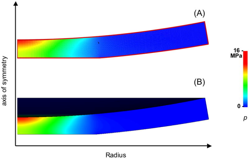
Contour plot of the fluid pressure for (a) the biphasic case and (b) the incompressible-elastic case, for the second analysis.
Figure 6.

Radial normal Lagrangian strain Err for (a) the biphasic case and (b) the incompressible-elastic case, for the second analysis.
Figure 7.

Axial normal Lagrangian strain Ezz for (a) the biphasic case and (b) the incompressible-elastic case, for the second analysis.
DISCUSSION
This study demonstrates from basic principles that the instantaneous response of a biphasic material is equivalent to the response of an incompressible elastic material for arbitrary deformations and material symmetry, and provides practical guidelines for the validity of this equivalence overt the short-term biphasic response. This result generalizes the special cases demonstrated in earlier studies [1, 4, 6–9]. The stress and solid displacement are identical and the interstitial fluid pressure in a biphasic analysis is equal to the hydrostatic pressure in an incompressible elastic analysis everywhere except at permeable boundaries, where the pressure in the biphasic analysis reduces to the prescribed boundary condition (ambient pressure) over an infinitesimally thin boundary layer.
This general result was illustrated with an unconfined compression analysis of a biphasic disk, and with two sample finite deformation contact analyses, using a custom-written biphasic finite element program and the well-validated NIKE3D program, customized to incorporate the desired constitutive relations. The unconfined compression analysis neatly illustrates how the fluid pressure in the incompressible elastic analysis is equal to the pressure p in the biphasic analysis everywhere along r, except in a thin boundary layer near the permeable radial edge (Figure 1). From theory, we know that the boundary layer in a biphasic analysis is infinitely thin at t = 0 +; however, in a numerical implementation such as the one shown here, the biphasic solution is evaluated at a small, but finite time step. Thus, the boundary layer thickness is related to the size of this initial time increment. This example clarifies that if one conducts an incompressible elastic analysis to simulate the instantaneous biphasic response, one should expect to be an accurate representation of p everywhere except at a permeable boundary, where one should (mentally) substitute the solution for with the appropriate boundary condition for p.
The agreement observed in the contact analyses between the two approaches is remarkable, especially considering that the biphasic analysis is based on a 2D axisymmetric implementation in cylindrical coordinates while the NIKE3D analysis is three-dimensional and in Cartesian coordinates. From the contour plots of the pressure (Figure 5), it is evident that the biphasic and elastic analyses yielded nearly identical results everywhere inside the articular layer. The permeable boundaries in the biphasic analysis are the articular surface outside of the contact region, and the lateral edge. Based on the prescribed boundary conditions, the fluid pressure p was set to zero at these locations. In contrast, no boundary condition could be imposed on . Nevertheless, nearly reduced to zero at these boundaries, in close agreement with p (Figure 4). This suggests that, for this type of contact analyses, the instantaneous biphasic and incompressible elastic predictions do not differ appreciably even at permeable boundaries. However, it is important not to generalize this special case to all types of problems, as shown for example in the analysis of unconfined compression in Figure 1.
The results of this study provide a rationale for using available finite element codes for incompressible elastic materials as a practical substitute for biphasic analyses, as long as only the short-time biphasic response is sought. In the application of these analyses to the study of biological tissues, the physiological relevance of the short-time response depends on the problem being examined. As shown in Eq. (52), the characterization of the ‘short-time’ response depends on the modulus, permeability and characteristic dimensions of the tissue. For example, for the above articular cartilage contact problem, (based on the finite element results), ||K|| ~2.7 × 10⁻³ mm4/N.s, and Δ ~ 3 mm (the radius of the contact area [34]), so that the short time response, calculated from these values using Eq. (53), corresponds to δt ≪ 5 s. In other words, the elastic incompressible contact analysis would be representative of biphasic contact analyses where loading occurs over a time span of ~0.5 s or less.
The equivalence between the instantaneous biphasic and incompressible elastic responses is valid for any constitutive model, as long as the biphasic constitutive equations reduce to the incompressible elastic equations when J = 1, as shown for example in Eq. (11). However, depending on the finite element implementation for incompressible elasticity, some limitations may be imposed on the choice of constitutive formulations, as shown in the case of uncoupled strain energy densities. These limitations do not invalidate the general equivalence, but may impose some practical restrictions that should be heeded in any specific application. Indeed, several popular finite element programs, including ABAQUS (ABAQUS, Inc, Providence, RI) and FEAP (University of California, Berkeley), use an uncoupled strain energy implementation for modeling incompressible elastic solids. These restrictions can be overcome as outlined in the methods above, by properly post-processing the results of the incompressible elastic finite element analysis to reproduce the instantaneous biphasic values of p and Te for any desired coupled constitutive relation.
The finite element formulation for the biphasic finite deformation analysis (Eqs. (49)–(50)) is based on a spatial description [23] and differs in its details from the formulations adopted by others [35–39]. It is also presented in a form which accommodates non-Cartesian orthonormal coordinate bases, such as cylindrical and spherical coordinates [40], whereas most formulations are expressed for Cartesian bases, whether explicitly stated or not [23]. In practice, the details of the biphasic finite element implementation may influence the short-time response. As noted above, our implementation yielded an isochoric short-time response only when the discretized form of div v was replaced with a discretized form of (1/J)(DJ/Dt) on the right-hand-side of Eq. (49).
In summary, this study presents a practical alternative for analyzing the short-term response of a biphasic solid-fluid mixture using incompressible elasticity by demonstrating a general equivalence between these two theories under arbitrary deformations. The only difference between the theories occurs in an infinitely thin layer at boundaries where the fluid pressure needs to be prescribed in a biphasic analysis. This theoretical equivalence was demonstrated using finite element analyses of a contact problem representative of articular joints, showing the expected agreement. While the mathematical equivalence is universal, caution must be exercised when selecting constitutive relations which remain physically meaningful if the finite element implementation of the incompressible elastic response employs an uncoupled strain energy formulation.
Figure 2.

Schematic of the axisymmetric finite element contact analysis.
Acknowledgments
This study was supported with funds from the National Institute of Arthritis and Musculoskeletal and Skin Diseases of the National Institutes of Health (AR46532, AR47369) and the Orthopaedic Research and Education Foundation. The authors thank Steve Maas for assistance with the implementation of orthotropic hyperelasticity in NIKE3D.
APPENDIX
Tensor Products
The double contraction operator: is used in a variety of combinations between tensors of various orders [23]. For second order tensors S and T, the contraction is simply S : T = SijTij. For a fourth-order tensor , third order tensor and second-order tensor T, we have , etc. The double contraction of two fourth-order tensors and yields a fourth-order tensor, .
The tensor dyadic products ⊗̄ and ⊗ are defined by [26]
| (A.1) |
| (A.2) |
| (A.3) |
Spatial Elasticity Tensor
In this section we show the relation between the spatial elasticity tensor and the strain energy density W. The 2nd Piola-Kirchhoff stress in the elastic matrix, Se, is obtained from W using
| (A.4) |
where E is the Lagrangian strain tensor, related to C via C = I + 2E. The material elasticity tensor is obtained by differentiating Se with respect to E,
| (A.5) |
The second Piola-Kirchhoff stress is related to the Cauchy stress via
| (A.6) |
To determine the spatial elasticity tensor from Eq. (45), we use the chain rule of differentiation and Eq. (A.5) to evaluate
| (A.7) |
From Eq.(A.6) it can be shown that
| (A.8) |
so that
| (A.9) |
which completes the derivation.
Coupled and Uncoupled Formulations
Using Eqs.(15) and (32), the deviatoric part of the stress tensor Te in a general (coupled) constitutive relation is
| (A.10) |
Similarly, using Eqs.(22), (24) and (36), the deviatoric part of Te in an uncoupled constitutive relation is given by
| (A.11) |
When J = 1, it follows that F̃ = F, C̃ = C and λ̃a = λa. Thus, if W (C) and W̃(C̃)are selected to have the same form, as are Ψa (λa) and Ψ̃a (λ̃a), the coupled and uncoupled formulations will yield identical deviatoric stresses under isochoric deformations.
References
- 1.Mow VC, Kuei SC, Lai WM, Armstrong CG. Biphasic Creep and Stress Relaxation of Articular Cartilage in Compression: Theory and Experiments. J Biomech Eng. 1980;102:73–84. doi: 10.1115/1.3138202. [DOI] [PubMed] [Google Scholar]
- 2.Cohen B, Lai WM, Mow VC. A Transversely Isotropic Biphasic Model for Unconfined Compression of Growth Plate and Chondroepiphysis. J Biomech Eng. 1998;120:491–496. doi: 10.1115/1.2798019. [DOI] [PubMed] [Google Scholar]
- 3.Soulhat J, Buschmann MD, Shirazi-Adl A. A Fibril-Network-Reinforced Biphasic Model of Cartilage in Unconfined Compression. J Biomech Eng. 1999;121:340–347. doi: 10.1115/1.2798330. [DOI] [PubMed] [Google Scholar]
- 4.Soltz MA, Ateshian GA. A Conewise Linear Elasticity Mixture Model for the Analysis of Tension-Compression Nonlinearity in Articular Cartilage. J Biomech Eng. 2000;122:576–586. doi: 10.1115/1.1324669. [DOI] [PMC free article] [PubMed] [Google Scholar]
- 5.Bachrach NM, Mow VC, Guilak F. Incompressibility of the Solid Matrix of Articular Cartilage under High Hydrostatic Pressures. J Biomech. 1998;31:445–451. doi: 10.1016/s0021-9290(98)00035-9. [DOI] [PubMed] [Google Scholar]
- 6.Armstrong CG, Lai WM, Mow VC. An Analysis of the Unconfined Compression of Articular Cartilage. J Biomech Eng. 1984;106:165–173. doi: 10.1115/1.3138475. [DOI] [PubMed] [Google Scholar]
- 7.Brown TD, Singerman RJ. Experimental Determination of the Linear Biphasic Constitutive Coefficients of Human Fetal Proximal Femoral Chondroepiphysis. J Biomech. 1986;19:597–605. doi: 10.1016/0021-9290(86)90165-x. [DOI] [PubMed] [Google Scholar]
- 8.Mak AF, Lai WM, Mow VC. Biphasic Indentation of Articular Cartilage--I. Theoretical Analysis. J Biomech. 1987;20:703–714. doi: 10.1016/0021-9290(87)90036-4. [DOI] [PubMed] [Google Scholar]
- 9.Ateshian GA, Lai WM, Zhu WB, Mow VC. An Asymptotic Solution for the Contact of Two Biphasic Cartilage Layers. J Biomech. 1994;27:1347–1360. doi: 10.1016/0021-9290(94)90044-2. [DOI] [PubMed] [Google Scholar]
- 10.Armstrong CG, Mow VC. Variations in the Intrinsic Mechanical Properties of Human Articular Cartilage with Age, Degeneration, and Water Content. J Bone Joint Surg Am. 1982;64:88–94. [PubMed] [Google Scholar]
- 11.Chahine NO, Wang CC, Hung CT, Ateshian GA. Anisotropic Strain-Dependent Material Properties of Bovine Articular Cartilage in the Transitional Range from Tension to Compression. J Biomech. 2004;37:1251–1261. doi: 10.1016/j.jbiomech.2003.12.008. [DOI] [PMC free article] [PubMed] [Google Scholar]
- 12.Huang CY, Stankiewicz A, Ateshian GA, Mow VC. Anisotropy, Inhomogeneity, and Tension-Compression Nonlinearity of Human Glenohumeral Cartilage in Finite Deformation. J Biomech. 2005;38:799–809. doi: 10.1016/j.jbiomech.2004.05.006. [DOI] [PMC free article] [PubMed] [Google Scholar]
- 13.Kempson GE, Freeman MA, Swanson SA. Tensile Properties of Articular Cartilage. Nature. 1968;220:1127–1128. doi: 10.1038/2201127b0. [DOI] [PubMed] [Google Scholar]
- 14.Hayes WC, Keer LM, Herrmann G, Mockros LF. A Mathematical Analysis for Indentation Tests of Articular Cartilage. J Biomech. 1972;5:541–551. doi: 10.1016/0021-9290(72)90010-3. [DOI] [PubMed] [Google Scholar]
- 15.Eberhardt AW, Keer LM, Lewis JL, Vithoontien V. An Analytical Model of Joint Contact. J Biomech Eng. 1990;112:407–413. doi: 10.1115/1.2891204. [DOI] [PubMed] [Google Scholar]
- 16.Carter DR, Beaupre GS. Linear Elastic and Poroelastic Models of Cartilage Can Produce Comparable Stress Results: A Comment on Tanck Et Al. (J Biomech 32:153–161, 1999) J Biomech. 1999;32:1255–1257. doi: 10.1016/s0021-9290(99)00123-2. [DOI] [PubMed] [Google Scholar]
- 17.Wong M, Carter DR. Theoretical Stress Analysis of Organ Culture Osteogenesis. Bone. 1990;11:127–131. doi: 10.1016/8756-3282(90)90060-c. [DOI] [PubMed] [Google Scholar]
- 18.Bowen RM. Incompressible Porous Media Models by Use of the Theory of Mixtures. Int J Engng Sci. 1980;18:1129–1148. [Google Scholar]
- 19.Huyghe JM, Janssen JD. Quadriphasic Mechanics of Swelling Incompressible Porous Media. Int J Engng Sci. 1997;35:793–802. [Google Scholar]
- 20.Holmes MH, Mow VC. The Nonlinear Characteristics of Soft Gels and Hydrated Connective Tissues in Ultrafiltration. J Biomech. 1990;23:1145–1156. doi: 10.1016/0021-9290(90)90007-p. [DOI] [PubMed] [Google Scholar]
- 21.Lai WM, Mow VC. Drag-Induced Compression of Articular Cartilage During a Permeation Experiment. Biorheology. 1980;17:111–123. doi: 10.3233/bir-1980-171-213. [DOI] [PubMed] [Google Scholar]
- 22.Gu WY, Yao H, Huang CY, Cheung HS. New Insight into Deformation-Dependent Hydraulic Permeability of Gels and Cartilage, and Dynamic Behavior of Agarose Gels in Confined Compression. J Biomech. 2003;36:593–598. doi: 10.1016/s0021-9290(02)00437-2. [DOI] [PubMed] [Google Scholar]
- 23.Bonet J, Wood RD. Nonlinear Continuum Mechanics for Finite Element Analysis. Cambridge University Press; Cambridge: 1997. [Google Scholar]
- 24.Simo JC, Taylor RL, Pister KS. Variational and Projection Methods for the Volume Constraint in Finite Deformation Elastoplasticity. Comput Methods Appl Mech Engrg. 1985;51:177–208. [Google Scholar]
- 25.Weiss JA, Maker BN, Govindjee S. Finite Element Implementation of Incompressible, Transversely Isotropic Hyperelasticity. Comput Methods Appl Mech Engrg. 1996;135:107–128. [Google Scholar]
- 26.Curnier A, He QC, Zysset P. Conewise Linear Elastic Materials. J Elasticity. 1995;37:1–38. [Google Scholar]
- 27.Quapp KM, Weiss JA. Material Characterization of Human Medial Collateral Ligament. J Biomech Eng. 1998;120:757–763. doi: 10.1115/1.2834890. [DOI] [PubMed] [Google Scholar]
- 28.Baer AE, Laursen TA, Guilak F, Setton LA. The Micromechanical Environment of Intervertebral Disc Cells Determined by a Finite Deformation, Anisotropic, and Biphasic Finite Element Model. J Biomech Eng. 2003;125:1–11. doi: 10.1115/1.1532790. [DOI] [PubMed] [Google Scholar]
- 29.Lanir Y. Constitutive Equations for Fibrous Connective Tissues. J Biomech. 1983;16:1–12. doi: 10.1016/0021-9290(83)90041-6. [DOI] [PubMed] [Google Scholar]
- 30.Lanir Y. Biorheology and Fluid Flux in Swelling Tissues, Ii. Analysis of Unconfined Compressive Response of Transversely Isotropic Cartilage Disc. Biorheology. 1987;24:189–205. doi: 10.3233/bir-1987-24211. [DOI] [PubMed] [Google Scholar]
- 31.Laasanen MS, Toyras J, Korhonen RK, Rieppo J, Saarakkala S, Nieminen MT, Hirvonen J, Jurvelin JS. Biomechanical Properties of Knee Articular Cartilage. Biorheology. 2003;40:133–140. [PubMed] [Google Scholar]
- 32.Wayne JS, Woo SL, Kwan MK. Application of the U-P Finite Element Method to the Study of Articular Cartilage. J Biomech Eng. 1991;113:397–403. doi: 10.1115/1.2895418. [DOI] [PubMed] [Google Scholar]
- 33.Maker BN, Ferencz RM, Hallquist JO. Nike3d—a Nonlinear, Implicit, Three-Dimensional Finite Element Code for Solid and Structural Mechanics. 1990 LLNL Technical Report, #UCRL-MA 105268. [Google Scholar]
- 34.Kelkar R, Ateshian GA. Contact Creep of Biphasic Cartilage Layers. Journal of Applied Mechanics, Transactions ASME. 1999;66:137–145. [Google Scholar]
- 35.Almeida ES, Spilker RL. Mixed and Penalty Finite Element Models for the Nonlinear Behavior of Biphasic Soft Tissues in Finite Deformation: Part I - Alternate Formulations. Comput Methods Biomech Biomed Engin. 1997;1:25–46. doi: 10.1080/01495739708936693. [DOI] [PubMed] [Google Scholar]
- 36.Levenston ME, Frank EH, Grodzinsky AJ. Variationally Derived 3-Field Finite Element Formulations for Quasistatic Poroelastic Analysis of Hydrated Biological Tissues. Comput Methods Appl Mech Engrg. 1998;156:231–246. [Google Scholar]
- 37.Suh JK, Spilker RL. Penalty Finite Element Analysis for Non-Linear Mechanics of Biphasic Hydrated Soft Tissue under Large Deformation. Int J Num Meth Eng. 1991;32:1411–1439. [Google Scholar]
- 38.Diebels S, Ehlers W. Dynamic Analysis of a Fully Saturated Porous Medium Accounting for Geometrical and Material Non-Linearities. Int J Num Meth Eng. 1996;39:81–97. [Google Scholar]
- 39.Simon BR, Kaufmann MV, McAfee MA, Baldwin AL. Finite Element Models for Arterial Wall Mechanics. J Biomech Eng. 1993;115:489–496. doi: 10.1115/1.2895529. [DOI] [PubMed] [Google Scholar]
- 40.Meng XN, LeRoux MA, Laursen TA, Setton LA. A Nonlinear Finite Element Formulation for Axisymmetric Torsion of Biphasic Materials. Int J Solids Struct. 2002;39:879–895. [Google Scholar]