Abstract
An accurate analysis and quantification of microdamage is critical to understand how microdamage affects the mechanics and biology of bone fragility. In this study we demonstrate the development and validation of a novel in vitro micro-computed tomography (microCT) method that employs lead-uranyl acetate as a radio-opaque contrast agent for automated quantification of microdamage in trabecular bone. Human trabecular bone cores were extracted from the femoral neck, scanned via microCT, loaded in unconfined compression to a range of apparent strains (0.5% to 2.25%), stained in lead-uranyl acetate, and subsequently re-scanned via microCT. An investigation of the regions containing microdamage using backscatter mode of a scanning electron microscope (BSEM) showed that the lead-uranyl sulfide complex was an effective contrast agent for microdamage in bone. Damage Volume per Bone Volume (DV/BV), as determined by microCT, increased exponentially to applied strains and proportionately to mechanically determined modulus reduction (p<0.001). Furthermore, the formation of microdamage was observed to occur before any apparent stiffness loss suggesting that the localized tissue yielding occurs prior to the structural yielding of trabecular bone. This non-invasive in vitro technique for the detection of microdamage may serve as a valuable complement to existing morphometric analyses of bone via microCT.
Keywords: trabecular bone, microdamage, microCT, bone imaging, bone histomorphometry
Introduction
The formation of microdamage in engineering materials often denotes the initiation of failure [1], and in bone, this is no exception. More importantly, the in vivo formation of microdamage initiates the bone repair process through remodeling [2]. The inability for bone to effectively repair damaged regions subsequently leads to the accumulation of microdamage, which been known to adversely impact the mechanical behavior of bone and reduce its fracture resistance [3-6]. Morphologies of microdamage and the localization of these morphologies also play a role in determining the age-related fragility of cortical bone [7]. For example, the formation of damage morphologies has been shown to preferentially co-localize and optimize fracture resistance [6]. Age-related biochemical changes in bone [8,9] may also reduce the effectiveness of this damage mechanism, leading to increased bone fragility [6,7]. The ability to effectively assess the formation, morphology, and accumulation of microdamage is therefore critical to the understanding the age-related increase of bone fragility.
In cancellous bone, the understanding of microdamage is further confounded by the complexities of trabecular architecture and its interactions with loading [10,11]. Thus in order to fully understand the effects and localization of microdamage formation, it is necessary to develop a method to characterize and quantify microdamage that would also capture architectural information. Typically, microdamage labeling of bone is done through en bloc staining, followed by thin sectioning and assessment by optical microscopy [12]. While this method is considered to be the gold standard in bone microdamage labeling, there are clear disadvantages to this method: the irrecoverable destruction of the sample; the limited 2-dimensional visualization of damage morphology; and the subjective and often laborious process of microdamage characterization and quantification.
MicroCT scanners are able to capture the structural and mineralization information, but may be limited in their spatial resolution. Current microCT scanners are capable of detecting microcracks in bone [13], but radio-opaque contrast agents are needed for the detection of structurally non-discrete diffuse microdamage. Heavy-metal stains such as barium sulfate and iodine-based contrast agents have been proposed [14,15], however, the use of these stains is in developmental stages, and has not been fully validated for three-dimensional analysis. Traditionally used in SEM histological preparation [16,17], lead-uranyl acetate has been shown to stain for microdamage in bone [18] and could therefore be an ideal stain for other radiological applications. Thus, the objective of this study was to apply and validate lead-uranyl acetate staining for microCT-based detection of microdamage in trabecular bone.
Methods
Nine cancellous bone cores were extracted from the left and right femurs of a seventy-eight year old male, who was free of Hepatitis B, HIV, and known metabolic bone diseases (NDRI, Phildelphia, PA).
A drill press with a modified jig was used to obtain cancellous bone cores from the femoral head. An X-Ray of each femur was taken to determine the principal trabeculae orientation, and the cores of 8-mm diameter were taken longitudinally along this direction. The cancellous bone cores were cut into 8-10mm segments using the ISOMET 11-1180 low-speed diamond blade saw (Buehler Corp., Lake Bluff, IL). The length and diameter of each core was measured using a caliper taken at thirty-degree rotations, and these measurements were averaged.
Prior to mechanical testing, each specimen was scanned using the Scanco Viva-CT 40 scanner (Scanco Medical AG, Bassersdorf, Switzerland) to determine its control state. The microCT scanner was operated at the peak energy of 70kVp, current of 114μA, integration time of 381ms, and a 10μm voxel resolution.
Mechanical testing was conducted using MTS Bionix 858 hydraulic servo mechanical testing station (MTS, Eden Prairie, MN). Using a thin layer of cyanoacrylate glue, each specimen was glued to the brass end caps as previously described [19,20] and loaded in unconfined compression at 100 με/s at 37°C under constant hydration; strains were computed from an extensometer that measured the relative displacement of the end caps. One specimen was designated as control and did not undergo mechanical loading, and eight specimens were respectively loaded to strains of 0.50%, 0.75%, 1.00%, 1.25%, 1.50%, 1.75%, 2.00%, and 2.25%. From the resulting stress-strain data, a number of variables were computed to estimate the modulus reduction. The tangent modulus (Etan) was defined as the maximum slope of an 11-piece linear regression of the stress-strain curve between the applied apparent strains of 0.1% and 0.8% [19-21]. The secant modulus (Esec) was determined as the slope between the end of the loading regime and the initial point at 0% strain. The modulus reduction was determined by the change in stiffness as given by 1-Esec/Etan.
Following mechanical testing, all nine specimens, including the unloaded specimen, were immersed in a solution of 70% acetone containing a lead-uranyl acetate complex for the staining of microdamage. For this purpose, a previously published protocol by Schaffler et al. [18] was modified to include a 14-day immersion of specimens in equal mixtures of 20% lead acetate in 70% acetone and 8% uranyl acetate in 70% acetone. The samples were subsequently immersed in 1% ammonium sulfide in acetone for 7 days [16-18]. To ensure even mixing, the solution-immersed specimens were placed on a shaker for at least one hour a day.
Each stained specimen was then scanned using the Scanco Viva-CT 40 (Scanco Medical AG, Bassersdorf, Switzerland) at the same operating conditions mentioned above. Threshold values for bone and lead-uranyl acetate were empirically determined based on their respective attenuation properties. Component labeling analysis was done using the Image Processing Language version 4.3 (Scanco Medical AG, Bassersdorf, Switzerland) in order to remove the random dispersion of the lead-uranyl sulfide stains not associated with any trabecular structure, and all computations are based on the primary components of this analysis (typically accounting for 99% of all damaged elements). Damaged Volume per Bone Volume (DV/BV), or damaged volume fraction, for the mechanically tested samples was computed as the ratio the number of stained elements to the total number of elements (DV/TV), divided by the bone volume fraction (BV/TV). In order to account for the possible artifacts of microdamage induced in the cancellous bone cores during the cutting process, damage computations were based a central 4mm volumetric cube, away from the initial circumference of the cylinder. In the unloaded control sample, the microCT-measured DV/BV value was used as a baseline for the in vivo accumulation of microdamage and possible artifacts of due to staining [18]. The fraction determined from the control sample was subtracted from subsequent DV/BV values determined from loaded samples.
A Carl-Zeiss Supra SEM 60 (Carl Zeiss SMT, Thornwood, New York, USA) with X-Ray crossbeam was used to obtain elemental compositions at crack sites, and a backscatter detector was used to radiologically differentiate stained regions from non-stained regions.
One-way ANOVA was used to ascertain the effect of staining on BV/TV measurements. Regression analysis was used to examine the relationships between the variables of interest. All statistical analyses were performed using the statistical package, SigmaSTAT 2.0 (SPSS, Chicago, IL).
Results
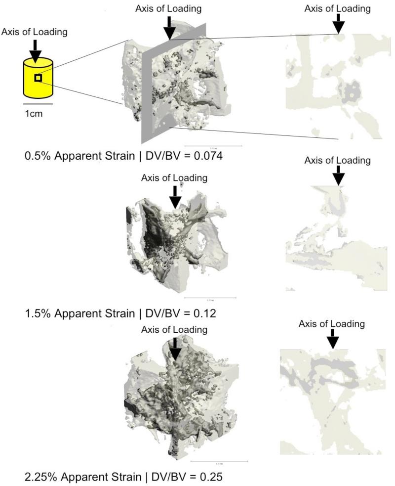
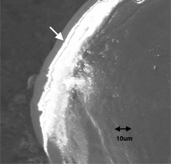
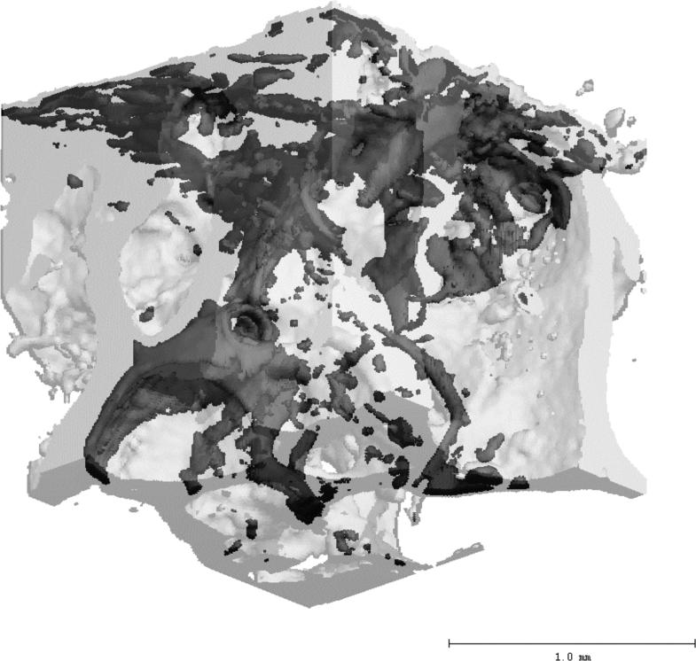
MicroCT was able to detect the increasing progression of microdamage with increasing applied strains as seen by both the 3D and 2D images (Figure 1). EDX analysis confirmed the presence of both lead and uranium in regions of cracks; these elements were not detected in regions with no cracks. Back-scattered SEM shows the association of the lead-uranyl sulfide complex with linear microcracks and diffuse microdamage (Figure 2). A 3-dimensional reconstruction using Scanco software Eval 5.0 shows a three-dimensional rendering of a bone volume (Figure 3), with the lead-uranyl acetate stained regions highlighted. There were no differences in BV/TV before and after lead-uranyl acetate staining (p = 0.75; ANOVA).
Figure 1.
MicroCT detection of increased DV/BV with increasing apparent strains. The left column shows a 3D reconstruction from a central volumetric cube of the cancellous bone cores loaded to respective strains. The right column shows a longitudinal cross-section along the axis of loading from the corresponding the respective volumes on the left. While DV/BV was computed based on the 4mm3 center cubes, the 3D views shown here are based on 1.5mm3 cubes for the ease of visualization. The darker shade of gray indicates regions stained by lead-uranyl sulfide as detected by microCT, while the lighter shade show unlabeled bone.
Figure 2.
Back-scattered SEM image showing the presence of lead-uranyl acetate around the long crack (white arrow) and in the surrounding region of diffuse microdamage.
Figure 3.
A 2mm cubic volume showing damaged regions which has been labeled with lead-uranyl sulfide. The darker shade of gray indicates regions stained by lead-uranyl sulfide as detected by microCT, while the lighter shade shows unlabelled bone.
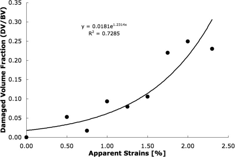
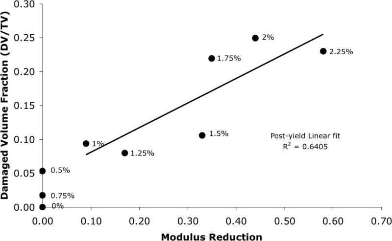
DV/BV, determined from microCT, increased exponentially with the applied apparent strain in each sample (p<0.001; Figure 4), while the modulus reduction, determined from mechanical tests, showed a high linear correlation with the applied strain only after the expected yield point (r214 =0.98; Figure 5). Consequently, a strong linear correlation was found between DV/BV and post-yield modulus reduction (r2=0.64; Figure 6).
Figure 4.
MicroCT determined damage volume fraction (DV/BV) increased exponentially to the applied apparent strains in the cancellous bone cores (Pearson correlation; p<0.001).
Figure 5.
Mechanically determined modulus reduction increased proportionally to the applied apparent strains in cancellous bone cores after the onset of yielding (r2=0.98).
Figure 6.
Damage volume fraction (DV/BV) increased proportionately to the modulus reduction in the cancellous bone cores (r2=0.64). The applied apparent strain for each sample is shown beside the respective points.
Discussion
Through the use of microCT, EDXA, backscattered SEM, 2 and mechanical testing, this study demonstrates the successful development and application of a novel microCT-based technique for radiological detection and quantification of trabecular bone microdamage. Using lead-uranyl acetate to selectively label the regions of bone damage formation, total microdamage accumulation can now be captured by a single metric, Damaged Volume per Bone Volume (DV/BV). Unlike stereological measures of damaged regions, which are discrete estimators for damaged volume, DV/BV is a true volumetric measure of microdamage [22].
DV/BV, as measured by microCT, exhibited a significant exponential increase with applied apparent strains for all samples (Figure 4). Using this technique, the increase of DV/BV with increasing application of strains can be visually confirmed (Figure 1). Consistent with previous works, this trend indicates the increasing accumulation of loading-induced microdamage with increasing strains in trabecular bone. [5,13,23]. Because cancellous bone samples were mechanically tested using artifact-free methods [19,20], measurements of modulus reduction and applied strains can be assured to be accurate. Furthermore, because the samples from this study were taken from a single donor and from the same anatomical location, the variations in mechanical behavior due to matrix quality [9] and architectural differences [24] should be minimal.
As a composite material, bone derives much of its fracture resistance through energy dissipation mechanisms such as the formation of microdamage [25]. The initial increase of DV/BV before the onset of observable modulus loss (Figure 6) is an indicator that the microdamage formation initiates prior to the structural yielding of the cancellous bone volume, and suggests that some regions of the cancellous bone tissue undergo yielding prior to the structural yielding at the apparent level. Specifically, it has been previously demonstrated that localized tissue strains can exceed the applied apparent level strains [26] and cause localized yielding in the form of microdamage, as was detected here in this study. It is also likely that the initial localized yielding allows the trabecular bone structure to remain intact and to dissipate energy by resisting the propagation of catastrophic damage [25,27], and decreases the likelihood of trabecular microfractures [28]. The damage process zones marks the site of structural failure and is identifiable by diffuse staining [18]. However, as the applied strains increase, microcracks within the damage zone coalesce [25] and subsequently cause the collapse of the cancellous bone structure [29].
It has been found that the elastic modulus is the least sensitive parameter to indicate mechanical overload [30], and this insensitivity is likely to influence the values of modulus reduction because the latter is computed based on the elastic modulus. By definition, loading in the linear range results in zero modulus reduction because the final modulus is the same as the initial modulus. Thus, any loading prior to any non-linear behavior on the stress strain curve will subsequently result in zero modulus reduction, independently of the amount of physical microdamage that has accumulated in the material. Hence, no relationship between DV/BV and modulus reduction was seen at the early onset of loading in which the specimen exhibited linear behavior (Figures 5, 6). However, once the specimen was loaded to a point of appreciable deviation from the initial linear behavior, or yielding in this case, the correlation between DV/BV and modulus reduction became significant.
In the context of mechanical modulus reduction, also known as damage fraction, (D=1- 1-Eeffective/E), many definitions have been proposed for the “effective modulus” term (Eeffective), including a reloading modulus [29], loading-unloading intersection modulus [3], a “perfect damage” modulus [31,32], a stress-divided-by-strain secant modulus [5], and anelastic-recovery protocol accounting for viscoelastic effects [33]. All but the secant modulus method [5] requires subsequent load cycles, which would cause additional microdamage formation. Consequently, to preserve the initial strain-dependent microdamage formation, we selected the secant modulus method for this study.
Despite the use of bone tissue from a single donor, there is evidence in the literature that lends support to the DV/BV values reported in this study. Previous studies have found that in vivo microdamage accumulation in human vertebral cancellous bone ranged from 15% to 50% diffused damaged area per bone area (DxA/BA) [34]; and the in vivo microdamage accumulation in cancellous bone of the proximal femur was found to be as high as 4% DxA/BA [35]. Furthermore, FEM analysis suggests that cancellous bone loaded to 2% apparent strains results in microdamage formation in up to 80% of the trabeculae [11]. In contrast to these findings, the ex vivo compression of bovine trabecular bone resulted in DxA/BA ranging from 0.1% - 3% [29]. The differences between the studies on human bone including our study and the Moore and Gibson's study on bovine bone can be explained by variations in architecture, apparent density, and matrix quality. All these factors may play a significant role in determining the magnitude and extent of microdamage formation [36,37]. For example, the behavior of trabecular bone can vary greatly between species and anatomic site [36]. It is therefore not surprising that the elderly human bone from the proximal femur, a lower density bone, would be more susceptible to accumulation of loading-2 induced microdamage than young bovine tibial bone, a higher density bone. Despite these differences, the exponential increase in DV/BV (Fig. 4) due to apparent strains found in this study is consistent with the trends found in bovine bone [29], suggesting that the mechanism of damage accumulation may be similar between the two species.
There are several limitations in this study. The first and foremost, this microCT technique, in its current form, is unable to differentiate between microcracks and diffuse microdamage [38,39]. Additional work needs to be done in order to develop proper segmentation and analysis techniques that would allow the automated detection of different microdamage morphologies. Furthermore, because microcracks typically have tip openings on the order of 1 μm, this current microCT technique may be limited by the spatial resolution of the scanner. Secondly, the accuracy of DV/BV measurements may be affected by the use of a low-power X-Ray source which may overestimate the presence of atomically heavy compounds such as lead-uranyl sulfide and further confound the systematic partial volume effects. The use of scanners employing higher powered sources, such as Synchrotron radiation, may greatly improve the accuracy of detection [40]. Another source of error may come from the staining of microstructural components such as osteoid seams and canaliculi [18]. However, we have attempted to control for these potential artifacts by staining an unloaded sample and subtracting the resulting number of stained elements from loaded samples and assuming that the amount of stained osteoid seams and canaliculi remain relatively constant in a equal volume of cancellous bone from a single anatomic site within one donor. Similarly, by basing the DV/TV measures on away from the edges of the cutting surface, we can exclude microdamage that may have resulted from sample preparation. 2 Lastly, the local variations in apparent density within the same donor may have also affected our cancellous bone mechanical measurements. Previous studies have shown that trabecular architecture exhibits heterogeneities between anatomical locations [37,41,42] and can be a source of error in testing cancellous bone. Our experimental design, however, allows us to account for some of the site-specific heterogeneities by extracting the cancellous bone cores from the same anatomical location and using end-artifact free testing protocols [19,20]. Nevertheless, intra-site differences in apparent density may have contributed to some variations in the mechanical behavior.
In conclusion, this study demonstrates the successful development and application of a novel microCT-based technique for radiological detection and quantification of trabecular bone microdamage. This non-invasive in vitro technique for the detection of microdamage may serve as a valuable complement to existing morphometric analyses of bone via microCT.
Acknowledgements
This study was supported by NIH Grant AR49635. 2 The human tissue samples were obtained from NDRI.
Footnotes
Publisher's Disclaimer: This is a PDF file of an unedited manuscript that has been accepted for publication. As a service to our customers we are providing this early version of the manuscript. The manuscript will undergo copyediting, typesetting, and review of the resulting proof before it is published in its final citable form. Please note that during the production process errors may be discovered which could affect the content, and all legal disclaimers that apply to the journal pertain.
References
- 1.Krajcinovic D. Continuum damage mechanics. Appl Mech Rev. 1984;37:1–5. [Google Scholar]
- 2.Mori S, Burr DB. Increased intracortical remodeling following fatigue damage. Bone. 1996;14(2):103–9. doi: 10.1016/8756-3282(93)90235-3. [DOI] [PubMed] [Google Scholar]
- 3.Zioupos P, Currey JD, Sedman AJ. An examination of the micromechanics of failure of bone and antler by acoustic emission tests and Laser Scanning Confocal Microscopy. Med Eng Phys. 1994;16(3):203–12. doi: 10.1016/1350-4533(94)90039-6. [DOI] [PubMed] [Google Scholar]
- 4.Burr DB, Turner CH, Naick P, Forwood MR, Ambrosius W, Hasan MS, Pridaparti R. Does microdamage accumulation affect the mechanical properties of bone? J Biomech. 1998;21(1998):337–45. doi: 10.1016/s0021-9290(98)00016-5. [DOI] [PubMed] [Google Scholar]
- 5.Morgan EF, Yeh OC, Keaveny TM. Damage in trabecular bone at small strains. Eur J Morphol. 2005 Feb-Apr;42(1-2):13–21. doi: 10.1080/09243860500095273. [DOI] [PubMed] [Google Scholar]
- 6.Diab T, Vashishth D. Effects of damage morphology on cortical bone fragility. Bone. 2005;37(1):96–102. doi: 10.1016/j.bone.2005.03.014. [DOI] [PubMed] [Google Scholar]
- 7.Diab T, Condon KW, Burr DB, Vashishth D. Age-related change in damage morphology of human cortical bone and its role in bone fragility. Bone. 2006;38(3):427–31. doi: 10.1016/j.bone.2005.09.002. [DOI] [PubMed] [Google Scholar]
- 8.Wang X, Shen X, Li X, Agrawal CM. Age-related changes in the collagen network and toughness of bone. Bone. 2002 Jul;31(1):1–7. doi: 10.1016/s8756-3282(01)00697-4. [DOI] [PubMed] [Google Scholar]
- 9.Bloebaum RD, Lundeen GA, Shea JE, Whitaker EL. Age-related mineralization heterogeneity changes in trabecular bone of the proximal femur. Anat Rec A Discov Mol Cell Evol Biol. 2004;281(2):1296–302. doi: 10.1002/ar.a.20079. [DOI] [PubMed] [Google Scholar]
- 10.Wachtel EF, Keaveny TM. Dependence of trabecular damage on mechanical strain. J Ortho Res. 1997;15:781–787. doi: 10.1002/jor.1100150522. [DOI] [PubMed] [Google Scholar]
- 11.Yeh OC, Keaveny TM. Relative roles of microdamage and microfracture in the mechanical behavior of trabecular bone. J Orthop Res. 2001;19(6):1001–7. doi: 10.1016/S0736-0266(01)00053-5. [DOI] [PubMed] [Google Scholar]
- 12.Burr DB, Hooser M. Alterations to the en block basic fushin staining protocol for the demonstration of microdamage produced in vivo. Bone. 1995 1995 Oct;17(4):431–3. doi: 10.1016/s8756-3282(95)00241-3. [DOI] [PubMed] [Google Scholar]
- 13.Nagaraja S, Tracey CL, Guldberg RE. Trabecular bone microdamage and microstructural stresses under uniaxial tension. J. Biomech. 2005;38(3005):707–16. doi: 10.1016/j.jbiomech.2004.05.013. [DOI] [PubMed] [Google Scholar]
- 14.Wang X, Leng H, Roeder RK, Niebur GL. Three-dimensional imaging of microdamage in bone using microCT.. ASME Bioengr. Conf..2005. [Google Scholar]
- 15.Parkesh R, Lee CT, Gunnlaugsson T, Gowin W. Microdamage in bone: Surface analysis and radiological detection. J Biomech. 2006;39(8):1552–6. doi: 10.1016/j.jbiomech.2005.04.003. [DOI] [PubMed] [Google Scholar]
- 16.Gimenez-Martin G, Risueno MC. A simple staining technique for electron microscopy with lead-uranyl acetate. Separatum Experientia. 1967;23:316–318. doi: 10.1007/BF02135708. [DOI] [PubMed] [Google Scholar]
- 17.Sheehan DC, Hrapchak BB. Theory and practice of histotechnology. Mosby; St. Louis, MO: 1980. pp. 327–346. [Google Scholar]
- 18.Schaffler MB, Pitchford WC, Choi K, Riddle JM. Examination of compact bone microdamage using back-scattered electron microscopy. Bone. 1994 Sep-Oct;15(5):483–8. doi: 10.1016/8756-3282(94)90271-2. [DOI] [PubMed] [Google Scholar]
- 19.Hou FJ, Lang SM, Hoshaw SJ, Reimann DA, Fyhrie DP. Human vertebral body apparent and hard tissue stiffness. J Biomech. 1998 Nov;31(11):1009–15. doi: 10.1016/s0021-9290(98)00110-9. [DOI] [PubMed] [Google Scholar]
- 20.Fyhrie DP, Vashishth D. Bone stiffness predicts strength similarly for human vertebral cancellous bone in compression and for cortical bone in tension. Bone. 2000 Feb;26(2):169–73. doi: 10.1016/s8756-3282(99)00246-x. [DOI] [PubMed] [Google Scholar]
- 21.ASTM E8M-1998 Standard test methods for tension testing of metallic materials (metric). Annual Book of American Society for Testing of Metal Standards. 1998 [Google Scholar]
- 22.Cowin SC. The relationship between the elasticity tensor and the fabric tensor. Mech. Mater. 1985;4:137–47. doi: 10.1016/j.mechmat.2012.07.004. [DOI] [PMC free article] [PubMed] [Google Scholar]
- 23.Fazzalari NL, Forwood MR, Manthey BA, Smith K, Kolesik P. Three-dimensional confocal images of microdamage in cancellous bone. Bone. 1998;23(4):373–8. doi: 10.1016/s8756-3282(98)00111-2. [DOI] [PubMed] [Google Scholar]
- 24.Morgan EF, Bayraktar HH, Yeh OC, Majumdar S, Burghard t A, Keaveny TM. Contribution of inter-site variations in architecture to trabecular bone apparent yield strains. J Biomech. 2004;37(9):1413–20. doi: 10.1016/j.jbiomech.2003.12.037. [DOI] [PubMed] [Google Scholar]
- 25.Vashishth D, Behiri JC, Bonfield W. Crack growth resistance in cortical bone: Concept of microcrack toughening. J. Biomech. 1997;30(8):763–9. doi: 10.1016/s0021-9290(97)00029-8. [DOI] [PubMed] [Google Scholar]
- 26.Keaveny TM, Guo XE, Wachtel EF, McMahon TA, Hayes WC. Trabecular bone exhibits fully linear elastic behavior and yields at low strains. J Biomech. 1994;27(9):1127–36. doi: 10.1016/0021-9290(94)90053-1. [DOI] [PubMed] [Google Scholar]
- 27.Akkus O, Rimnac CM. Cortical bone tissue resists fatigue fracture by deceleration and arrest of microcrack growth. J Biomech. 2002 Jun;34(6):757–64. doi: 10.1016/s0021-9290(01)00025-2. 2001. [DOI] [PubMed] [Google Scholar]
- 28.Mosekilde L. Consequences of the remodelling process for vertebral trabecular bone structure: a scanning electron microscopy study (uncoupling of unloaded structures). Bone Miner. 1990;10:13–35. doi: 10.1016/0169-6009(90)90046-i. [DOI] [PubMed] [Google Scholar]
- 29.Moore TLA, Gibson LJ. Microdamage accumulation in bonvine trabecvular bone in uniaxial compression. J Biomech Eng. 2002;124(2004):63–71. doi: 10.1115/1.1428745. [DOI] [PubMed] [Google Scholar]
- 30.Morgan EF, Lee JJ, Keaveny TM. Sensitivity of multiple damage parameters to compressive overload in cortical bone. J Biomech. Eng. 2005;127:557–562. doi: 10.1115/1.1933916. [DOI] [PubMed] [Google Scholar]
- 31.Courtney AC, Hayes WC, Gibson LJ. Age-related differences in post-yield damage in human cortical bone: experiment and model. J Biomech. 1996;29:1463. doi: 10.1016/0021-9290(96)84542-8. [DOI] [PubMed] [Google Scholar]
- 32.Keaveny TM, Wachtel EF, Kopperdahl DL. Mechanical behavior of human trabecular bone after overloading. J Orthop Res. 1999 May;17(3):346–53. doi: 10.1002/jor.1100170308. [DOI] [PubMed] [Google Scholar]
- 33.Jepsen KJ, Davy DT. Comparison of damage accumulation measures in human cortical bone. J Biomech. 1997;30:825. doi: 10.1016/s0021-9290(97)00036-5. [DOI] [PubMed] [Google Scholar]
- 34.Vashishth D, Koontz J, Qiu SJ, Lundin-Cannon D, Yeni YN, Schaffler MB, Fyhrie DP. In vivo diffuse damage in human vertebral trabecular bone. Bone. 2000;26(2):147–52. doi: 10.1016/s8756-3282(99)00253-7. [DOI] [PubMed] [Google Scholar]
- 35.Fazzalari NL, Forwood MR, Smith K, Manthey BA, Herreen P. Assessment of cancellous bone quality in severe osteoarthrosis: Bone mineral density, mechanics, and microdamage. Bone. 1998;22(4):381–8. doi: 10.1016/s8756-3282(97)00298-6. [DOI] [PubMed] [Google Scholar]
- 36.Haddock SM, Yeh OC, Mummaneni PV, Rosenberg WS, Keaveny TM. Similarity in the fatigue behavior of trabecular bone across site and species. J Biomech. 2004 Feb;37(2):181–7. doi: 10.1016/s0021-9290(03)00245-8. [DOI] [PubMed] [Google Scholar]
- 37.Morgan EF, Keaveny TM. Dependence of yield strain of human trabecular bone on anatomic site. J Biomech. 2001;34(5):569–77. doi: 10.1016/s0021-9290(01)00011-2. [DOI] [PubMed] [Google Scholar]
- 38.Wenzel TE, Schaffler MB, Fyhrie DP. In vivo trabecular microcracks in human vertebral bone. Bone. 1996 Aug;19(2):89–95. doi: 10.1016/8756-3282(96)88871-5. [DOI] [PubMed] [Google Scholar]
- 39.Vashishth D, Gibson GJ, Khoury JI, Schaffler MB, Kimura J, Fyhrie DP. Influence of Nonenzymatic Glyation on Biomechanical Properties of Cortical Bone. Bone. 2001;22(2):195–201. doi: 10.1016/s8756-3282(00)00434-8. [DOI] [PubMed] [Google Scholar]
- 40.Thurner PJ, Wyss P, Voide R, Stauber M, Stampanoni M, Sennhauser U, Müller R. Time-lapsed investigation of three-dimensional failure and damage accumulation in trabecular bone using synchrontron light. Bone. 2006;39(2):289–99. doi: 10.1016/j.bone.2006.01.147. [DOI] [PubMed] [Google Scholar]
- 41.Catanese J, 3rd, Iverson EP, Ng RK, Keaveny TM. Heterogeneity of the mechanical properties of demineralized bone. J. Biomech. 1999;32(12):1365–9. doi: 10.1016/s0021-9290(99)00128-1. [DOI] [PubMed] [Google Scholar]
- 42.Hernandez CJ, Beaupre GS, Keller TS, Carter DR. The influence of bone volume fraction and ash fraction on bone strength and modulus. Bone. 2001;(29):74–8. doi: 10.1016/s8756-3282(01)00467-7. [DOI] [PubMed] [Google Scholar]


