

Abstract
There is a need for, and utility in, the acquisition of data sets of cardiac histoanatomy, with the vision of reconstructing individual hearts on the basis of noninvasive imaging, such as MRI, enriched by reference to detailed atlases of serial histology obtained from representative samples. These data sets would be useful not only as a repository of knowledge regarding the specifics of cardiac histoanatomy, but could form the basis for generation of individualized high-resolution cardiac structure–function models. The current article presents a step in this general direction: it illustrates how whole-heart noninvasive imaging can be combined with whole-heart histology in an approach to achieve automated construction of histoanatomically detailed models of cardiac 3D structure and function at hitherto unprecedented resolution and accuracy (based on 26.4 × 26.4 × 24.4 μm MRI voxel size, and enriched by histological detail). It provides an overview of the tools used in this quest and outlines challenges posed by the approach in the light of applications that may benefit from the availability of such data and tools.
Keywords: noninvasive imaging, MRI, serial histology, three-dimensional histoanatomy, cardiac modeling, personalized medicine
INTRODUCTION
The heart is a highly heterogeneous structure, with intrinsic differences in cell type distribution, complex electromechanical properties, and an organized activation sequence. It appears that properly integrated function at the whole organ level arises from, and necessarily requires, the concerted interplay of intrinsic structure–function gradients.1 Any change in this well-orchestrated heterogeneity (be it an increase, or indeed a decrease)2 may have detrimental effects on cardiac function.
In terms of major cell populations, the largest volume of cardiac tissue is occupied by myocytes, while fibroblasts dominate in terms of cell numbers.3 We have recently shown that these heterogeneous cells are able to communicate directly via gap junctions.4 In addition, both cardiac myocytes and nonmyocytes are stretch-sensitive, thereby contributing to the functional interaction of cardiac mechanics, electrophysiology, and structure.5 Finally, relative cell content, distribution, and coupling change significantly during both physiological and pathological remodeling of myocardium, which makes the (ideally noninvasive) identification of cardiac histoanatomical features an important target for fundamental research and clinical application.6
Nonetheless, even after more than a century of studies into ventricular tissue architecture,7,8 there is still controversy about apparently basic issues, such as whether or not there is a “unique band” arrangement of myocardial fibers throughout the heart.9,10 This seems surprising since cardiac fiber orientation plays crucial roles in physiologically and clinically relevant functions affecting electrical conduction,11,12 inducibility of arrhythmias,13,14 electrical defibrillation,15,16 contraction and relaxation,17,18 and coronary perfusion.19,20 The lack of definite insight may be explained by the fact that traditional histological techniques are very time consuming and, hence, often conducted on tissue fragments only. This, in combination with their “destructive” nature (in terms of tissue preparation and sectioning), has thus far made routine reconstruction of individual hearts impossible.
With the improvement of both spatial and temporal resolution of novel imaging techniques, issues such as the one outlined above have begun to be addressed via nondestructive assessment of cardiac anatomy and tissue architecture.6,21 Magnetic resonance imaging (MRI), and diffusion tensor MRI (DTMRI) in particular, have demonstrated significant promise in providing reliable data on both cardiac fiber and sheet architecture with a resolution that allows computational reintegration into anatomically based models of mammalian ventricles.18,22 MRI investigations can be conducted in a fraction of the time required for traditional serial sectioning-based histology. In addition, nondestructive imaging is ultimately aimed at in situ assessment of living tissue (even though method development is often conducted ex vivo, in fixed samples), where a combination of advanced scanning protocols and computational postprocessing23–25 makes it increasingly possible to address challenges posed by motion, and to extract functional, rather than “merely” structural, data.
Drawbacks of MR-based cardiac tissue reconstruction include the still limited spatial resolution which, in recent studies, has been 156 μm × 312 μm × 2 mm (DTMRI, rabbit),26 350 μm × 350 μm × 800 μm (DTMRI, canine),27 1 mm × 1 mm × 4 mm (DTMRI, pig heart),10 and 800 μm × 800 μm × 2 mm (spin-echo MRI, man)28 (the first two numbers describe resolution in-plane, the third number relates to interplane distance/out-of-plane resolution). Also, there are still significant challenges in how these data are processed in terms of segmentation, calculation of fiber direction, and computational grid generation.27,29,30
Furthermore, histological validation of MRI and DTMRI data has remained incomplete, as previous work focused on using discrete tissue plugs extracted from various cardiac locations and subsequently related back to approximately matching volumes in the MRI data.18,26,31 Consequently, current cardiac data sets, obtained using the above techniques, do not tend to include the atria, papillary muscles, trabeculae, or segmentation of tissue for different cell populations. Furthermore, while previous efforts to identify the topology of vascular networks,32 including the coronary vessel trees, have provided morphometric information to define connectivities, radii, and segment lengths,33–36 data on the spatial distribution of vessels within a tissue (recently characterized for the renal circulation)37 are still missing.
Clearly, there is a great need for, and utility in, the acquisition of detailed data sets of cardiac histoanatomy. Individual hearts could be reconstructed on the basis of MRI, and enriched by reference to serial histology-based information, to thereby provide high-detail validated information on cardiac geometry, fiber and sheet orientation, cell populations, and a wealth of cardiac microstructural detail. Combining MRI and traditional histological sectioning to achieve this would combine “the best of both worlds”: (i) MRI to generate three-dimensional (3D) histoanatomical organ features that guide image stack alignment and compensate nonlinear distortions; and (ii) histology to increase spatial resolution and discriminate cell populations and a-cellular connective tissue.
The acquired data sets will be useful not only as a repository of knowledge regarding the specifics of cardiac histoanatomy, but as the basis for the generation of high-resolution cardiac structure–function models. Indeed, computational meshes could be generated from these data sets, and functional characteristics of various cell types could be incorporated in the models, providing an unprecedented opportunity to elucidate previously unresolved issues related to cardiac mechanics, electrical behavior, or hemodynamics.
The current article presents a step in this general direction: it illustrates how whole-heart noninvasive imaging can be combined with whole-heart histology in an approach to achieve automated construction of detailed histoanatomical models of individualized cardiac 3D structure and function. It provides an overview of the current tools used in this quest, outlines the challenges posed by the approach, and discusses the broad applications that will benefit from the availability of such data sets and tools.
TOOLS
Wet-Lab
All investigations conformed to the UK Home Office guidance on the Operation of Animals (Scientific Procedures) Act of 1986. Hearts were isolated from 3 female rabbits (~1.2 kg) after induction of terminal anesthesia (100 mg kg−1 sodium pentobarbitone; Rhône Merieux, Harlow UK) and swiftly connected, via the aorta, to a constant flow (7–8 mL min−1) Langendorff perfusion system. An incision in the pulmonary artery was made to avoid buildup of hydrostatic pressure. Initial perfusion (2 min) with normal tyrode style solution (NT) containing heparin (5IU mL−1) was conducted to wash the tissue before exposure to any intervention (see Table 1 for composition of solutions).
TABLE 1.
Listing of solutions used in this investigation. All solutions were at controlled pH (7.4), osmolality (300±5), and temperature (37°C).
| NaCl [mM] | LiCl [mM] | KCl [mM] | MgCl2 [mM] | CaCl2 [mM] | Glucose [mM] | HEPES [mM] | gassed with | |
|---|---|---|---|---|---|---|---|---|
| NT | 140.0 | 5.4 | 1.0 | 1.8 | 11.0 | 5.0 | O2 | |
| Li | 140.0 | 5.4 | 1.0 | 1.8 | 11.0 | 5.0 | O2 | |
| HiK | 125.0 | 20.0 | 1.0 | 1.8 | 11.0 | 5.0 | O2 |
NT: normal Tyrode solution; Li: sodium-free lithium-containing solution; HiK: high potassium solution.
Hearts were fixed with minimal delay either (i) after introduction of contracture (sodium-replacement by lithium, Li solution), (ii) during cardioplegic arrest (using high potassium, HiK), or (iii) in cardioplegic arrest combined with ventricular volume overload. Tissue fixation was by coronary perfusion with 50 mL of the fast-acting Karnovsky’s fixative (2% formaldehyde, 2.5% glutaraldehyde mix),38 containing 2 mM gadodiamide (contrast agent). During the entire procedure, hearts were positioned in a glass container filled with matching solutions to maintain the preparation bubble free. Fixed whole hearts were stored in Karnovsky’s for up to 2 days before wax embedding.
For MRI of fixed tissue, hearts were stabilized in an NMR tube, using low melting 1% agar with 2 mM paramagnetic gadodiamide contrast agent. For subsequent histological follow-up, hearts were rinsed in cacodylate buffer (3×) and then dehydrated by exposure to rising alcohol concentrations (8 h each in 20/30/50/70% alcohol, 48 h in 90%, 4 × 6 h in 100% alcohol). The alcohol was then replaced by Xylene (five changes over 48 h) and finally the tissue was gradually infiltrated with wax (48 h 25%; 12 h 50%; 12 h 75%; 1–2 weeks in 100%, depending on the size of the heart).
Histology
Whole hearts were serially sectioned (10 μm thickness) and every section collected on APES (3-aminoproplytriethoxysilane 99%, Acros Organics, Fisher Scientific, UK)-coated slides. Every fifth section was Trichrome stained to identify collagen (bluish green), myocytes (pink), cytoplasm (orange, highlighting nonmyocytes), and nuclei (blue–black; Fig. 1; see online version for color illustration).
FIGURE 1.

Histological appearance of left ventricular tissue (Trichrome stained, 5 × objective), revealing extensive detail on structures such as aortic valve (AO), myocardium (M), and fibrous tissue (F) adjacent to the annulus fibrosus (AF). Scale bar: 250 μm. (see online version for color image.)
Stained sections were mounted in DPX (a mixture of distyrene, plasticiser, and xylene, RA Lamb, UK), and imaged using a Leica QWin workstation and QGO software (Leica, Wetzlar, Germany) to obtain whole cardiac cross-section mosaic images using a 5 × objective, yielding a final image resolution of 1.1 μm (Fig. 2A). Remaining sections were stored for back up or subsequent additional analysis using other imaging modalities and/or staining protocols such as immunohistochemistry for functional studies.
FIGURE 2.

(A) Mosaic montage image of a longitudinal cardiac section (Trichrome stained), consisting of ~250 individual frames. LA: left auricular appendage; LV: left ventricle; P: papillary muscle. Fiber orientation, cleavage planes, myocardial sheets (or laminae), coronary vasculature, and myocyte/nonmyocyte distribution can be clearly identified. (B) Schematic representation of regional fiber orientation extraction (see text for detail). (See online version for color image.)
One whole heart histological reconstruction, from fixation to completed two-dimensional (2D) serial imaging of every fifth section, took just under 6 weeks (compared to an unattended overnight run for 3D anatomical MRI, see next section).
MRI
Although MRI provides inferior spatial resolution compared to histology, the noninvasiveness, intrinsic contrast, and true 3D capability of this technique make it attractive for the study of intact organs, both ex vivo and in vivo.
Imaging experiments were carried out on an 11.7 T (500 MHz) MR system comprising a vertical magnet (bore size 123 mm; Magnex Scientific, Oxon, UK), a Bruker Avance console (Bruker Medical, Ettlingen, Germany), and a shielded gradient system (548 mT m−1, rise time 160 μsec; Magnex Scientific, Oxon, UK). Quadrature-driven birdcage coils with an inner diameter of 28 mm and 40 mm (Rapid Biomedical, Würzburg, Germany) were used to transmit/receive the NMR signals.
Using an established fast gradient echo technique (TE/TR = 7.5/30 msec) for high-resolution gap-free 3D MRI,39–41 fixed hearts were scanned with an in-plane resolution of 26.4 μm × 26.4 μm, and an out-of-plane resolution of 24.4 μm. Reconstruction of the MR data was performed as described elsewhere.41 Figure 3 shows cross-sections obtained from three hearts, fixed in different mechanical conditions. Two-dimensional image planes were collated and used to generate a 3D MRI-based data set, which could subsequently be sectioned at any desired angle for visualization and analysis (Fig. 4).
FIGURE 3.
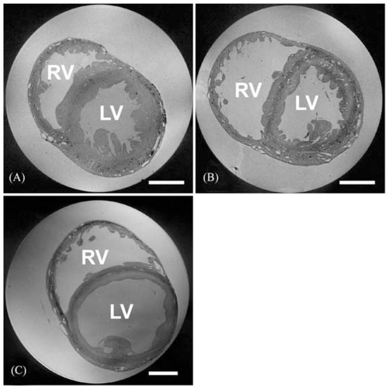
MR image planes obtained from contractured (A), slack (B), and volume-loaded (C) hearts (scale bar: 5 mm). In (A) and (B), voxel size is 26.5 × 26.5 × 24.5 μm, and in (C) 32 × 32 × 44 μm (a larger bore NMR tube was required for the volume-loaded heart). RV: right ventricle; LV: left ventricle. A full movie of the data in Figure 3B, progressing through transversal MRI sections from aorta to apex, can be downloaded from: http://mef.physiol.ox.ac.uk/MRI/Aorta_to_apex.avi.
FIGURE 4.

Longitudinal section of the data set in Figure 3B, reconstructed from multiple transverse 2D MR images showing structural detail such as aortic (AO) and right atrioventricular (AV) valves, free-running Purkinje network (PN), and ventricular cleavage planes (CP). LV: left ventricle, RA: right atrium.
Image Alignment
Histological techniques are superior to MRI in spatial resolution and discrimination of cell types, but they are limited by their destructive nature. Thus, tissue slice alignment is lost during mounting and 2D imaging. In addition, histological images are flawed by artifacts from nonlinear deformations, caused by tissue shrinkage during processing, by mechanical forces during microtome slicing, and by potentially inhomogeneous relaxation of sections before mounting. These drawbacks may be overcome by guiding image alignment using anatomical MRI data obtained from the same preparation prior to sectioning.
Several deformable registration algorithms have been developed to correct distortion in histological images,42–46 where distortion is compensated for by calculating the deformation that minimizes the difference between two adjacent slices. This may cause loss of real (or gain of artificial) structural data points.
In our approach, alignment is carried out in two steps. An initial coarse alignment step aims to minimize the difference between adjacent slices by applying rigid transformations only; that is, translation and rotation to ensure a good starting point for the subsequent registration procedure (Fig. 5B, D). In a second step, a partial differential equation-based approach is applied for mapping corresponding points between adjacent slices (Fig. 5C, E).45 In this approach, pixel trajectories between adjacent slices are computed based on a variational formulation in which departure from rigidity in an optical flow is penalized. The approach is “generalized rigid” in the sense that a rigid registration, indeed an interpolation, is obtained when one matches the given data. Otherwise, the registration is more elastic depending upon the strength of regularization. Furthermore, such regularization provides a true measure of elastic energy in relation to the more common linear elastic potential energy of displacements.45 The associated variational problem is solved by a pyramidal and geometric multigrid scheme.47
FIGURE 5.
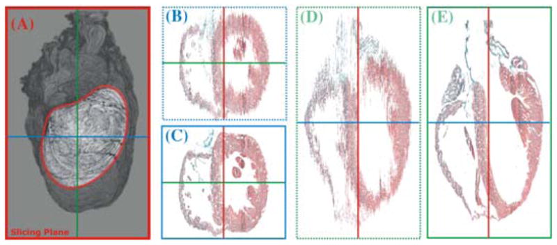
Three-dimensional reconstruction of a rabbit heart from serial histological sections that were performed approximately along the mediolateral axis of the heart (i.e., roughly parallel to the ventricular septum, see outline in (A). Slices were registered using an elastic registration with maximum rigidity, and results are visualized in two planes that are perpendicular to the original slicing plane, before (B and D) and after (C and E) registration. (See online version for color image.)
Results in Figure. 5 show the improvement achieved with these two transformations of the histological data sets. However, in the process of correcting geometrical distortion, valuable anatomical information arising from differences between adjacent slices may be lost, potentially compromising the accuracy of models generated. To overcome this drawback, we are working toward the addition of gross anatomical information from MR images to ensure that the slices are not overaligned in the deformation correction process.
Data Extraction
Segmentation
Using histological data, it is straightforward to discriminate different tissue types and the extracellular space. Most importantly, myocardial tissue, which underlies key electromechanical functioning of the heart, can be segmented automatically from Trichrome-stained sections using color thresholding.
Segmentation of the MRI stack is computationally more expensive and requires several processing steps. Typically, due to inevitable spatial variations in coil sensitivity, segmentation cannot be achieved simply by gray-level thresholding since in areas of decreased coil sensitivity an overlap in gray levels between object and background may occur. To circumvent this problem, in the present study thresholding was combined with probe-specific background subtraction and a set of morphological operations to facilitate segmentation. Briefly, two tissue-free slices from the MRI stack, one below the apex and another one above the atria, were selected, interpolated over the stack volume containing the tissue, and subtracted from the MRI stack to remove background gray levels. Subsequently, the entire stack was segmented slice by slice, starting at the apex. In each slice, a gray-level thresholding step was implemented and a binary mask was created, which allowed elimination of all pixels outside the heart. The binary mask was further improved by a set of morphological operations, including hole filling, and closing and removal of connected objects that are of a size below a certain (user-defined) number of voxels. For each slice, the mask from the previous slice was taken into account to avoid abrupt variations, which could possibly occur along low-contrast regions of the heart. Finally, the mask was applied to the entire MRI stack to discriminate the heart’s volume, excluding surrounding volume and cavities. Within the heart volume, differences in gray levels were sufficient to allow a direct segmentation between tissue and extracellular cleft space or vessels.
Fiber Orientation
The predominant fiber orientation in 2D images can be determined via filtered magnitude and direction assessment of intensity gradients (Fig. 2B).48 For calculating the principal orientation in 3D gray-level data sets, we used the gradient structure tensor.49 To calculate the structure tensor, the gradient of the image was calculated at each voxel of the histological 3D data sets, previously corrected for deformation as explained above. The tensor product of the gradient vector with itself was calculated, providing a 3 × 3 matrix for each voxel. The structure tensor is the result of filtering the matrix components using a Gaussian kernel. For “beam-like” structures such as cardiac fibers with a clear spatial orientation, this direction corresponds to the matrix eigenvector of the smallest eigenvalue. User-defined adjustment of the variance of the Gaussian kernel allows focusing on structures of a desired size such as fibers in 3D image stacks.
Coronary Vasculature
The present high-resolution MR image stacks also provide unique spatial information on coronary vascular networks within individual whole hearts. Although no vessel-specific stain was applied during the tissue preparation, the global structure of the vasculature can be segmented from the myocardium, as illustrated in Figure 6. This is achieved by isolating the voxels within the myocardium, which have a gray-level intensity range similar to that of the background. Starting from the segmented image stack of the myocardium, generated as described above, an intensity-based connected region-growing technique was combined with nonlinear edge detecting filters to isolate and segment the vasculature, while reducing noise, down to radii of approximately 30 μm. Figure 6A, B show horizontal and frontal views and rendering of the segmented vasculature produced via this process.
FIGURE 6.

Results of vascular segmentation from the data set shown in Figure 3B. (A) Inverted maximum intensity projection. (B) Volume rendering of segmented voxels representing the coronary tree. (C and D) Gray-level coded vessel radius distribution of coronary vasculature from 340 μm (dark) to 30 μm (light). (A and C) horizontal projections; (B and D) lateral projections.
The reconstruction of the vascular network into a model description was conducted by reducing the voxel-based graphical elements of the images to a skeletal structure and associating specific radii with each location along this structure (Fig. 6C, D). The local vessel radius is estimated from lumen boundaries identified by active contours, which supports resolution of irregularly shaped cross-sections. Once all vessel segments are tracked, they are assembled into networks. This compact model description can then be used to characterize the coronary structure and to serve as a mesh for numerical simulations of hemodynamic function.
Mesh Generation
To assemble models of cardiac structure and function, computational meshes have to be extracted from the generated data. These meshes will be used to calculate the origin and spread of electrical signals in the heart, compute active and passive deformation of myocardium, assess coronary flow and, ultimately, combine electrical and mechanical activity in the heart with fluid dynamics and valve movements. With such a broad range of applications in mind, mesh generation needs to address a wide range of demands in terms of accuracy, resolution, and implementation.
The simplest approach to mesh generation uses hexahedral finite elements to discretize domains on a regular structured grid. In this case, meshes can be generated efficiently from segmented image stacks, where each voxel is treated either as a myocardial element or a nonmyocardial element.
Generation of unstructured grids is a more complex operation, but offers several advantages over structured grids such as: (i) unstructured grids are better suited for defibrillation studies as they lack jagged boundaries that are typical for structured grids (which introduce spurious currents due to tip effects) and (ii) unstructured grids can be generated adaptively such that the spatial resolution varies (using a fine mesh with little adaptivity to model the myocardium and representing other tissue by coarser elements that grow in size with distance from myocardial surfaces).
An example of this approach is shown in Figure 7, where a mesh for calculating action potential propagation is extracted from the segmented data (Fig. 7A). We considered three different mesh generation approaches (Octree, Delaunay, and Advancing Front Techniques),50 and eventually applied an Octree-based meshing technique to produce boundary-fitted, locally refined, and conformal multielement meshes (Fig. 7B) that included microheterogeneities (Fig. 7C). The actual solution to the electrical problem is illustrated in Figure 7D.
FIGURE 7.
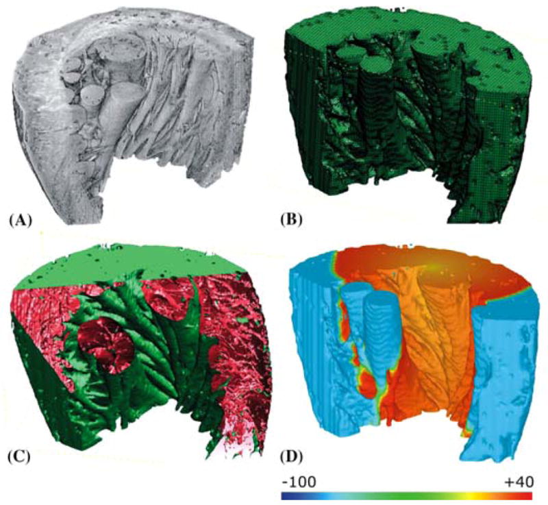
Left-ventricular wedge with papillaries and trabeculae. (A) 3D visualization of segmented tissue sub-stack. (B) adaptive FEM mesh. (C) partially cut wedge exposing histology-based microstructural detail. (D) bidomain simulation of effects of fiber direction on electrical impulse propagation. Scale bar illustrates voltage distribution in mV. (See online version for color figure.)
CHALLENGES
As outlined in the “Introduction,” the long-term objective of the proposed approach is to build individualized whole-heart reconstructions of cardiac structure and function, which are based on noninvasive imaging, enriched with histological data, and used for computational modeling of individual pathophysiological behavior and prediction of responses to experimental or clinical interventions.
This vision crucially hinges on automated construction of histoanatomically detailed computational meshes to support quantitative assessment of individual cardiac 3D structure and function. This requires advanced techniques for mesh generation, which will be aided by atlases and computationally efficient techniques for visualization and modeling to reintegrate the vast data sets involved in describing an individual heart. A schematic summary of this process is presented in Figure 8, illustrating the workflow from MRI- and histology-based segmentation, to registration of histological sections, coregistration of data sets, and finite element mesh generation.
FIGURE 8.

Generation of individualized high-resolution computational meshes from combined MRI and histological image data. Segmentation of MRI data results in a contiguous 3D data set. Segmented histological images have to be registered, slice by slice, and transformed to create a 3D histological stack. Both 3D data sets are then fused together. Such a histoanatomical global data set will enable the detailed segmentation of myocardial fibers, interstitial clefts, vessels, and connective tissue. In the process of segmentation, each voxel is classified and indexed (for instance 0 = myocardium, 1 = connective tissue, 2 = vessel, etc.), to account for the different properties of cells and regions that comprise the computational mesh. On this basis, provided the registration of histological data is sufficiently accurate, fiber orientation can be computed even without resorting to DTMRI.
Coregistration will make use of probabilistic atlases, an approach that is successfully used in clinical brain imaging, to complement the limited noninvasively obtained information about any individual patient with more detailed knowledge about generic histoanatomical features.51 This approach is emerging in the field of cardiac MRI,52 where template geometries have been successfully used for predictive computational modeling of cardiac anatomy.27 However, there is a lack of detailed whole-heart histoanatomical data sets to be integrated with these MRI templates; this deficiency is being addressed as described above.
Further challenges include the efficient integration of individual processing steps, suitable user-interfacing, and visualization of the various processing steps and corresponding data levels involved in the generation of individualized 3D representations of the heart.
On the applications side, linking cardiac histoanatomy to electromechanical function represents a major challenge as spatiotemporal heterogeneities in cell properties, coupling, or activation timing are not self-evident from cardiac structure information. Clearly, this is an area where further experimental species-defined research into cardiac electromechanics needs to be interrelated to structural insight to inform model development. This is particularly important for the modeling of pathologically disturbed behavior, which often involves complex structure–function remodeling.
More imminent progress will arise from the successful segmentation and tracking of anatomically based structures such as the Purkinje network or of the individual coronary trees. Thus, knowledge of exit and entry locations of free-running conduction pathways will guide the assignment of tissue properties relevant for simulation of proper sinus node activation patterns of the heart. Vascular structure–function relationships will benefit from the first direct calculation of branch angles and quantification of the relationship between microstructural fiber sheet arrangement and vessel orientation as well as from solving Navier–Stokes53 and finite deformation equations54 for functional simulation of the spatiotemporal distribution of coronary flow during the cardiac cycle.
It is evident from this short (and necessarily incomplete) list of challenges that constructing individual 3D histoanatomically detailed hearts requires a wide range of skills and expertise, and is highly collaborative in nature. Projects like this require a suitable backbone structure for curation of a wide variety of data commodities (such as images, executables, spreadsheets, or text) and tools for exchange. Furthermore, computational speed and short processing time are essential aspects of this process since the clinical utility of integrated individual 3D heart modeling crucially depends on its ability to provide results in time frames that are suitable to support data visualization, interpretation, diagnosis, and potentially, prediction of interventions. As a first step in using a broader computational base, the present project made extensive use of the integrative biology infrastructure set up at Oxford (which is open to interested users in the scientific community);55 other infrastructures will likely become available as progress is made toward the vision outlined in this article.
The authors would like to view the present article as the first step of a long journey. Much remains to be learned along the way to a truly exciting destination.
Acknowledgments
We thank Dr. Judith Sheldon and Barry Martin at Oxford Brookes University for expert histological advice, and Professor Kieran Clarke at Oxford University for access to the MR system of her laboratory. Individual facets of this collaborative study were supported by the UK Biotechnology and Biological Sciences Research Council (PK), UK Medical Research Council (RABB), the Austrian Science Fund (GP), the British Heart Foundation (JES; PK), the Royal Society of New Zealand (JL, NPS), and the U.S. National Institutes of Health (NPS; NT [HL63195]). The project is part of the Integrative Biology Initiative at Oxford University: http://www.integrativebiology.ox.ac.uk/.
References
- 1.Katz AM, Katz PB. Homogeneity out of heterogeneity. Circulation. 1989;79:712–717. doi: 10.1161/01.cir.79.3.712. [DOI] [PubMed] [Google Scholar]
- 2.Kohl P. Cardiac cellular heterogeneity and remodelling. Cardiovasc Res. 2004;64:195–197. doi: 10.1016/j.cardiores.2004.08.011. [DOI] [PubMed] [Google Scholar]
- 3.Kohl P. Heterogeneous cell coupling in the heart. Circ Res. 2003;93:381–383. doi: 10.1161/01.RES.0000091364.90121.0C. [DOI] [PubMed] [Google Scholar]
- 4.Camelliti P, Green CR, LeGrice I, Kohl P. Fibroblast network in rabbit sino-atrial node: structural and functional identification of homo- and heterologous cell coupling. Circ Res. 2004;94:828–835. doi: 10.1161/01.RES.0000122382.19400.14. [DOI] [PubMed] [Google Scholar]
- 5.Kohl P, Hunter P, Noble D. Stretch-induced changes in heart rate and rhythm: clinical observations, experiments and mathematical models. Prog Biophys Mol Biol. 1999;71:91–138. doi: 10.1016/s0079-6107(98)00038-8. [DOI] [PubMed] [Google Scholar]
- 6.Helm PA, Yournes L, Beg MF, et al. Evidence of structural remodeling in the dyssynchronous failing heart. Circ Res. 2006;98:125–132. doi: 10.1161/01.RES.0000199396.30688.eb. [DOI] [PubMed] [Google Scholar]
- 7.MacCallum JB. On the muscular architecture and growth of the ventricles of the heart. Johns Hopkins Hosp Rep. 1900;9:307–335. [Google Scholar]
- 8.Mall FP. On the muscular architecture of the ventricles of the human heart. Am J Anat. 1911;11:211–266. [Google Scholar]
- 9.Buckberg GD. New technology and old responsibilities. Euro J Cardiothorac Surg. 2005;27:472–474. doi: 10.1016/j.ejcts.2004.12.020. [DOI] [PubMed] [Google Scholar]
- 10.Schmid P, Jaermann T, Boesiger P, et al. Ventricular myocardial architecture as visualized in postmortem swine hearts using magnetic resonance diffusion tensor imaging. Euro J Cardiothorac Surg. 2005;27:468–474. doi: 10.1016/j.ejcts.2004.11.036. [DOI] [PubMed] [Google Scholar]
- 11.Kanai A, Salama G. Optical mapping reveals that repolarization spreads anisotropically and is guided by fiber orientation in guinea pig hearts. Circ Res. 1995;77:784–802. doi: 10.1161/01.res.77.4.784. [DOI] [PubMed] [Google Scholar]
- 12.Vetter FJ, Simons SB, Mironov S, et al. Epicardial fiber organization in swine right ventricle and its impact on propagation. Circ Res. 2005;96:244–251. doi: 10.1161/01.RES.0000153979.71859.e7. [DOI] [PubMed] [Google Scholar]
- 13.Chen PS, Cha YM, Peters BB, Chen LS. Effects of myocardial fiber orientation on the electrical induction of ventricular fibrillation. Am J Physiol. 1993;264:H1760–H1773. doi: 10.1152/ajpheart.1993.264.6.H1760. [DOI] [PubMed] [Google Scholar]
- 14.De Bakker JM, Stein M, van Rijen HV. Three-dimensional anatomic structure as substrate for ventricular tachycardia/ventricular fibrillation. Heart Rhythm. 2005;2:777–779. doi: 10.1016/j.hrthm.2005.03.022. [DOI] [PubMed] [Google Scholar]
- 15.Eason J, Schmidt J, Dabasinskas A, et al. Influence of anisotropy on local and global measures of potential gradient in computer models of defibrillation. Ann Biomed Eng. 1998;26:840–849. doi: 10.1114/1.68. [DOI] [PubMed] [Google Scholar]
- 16.Hooks DA, Tomlinson KA, Marsden SG, et al. Cardiac microstructure: implications for electrical propagation and defibrillation in the heart. Circ Res. 2002;91:331–338. doi: 10.1161/01.res.0000031957.70034.89. [DOI] [PubMed] [Google Scholar]
- 17.Waldman LK, Nosan D, Villarreal F, Covell JW. Relation between transmural deformation and local myofiber direction in canine left ventricle. Circ Res. 1988;63:550–562. doi: 10.1161/01.res.63.3.550. [DOI] [PubMed] [Google Scholar]
- 18.Chen J, Liu W, Zhang H, et al. Regional ventricular wall thickening reflects changes in cardiac fiber and sheet structure during contraction: quantification with diffusion tensor MRI. Am J Physiol. 2005;289:H1898–H1907. doi: 10.1152/ajpheart.00041.2005. [DOI] [PubMed] [Google Scholar]
- 19.Delhaas T, Arts T, Bovendeerd PH, et al. Subepicardial fiber strain and stress as related to left ventricular pressure and volume. Am J Physiol. 1993;264:H1548–H1559. doi: 10.1152/ajpheart.1993.264.5.H1548. [DOI] [PubMed] [Google Scholar]
- 20.Mazhari R, Omens JH, Covell JW, McCulloch AD. Structural basis of regional dysfunction in acutely ischemic myocardium. Cardiovasc Res. 2000;47:284–293. doi: 10.1016/s0008-6363(00)00089-4. [DOI] [PubMed] [Google Scholar]
- 21.Tseng WY, Dou J, Reese TG, Wedeen VJ. Imaging myocardial fiber disarray and intramural strain hypokinesis in hypertrophic cardiomyopathy with MRI. J Magn Reson Imag. 2006;23:1–8. doi: 10.1002/jmri.20473. [DOI] [PubMed] [Google Scholar]
- 22.Helm P, Beg MF, Miller MI, Winslow RL. Measuring and mapping cardiac fiber and laminar architecture using diffusion tensor imaging. Ann N Y Acad Sci. 2005;1047:296–307. doi: 10.1196/annals.1341.026. [DOI] [PubMed] [Google Scholar]
- 23.Ablitt NA, Gao J, Keegan J, et al. Predictive cardiac motion modeling and correction with partial least squares regression. IEEE Transac Med Imag. 2004;23:1315–1324. doi: 10.1109/TMI.2004.834622. [DOI] [PubMed] [Google Scholar]
- 24.Larson AC, Kellman P, Arai A, et al. Preliminary investigation of respiratory self-gating for free-breathing segmented cine MRI. Magn Resonan Med. 2005;53:159–168. doi: 10.1002/mrm.20331. [DOI] [PMC free article] [PubMed] [Google Scholar]
- 25.Lotjonen J, Pollari M, Kivisto S, Lauerma K. Correction of motion artifacts from cardiac cine magnetic resonance images. Acad Radiol. 2005;12:1273–1284. doi: 10.1016/j.acra.2005.07.002. [DOI] [PubMed] [Google Scholar]
- 26.Scollan DF, Holmes A, Winslow RL, Forder J. Histological validation of myocardial microstructure obtained from diffusion tensor magnetic resonance imaging. Am J Physiol. 1998;275:H2308–H2318. doi: 10.1152/ajpheart.1998.275.6.H2308. [DOI] [PubMed] [Google Scholar]
- 27.Beg MF, Helm PA, McVeigh E, et al. Computational cardiac anatomy using MRI. Magn Resonan Med. 2004;52:1167–1174. doi: 10.1002/mrm.20255. [DOI] [PMC free article] [PubMed] [Google Scholar]
- 28.Miquel ME, Hill DLG, Baker EJ, et al. Three- and four-dimensional reconstruction of intra-cardiac anatomy from two-dimensional magnetic resonance images. Intl J Cardiovasc Imag. 2003;19:239–254. doi: 10.1023/a:1023671031207. [DOI] [PubMed] [Google Scholar]
- 29.Angelie E, de Koning PJ, Danilouchkine MG, et al. Optimizing the automatic segmentation of the left ventricle in magnetic resonance imaging. Med Phys. 2005;32:369–375. doi: 10.1118/1.1842912. [DOI] [PubMed] [Google Scholar]
- 30.Pluempitiwiriyawej C, Moura JM, Wu YJ, Ho C. STACS: new active contour scheme for cardiac MR image segmentation. IEEE Transac Med Imag. 2005;24:593–603. doi: 10.1109/TMI.2005.843740. [DOI] [PubMed] [Google Scholar]
- 31.Holmes AA, Scollan DF, Winslow RL. Direct histological validation of diffusion tensor MRI in formaldehyde-fixed myocardium. Magn Resonan Med. 2000;44:157–161. doi: 10.1002/1522-2594(200007)44:1<157::aid-mrm22>3.0.co;2-f. [DOI] [PubMed] [Google Scholar]
- 32.Cumming G, Henderson R, Horsfield K, Singhal S. The Pulmonary Circulation and Interstitial Space. University of Chicago Press; Chicago: 1969. The functional morphology of the pulmonary circulation; pp. 327–338. [Google Scholar]
- 33.VanBavel E, Spaan J. Branching patterns in the porcine coronary arterial tree. Circ Res. 1992;71:1200–1212. doi: 10.1161/01.res.71.5.1200. [DOI] [PubMed] [Google Scholar]
- 34.Kassab GS. The coronary vasculature and its reconstruction. Ann Biomed Eng. 2000;28:903–915. doi: 10.1114/1.1308494. [DOI] [PubMed] [Google Scholar]
- 35.Kassab GS, Rider CA, Tang NJ, Fung YC. Morphometry of pig coronary arterial trees. Am J Physiol. 1993;265:H350–H365. doi: 10.1152/ajpheart.1993.265.1.H350. [DOI] [PubMed] [Google Scholar]
- 36.Dhawan S, Dharmashankar KC, Tak T. Role of magnetic resonance imaging in visualizing coronary arteries. Clin Med Res. 2004;2:173–179. doi: 10.3121/cmr.2.3.173. [DOI] [PMC free article] [PubMed] [Google Scholar]
- 37.Nordsletten DA, Blackett S, Bentley MD, et al. Structural morphology of renal vasculature. Am J Physiol. 2006;291:H296–H309. doi: 10.1152/ajpheart.00814.2005. [DOI] [PubMed] [Google Scholar]
- 38.Karnovsky MJ. A formaldehyde-glutaraldehyde fixative of high osmolarity for use in electron microscopy. J Cell Biol. 1965;27:137A–138A. [Google Scholar]
- 39.Schneider JE, Bamforth SD, Farthing CR, et al. Rapid identification and 3D reconstruction of complex cardiac malformations in transgenic mouse embryos using fast gradient echo sequence magnetic resonance imaging. J Mol Cell Cardiol. 2003;35:217–222. doi: 10.1016/s0022-2828(02)00291-2. [DOI] [PubMed] [Google Scholar]
- 40.Schneider JE, Bamforth SD, Grieve SM, et al. High-resolution, high-throughput magnetic resonance imaging of mouse embryonic anatomy using a fast gradient-echo sequence. Magma. 2003;16:43–51. doi: 10.1007/s10334-003-0002-z. [DOI] [PubMed] [Google Scholar]
- 41.Schneider JE, Bose J, Bamforth SD, et al. Identification of cardiac malformations in mice lacking PTDSR using a novel high-throughput magnetic resonance imaging technique. Biomed Central Develop Biol. 2004;4:16. doi: 10.1186/1471-213X-4-16. [DOI] [PMC free article] [PubMed] [Google Scholar]
- 42.Sorzano CO, Thevenaz P, Unser M. Elastic registration of biological images using vector-spline regularization. IEEE Transac Biomed Eng. 2005;52:652–663. doi: 10.1109/TBME.2005.844030. [DOI] [PubMed] [Google Scholar]
- 43.Makela T, Clarysse P, Sipila O, et al. A review of cardiac image registration methods. IEEE Transac Med Imag. 2002;21:1011–1021. doi: 10.1109/TMI.2002.804441. [DOI] [PubMed] [Google Scholar]
- 44.Wirtz S, Papenberg N, Fischer B, Schmitt O. Robust and staining-invariant elastic registration of a series of images from histologic slices. Medical imaging 2005: physiology, function, and structure from Medical Images. 2005:1256–1262. [Google Scholar]
- 45.Keeling S, Ring W. Medical image registration and interpolation by optical flow with maximal rigidity. J Math Imag Vision. 2005;23:47–65. [Google Scholar]
- 46.Pitiot A, Bardinet E, Thompson PM, Malandain G. Piecewise affine registration of biological images for volume reconstruction. Med Image Anal. 2006;10(3):465–483. doi: 10.1016/j.media.2005.03.008. [DOI] [PubMed] [Google Scholar]
- 47.Keeling SL. Geometric multigrid for generalized affine and generalized rigid image registration. J Math Imag Vision. 2006 In press. [Google Scholar]
- 48.Karlon W, Covell JW, McCulloch AD, Omens JH. Automated measurement of myofiber disarray in transgenic mice with ventricular expression of Ras. Anat Rec. 1998;252:612–625. doi: 10.1002/(SICI)1097-0185(199812)252:4<612::AID-AR12>3.0.CO;2-1. [DOI] [PubMed] [Google Scholar]
- 49.Weickert J. Coherence-enhancing diffusion filtering. Intl J Comp Vision. 1999;31:111–127. [Google Scholar]
- 50.Owen S. A survey of unstructured mesh generation technology. 2004 http://www.andrew.cmu.edu/user/sowen/survey/index.html.
- 51.Thompson PM, Mega MS, Narr KL, et al. Brain image analysis and atlas construction. In: Fitzpatrick M, Sonka TM, editors. SPIE Handbook of Medical Image, Processing and Analysis. SPIE Press; 2000. In press. [Google Scholar]
- 52.Lorenzo-Valdes M, Sanchez-Ortiz GI, Elkington AG, et al. Segmentation of 4D cardiac MR images using a probabilistic atlas and the EM algorithm. Med Image Anal. 2004;8:255–265. doi: 10.1016/j.media.2004.06.005. [DOI] [PubMed] [Google Scholar]
- 53.Smith NP, Pullan AJ, Hunter PJ. An anatomically based model of coronary blood flow and myocardial mechanics. SIAM J App Math. 2002;62:990–1018. [Google Scholar]
- 54.Nash MP, Hunter PJ. Computational mechanics of the heart. J Elast. 2000;61:121–141. [Google Scholar]
- 55.Pitt-Francis J, Garny A, Gavaghan D. Enabling computer models of the heart for high-performance computers and the grid. Phil Transac Roy Soc. 2006;364:1501–1516. doi: 10.1098/rsta.2006.1783. [DOI] [PubMed] [Google Scholar]