

Abstract
There is increasing interest in fabricating shape-specific polymeric nano and microparticles for efficient delivery of drugs and imaging agents. The size and shape of these particles could significantly influence their transport properties and play an important role in in vivo biodistribution, targeting and cellular uptake. Nanoimprint lithography methods, such as Jet-and-flash imprint lithography (J-FIL), provide versatile top-down processes to fabricate shape-specific, biocompatible nanoscale hydrogels that can deliver therapeutic and diagnostic molecules in response to disease-specific cues. However, the key challenges in top-down fabrication of such nanocarriers are scalable imprinting with biological and biocompatible materials, ease of particle-surface modification using both aqueous and organic chemistry as well as simple yet biocompatible harvesting. Here we report that a biopolymer-based sacrificial release layer in combination with improved nanocarrier-material formulation can address these challenges. The sacrificial layer improves scalability and ease of imprint-surface modification due to its switchable solubility through simple ion exchange between monovalent and divalent cations. This process enables large-scale bio-nanoimprinting and efficient, one-step harvesting of hydrogel nanoparticles in both water- and organic-based imprint solutions.
Keywords: Nanoimprinting, Release Layer, Poly (Acrylic Acid), Drug delivery, Switchable water solubility, shape specific nanoparticles
In recent years, nanoparticles have been widely investigated for delivering various biomolecules and drugs for both diagnostic and therapeutic purposes.1–5 Due to their small size, nanoparticles could deliver drugs and imaging agents intracellularly and also penetrate through the narrow gaps between the endothelial cells of blood vessels at tumor sites (Enhanced Permeation and Retention, (EPR) effect), thereby allowing efficient, tumor-targeted delivery.6 It has been previously shown that particle size is critical for successful delivery of drugs to cells both in vitro as well as in vivo.7–9 Recently, the effect of shape has also been found to play a major role.10–16 Most natural structures including red blood cells, viruses and bacteria that circulate and infect human body are non-spherical. This motivates a study of the effect of particle geometry in cellular uptake, biodistribution and retention of nanoparticles in the body. Theoretical studies have predicted that both size and shape could play an important role on particle margination dynamics in blood vessels.13 Geng et al. showed that filomicelles (cylindrically shaped micelles) up to 20 μm long and 50 nm in diameter were able to persist in circulation for more than a week while nanoscale spherical particles were eliminated quickly.11 Champion et al. showed that internalization of microparticles by macrophages was dependent on local shape of the particles.17 Elliptical particles attached to macrophages at the pointed end were shown to be internalized in minutes while the particles attached at the flat surface took over 12 hours for complete internalization. Despite these advances in synthesizing nanoscale and biocompatible carriers, one major drawback of these existing methods is the scale-up capability of nanoparticle production. In order to systematically study the effect of nanoscale geometry on cellular uptake, in vivo biodistribution and drug delivery, it is critical to develop high-throughput fabrication methods that allow large-scale production of nanoparticles.
Although a number of works have shown successful fabrication of soft polymeric particles of different shapes, only a few methods have been reported that succeed in fabricating shape and size specific, sub-200 nm particles.10, 18–22 Such particles are required to effectively reach tumor sites through the EPR effect by passing through leaky endothelial fenestrations as well as for efficient uptake by non-phagocytic target cells.23 The fabrication processes generally involves stamping out (imprinting) polymeric particles using a mold to give the required shape and size. After the nanoparticles are formed, they need to be removed from the imprint substrate (harvesting) into a bio-compatible liquid. Gratton et al. reported physically scraping of the particles from the substrate by moving an acetone drop over the molded pattern with a glass slide.10 Such a physical process may damage and alter the shape of the soft polymeric particles and could be difficult to scale up. Enlow et al. described a modified particle harvesting process by attaching the molded pattern with an excipient layer and reheating the assembly, thereby causing the polymeric particles to melt at the contact and transfer to the excipient layer which can then be dissolved to harvest particles.24 Merkel et al. also reported an improved method to harvest particles from molded patterns by placing the mold over 0.1% Poly (Vinyl Alcohol) (PVA) solution in water and then cooling the assembly in a −80°C cooler causing the particles to get trapped in the resulting ice layer. The mold is then peeled away leaving the particles embedded in ice.25 In a different work, Buyukserin et al. have used Poly (Methyl Methacrylate) (PMMA) as a sacrificial layer that was later dissolved using acetone to harvest SU-8 (an epoxy based photoresist) particles.19 However, exposure of biological drugs and polymeric drug carriers to acetone and other non-biocompatible chemicals are a cause of concern in drug delivery applications. To address these issues, Glangchai et al. reported a nanoimprint lithography process that used a water-soluble PVA release layer for fabricating sub-100 nm, shape-specific hydrogel particles.20–21 Although this process was completely water based, dispensing of the water-based imprint solution of Poly (Ethylene Glycol Di-acrylate) (PEGDA) can result in local dissolution of the water-soluble PVA sacrificial layer, resulting in low adhesion force between the sacrificial layer (PVA) and the cured resist (PEGDA). This causes peel off of the cured resist onto the template resulting in template contamination and hence preventing continuous, large-scale imprinting. In addition, higher molecular weight PEGDA (700 Da) used in these earlier studies was more viscous and required dispensing at higher volumes to ensure uniform spreading and resulting in thicker residual layers (thus needing a longer etching step) as well as limited shape retention when imprinting vertical, high-aspect ratio, sub-100 nm particles.
Previously, Linder et al. reported that Poly (Acrylic Acid) (PAA) can be used as a water soluble sacrificial layer in surface micromachining.26 The group also showed that solubility of thin layers of PAA can be chemically controlled by varying the ion concentration. Here, we report a large-scale imprinting (whole wafer scale imprinting yielding approximately 2.5×10¹¹ particles of 100nm diameter and 80nm height per 8 inch silicon wafer) and particle-harvesting method based on a sacrificial PAA release layer with switchable water solubility i.e. the water solubility of the sacrificial layer changes depending on the presence of divalent cations. Specifically, the PAA layer becomes insoluble in water in the presence of Ca2+ ions, while removal of calcium “switches” it to a soluble layer. This allows for continuous imprinting and efficient, one-step aqueous-based release of nanoparticles. The PAA release layer is compatible with both aqueous and organic solvent-based imprinting. The use of this switchable sacrificial layer also enables us to readily modify imprinted particles in both aqueous and organic solvents prior to particle harvesting. In addition, sub-10 nm residual layer thickness was achieved through the use of a low molecular weight, low viscosity PEGDA. This also resulted in improved shape replication of imprinted particles. This versatile, switchable layer-based imprinting provides a robust method for large-scale fabrication of shape-specific nanoparticles, both for fundamental studies on shape-effects for nanoscale particle transport as well as for applied studies on the effects of particle geometry on drug and contrast agent delivery.
Results and discussion
Imprint with a PVA Release Layer
We first examined the imprint results with the use of a PVA release layer. Imprint of water-based PEGDA solution on PVA was found to be initially uniform. However, the quality of imprints deteriorated during scale up with increasing number of imprints. Figure 1(a) shows a zoomed out scanning electron microscopy (SEM) image of the third PEGDA imprints on a PVA release layer with the use of water-based imprint solution. Both the SEM and the fluorescence images in figures 1(b) and (c) show non-uniform surface features. The high-resolution SEM images of Figs. 1(d), (e) and (f) further reveal that some areas of the imprints were peeled off from the substrate, deformed or folded. When Di-Methyl Sulfo-Oxide (DMSO) based imprint solution was used, even the first imprint was not uniform due to fast dissolution of PVA in DMSO (data not shown).
Figure 1.

Representative SEM and Fluorescence Microscopy images of PEG imprints on a PVA release layer with the use of a water-based imprint solution. a) SEM image of imprint at low magnification, b) and, c) Fluorescence microscopy images of the imprint region at excitation wavelength of 488 nm and emission at 520 nm. d), e), f) - Zoomed in SEM images of the imprints highlighting different regions of defective and good imprints.
It is known that wetting and adhesion of the imprint solution on the substrate and template surfaces influence imprint quality. Template filling by the imprint solution depends on the contact angles of the imprint solution on the substrate and the template surfaces.27–28 If the template surface is made highly non-wetting to improve release performance, it will cause partial filling of the features on the template and poor imprint pattern fidelity.28 Moreover, adhesion between the imprint solution and the underlying release layer needs to be greater than the adhesion between the imprint solution and the template surface. When PVA is used as the underlying release layer, the PEGDA imprint solution adheres to the PVA surface due to weak H-bonds and physical entanglement of the polymeric PEGDA chains into the PVA surface. This bonding is not adequate for imprinting a densely packed nano-feature pattern that leads to large contact area between the imprint solution and the template surface. Moreover, the water or DMSO based solvent in the imprint solution may dissolve the underlying PVA layer, further weakening the adhesion between the sacrificial PVA layer and the cured resist, thereby causing peel-off of the UV-cured imprint pattern from the substrate and onto the template.
The results found with the PVA release layer suggested the need of an alternative release layer material that could be water soluble to allow particle harvesting using simple, one-step aqueous processes, and yet is insoluble in water-based imprinting solutions to avoid local dissolution and template contamination. Besides this apparently conflicting requirement, it is desirable that the release layer materials can be spun coated uniformly on the substrate so that nanoscale features can be reproducibly imprinted on the release layer. Moreover, the release layer needs to yield high adhesion strength and low contact angle with the imprint solution to avoid peel off during molding and complete filling of the template.
Imprint with a PAA Release Layer
Poly (Acrylic Acid) (PAA) is insoluble in many organic solvents such as DMSO. Moreover, the acryl functional groups in PAA promote covalent bonding between the PEGDA imprint and the surface of PAA, which is also non-toxic. Hence, we have explored PAA as an alternative release layer. When 2% w/v 60KDa PAA solution in water was spun at 3000 rpm on the silicon substrate, we were able to achieve a uniform PAA thickness of 20–30 nm on the substrate. Because PAA is not soluble in DMSO, we found that DMSO-based PEGDA solutions can be directly imprinted on a substrate coated with an untreated PAA release layer. The imprints were highly uniform and showed good template replication at sub 100 nm scale, as shown in Fig 2(a). SEM images show complete filling of template even to the edges. Fluorescence microscopy images of imprinted resist over PAA showed uniform fluorescence intensity, as shown in Fig 2(c). Furthermore, we have also successfully encapsulated a hydrophobic, anti-cancer drug doxorubicin in these nanoimprinted particles, as shown by fluorescence microscopy images of released nanoparticles (Fig 2(d)). Based on the starting concentration of Dox in the imprinting solution the theoretical maximum loading in these imprinted particles would be 41.66μg of Dox per gram of particles). In addition, we have shown that doxorubicin is present within these imprinted nanoparticles (55% PEGDA imprints in DMSO) even 72 hours after particle harvesting and release in water (Supplemental Figure S1). Dox release kinetics over a 72 hour period was also studied and showed a sustained release pattern (Supplemental Figure S2).
Figure 2.

Imprints over PAA using a DMSO based imprint solution (a) Cross-sectional SEM images of 100 nm diameter × 80 nm height cylindrical particles (b) Top SEM images of 800 nm × 100 nm × 100 nm cuboidal particles (c) Fluorescence images of FITC containing 120 nm diameter × 80 nm height cylindrical particles (d) Fluorescence images of Doxorubicin containing 350 nm diameter × 120 nm height cylindrical particles taken 2 hours after being released in water.
We found that the PAA layer allows successful automated 350 imprints of DMSO-based PEGDA with FITC encapsulation that covers an entire 8 inch wafer, as shown in Figure 3. This is a significant improvement over the previous process and does not represent the limit of the scalability of the process. In this study, we stopped imprinting at 350 imprints as it provided adequate evidence of the scalability of the process. The cross section SEM in Fig. 3(b) shows that the residual layer thickness (RLT) is as small as 9 nm. In comparison, the RLT achieved in the previous imprint process was 30–40 nm.29 Because the residual layer needs to be etched with oxygen plasma prior to particle harvesting, the reduced RLT helps to reduce wastage of expensive biomaterials during oxygen plasma etching. The RLT depends on the viscosity of the imprinting solution, crosslinking density of polymer chains, and aspect ratio of particles being formed. The reduced RLT was achieved here with the use of PEG-di-acrylate (PEGDA) with a lower molecular weight (MW: 200 and 400 Da) and lower viscosity, which in turn allowed a smaller drop dispensing volume (reduction by 50% compared to drops formed when using higher molecular weight (700Da). The lower molecular weight formulation also allows for better template replication and shape retention (data not shown) which, in conjunction with the PAA sacrificial layer, resulted in an improved and scalable nanoimprinting process.
Figure 3.

(a) Optical photograph of a wafer showing more than 350 successful automated repeatable imprints of a dense 5 mm × 5 mm template with 100-nm-diameter and 80-nm-height imprint features. (b) Cross-sectional SEM of 800 nm × 100 nm × 100 nm cuboids with sub 10 nm residual layer thickness
In this study, the imprint throughput was limited by the relatively small 5 mm × 5 mm imprint field on the template to 20 hours per wafer. This throughput can be potentially improved to less than 1 minute per wafer with the use of a large-area template and high-speed, high-resolution material jetting, as demonstrated for similar imprint processes for applications in light-emitting diodes (LEDs), magnetic storage and electronic devices.28
Because most therapeutic biomolecules are only active and stable under aqueous conditions, it is desirable to use water as the solvent for the imprint solution and the release layer. As mentioned above, the release layer used should not dissolve in the aqueous imprint solution but must dissolve in water-based harvesting solution after imprinting. Commercially available sodium salt of PAA rapidly solubilizes in water so it cannot be used directly as the release layer for water-based imprint solution. However, PAA is known to reversibly change its solubility in water depending on the concentration of monovalent and divalent ions.30 As shown in Fig. 4, in presence of Ca2+ ions, PAA ionically crosslinks to become water insoluble, and can be made water soluble after the Ca2+ ions are exchanged with Na+ ions. We performed an ion exchange process by treating the wafer coated with the PAA release layer with 0.5M CaCl2 solution. The wafer was then washed with de-ionized water leaving the PAA layer ionically crosslinked with Ca2+ ions. This procedure makes the PAA layer insoluble in water. We found that Ca2+ treated PAA allows successful automated imprinting of at least 30 successive imprints (data not shown).
Figure 4.
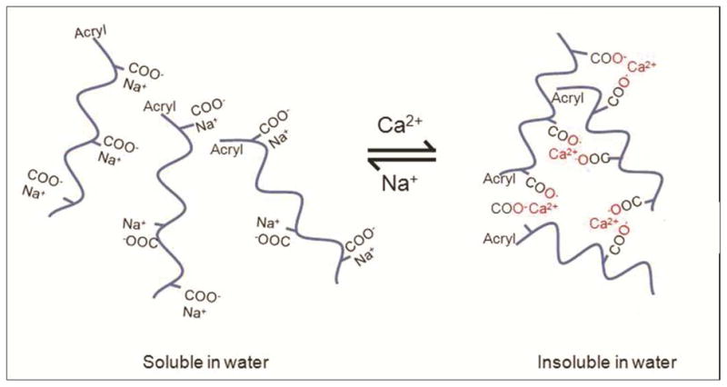
Reversible tuning of the solubility of PAA in water by exchanging between Ca2+ and Na+ ions.
As shown in Table 1, we have conducted contact angle measurements of various imprinting solutions on different sacrificial layers including PAA, Ca2+ treated PAA, and PVA, as well as on a fused silica template treated with a fluorinated self assembled layer (FSAM).28, 31–33 The contact angle was found to increase somewhat when the Ca2+ treated PAA release layer is used with the water- or DMSO- based imprint solutions, suggesting decreased wetting behavior. This however did not affect the template filling and there was adequate adhesion between the cured resist and the Ca2+ treated PAA surface as shown by successful imprinting and release of particles in figure 5.
Table 1.
Contact angle (in degrees) measurement results
| Solution | ||||
|---|---|---|---|---|
| Substrate | DI Water | 50% w/v PEGDA400 mw in Water | DMSO | 50% w/v PEGDA400 mw in DMSO |
| PVA | 20.0 ± 0.9 | 8.5 ± 0.3 | 10.8 ± 0.5 | 8.5 ± 0.4 |
| PAA | 7.0 ± 0.6 | 10.4 ± 1.2 | 10.9 ± 1.1 | 8.4 ± 1.0 |
| PAA Treated with Ca2+ | 8.3 ± 0.7 | 17.0 ± 0.7 | 35.7 ± 0.5 | 27.9 ± 0.5 |
| Fused Silica coated SAM | 7.4 ± 0.9 | 16.6 ± 0.6 | 7.6 ± 0.6 | 11.5 ± 0.3 |
Figure 5.

(a) SEM and (b) fluorescence microscopy images of 240 nm diameter and 125 nm height cylindrical, FITC-loaded particles imprinted over Ca2+ treated PAA layer using a water-based PEGDA resist. Imprints were released from the imprint substrate into water and subsequently drop casted on a different clean silicon wafer substrate for SEM imaging.
Furthermore, because the Ca2+ treated PAA layer is water insoluble, chemical functionalization of the imprinted nanoparticles can be carried out in a water-based environment before releasing the particles from the imprint substrate. As an example, Figure 6(a–b) shows that the as-imprinted particles can be washed in water multiple times without being released. This process is advantageous compared to functionalization of released particles as it avoids loss and distortion of particles caused by filtration and high speed centrifugation. After the PAA layer solubility is switched to be water soluble with the addition of monovalent ions (Na+), the fabricated nanoparticles can be harvested readily into water, as shown in Fig. 6(d).
Figure 6.
SEMs of (a) 120 nm diameter × 80 nm height cylindrical imprinted PEGDA particles in DMSO after imprinting and etching, (b) after incubation in 0.1M CaCl2 water solution for 5 minutes, (c) after washing twice with deionized water for 5 minutes each time, (d) after washing with 0.1M NaOH water solution
In vitro Cytotoxicity
Two types of particles (120nm diameter × 80nm height and 400nm × 100nm × 100nm cuboids) fabricated using this process were tested for cytotoxicity in HeLa cells using an MTS assay (after 4, 24 and 48 hours of incubation). Particles were found to be essentially non-toxic. For 120nm diameter × 80nm height particles administered at a dose of 105 particles per cell, cell viability was found to be 100.2 ± 6.4%, 99.3 ± 2.1 and 101.7 ± 5.2% after 4, 24 and 48 hours respectively. For 400nm × 100nm × 100nm cuboidal particles administered at a dose of 105 particles per cell, cell viability was found to be 98.9 ± 1.3%, 101.4 ± 6.2% and 103.6 ± 0.86% after 4, 24 and48 hours respectively.
Conclusion
These experiments show that PAA can be used as a highly versatile release layer for UV based nanoimprint lithography of biocompatible polymers. The water solubility of PAA is switchable by exchanging monovalent and divalent cations. This feature allows for large scale, repeatable, high-fidelity imprinting of nanoparticles and naostructures in both water- and organic solvent-based imprint solutions. In addition, this method allows aqueous environment-based surface-functionalization of imprinted particles directly on the imprint substrate as well as a simple method for particle release in water-based solutions. It offers advantage over other organic solvent-based sacrificial layers that may not be biocompatible because of the exposure of the particles to acetone, toluene, or other toxic solvents during the fabrication process. Moreover, with the use of a small-molecular weight PEGDA, the residual layer thickness was reduced to below 10 nm so as to minimize wastage of expensive biomaterials via oxygen plasma etching of the residual layer. In addition, successful encapsulation and release kinetics of model small molecule model drugs is demonstrated. These results represent important advancements toward high-throughput, biocompatible fabrication of drug nanocarriers and nanostructures using top-down nanoimprint lithography.
Methods
Materials and Reagents
Poly (Ethylene Glycol) diacrylate (PEGDA, Mw 200 and 400) was purchased from Sartomer, Exton, PA. The ultraviolet (UV) photoinitiator, 2-hydroxy-1-[4-(hydroxyethoxy) phenyl]-2-methyl-1 propanone (I2959) was purchased from Ciba, Basel, Switzerland. Fluorescein-o-acrylate monomer (97%), Poly (Vinyl Alcohol) (PVA, Mw 31 000) (Fluka), and dimethyl sulfoxide (DMSO) were purchased from Sigma Aldrich, St. Louis, MO. PAA Sodium salt, Mw 60 000 was purchased from Polysciences, Warrington, PA. Contact angle measurements were done using a Kruss - Drop Shape analysis System DSA 10 Mk2. Scanning Electron Microscopy (SEM) was done on a Zeiss Supra 40VP SEM model and fluorescence microscopy was done on a Zeiss Axiovert 200M.
Imprinting Solution
Two types (i.e. water and DMSO based) of imprinting solution were prepared. 50% w/v Poly Ethylene Glycol Di-acrylate (Mw: 400 Da) was mixed with de-ionized water or Poly Ethylene Glycol Di-acrylate (Mw: 200 Da) was mixed with DMSO and a 0.07% w/v final concentration I2959 as photoinitiator. To allow fluorescence microscopy, 2% fluorescein –o-Acrylate was dissolved in the water based solution with help of 15% v/v DMSO or upto 16% fluorescein –o-Acrylate for DMSO based solution.
Release Layer
A diluted 2% w/v PAA solution was prepared in water. About 5mL of this PAA solution was spincoated on an 8” Silicon wafer at 3000 rpm for 40 seconds and the wafer was then baked on a hot plate at 160°C for 1 minute. To make this layer suitable for water based imprinting, the wafer was submerged in a 0.5M CaCl2 solution in water for 5 minutes, washed with 50mM CaCl2 solution and finally washed with deionized water. The wafer was spun at 3000 rpm and baked again at 160°C for 1 minute to remove any remaining residual water.
Imprinting Parameters
Nanoimprinting was carried out using the J-FIL process on an Imprio 100, Molecular Imprints Inc., Austin, TX.29 In the J-FIL process, a pre-patterned transparent quartz template was pressed onto resist droplets inkjetted on silicon wafers pre-coated with PAA release layer, causing it to spread, and fill the features in the quartz mold. The resist was then exposed to UV light (at 365nm wavelength at 5 mW/cm2 intensity), for 25 seconds to photopolymerize the molded resist. The template was then removed revealing the desired nanostructures. The imprints were sputter coated with 3 nm of platinum layer to make them conductive and residual layer was measured using cross-sectional SEM. A low power (35 Watts) Argon plasma etch (Oxford Instruments Plasma Lab 80+) was performed at a pressure of 10 mTorr with Ar (20 sccm) and O2 (4 sccm) yielding an etch rate of 0.6nm/sec.
Release and Imaging of Nanoparticles
Imprints were washed twice with DMSO after etching on the wafer to remove any unreacted polymer. Imprints were submerged in DMSO, incubated for 5 minutes and blow dried with Nitrogen. To release the particles, 50μl of de-ionized water was added per 5mm×5mm imprint area and incubated for 1 minute to dissolve the underlying PAA layer. The water containing nanoparticles was dialyzed for 2 days using 20K MWCO Slide-A-Lyzer Mini Dialysis devices (Pierce Inc.).
For SEM, 3μl of nanoparticle suspension was dispensed on a SEM stub, air dried and sputter coated with 3nm of Platinum layer to make the sample conductive. For fluorescence microscopy, 3μl of nanoparticle suspension was dispensed on a glass slide and covered with a glass cover slip. Imaging was done at 100X magnification objective by exciting the sample using a 488nm wavelength laser.
In vitro Cytotoxicity
HeLa cells were used for in vitro cytotoxicity assay of the fabricated PEGDA nanocarriers using an MTS assay (CellTiter 96 AQueous One Solution Cell Proliferation Assay, Promega). 10,000 cells were plated overnight in a 96 well plate. Assays were performed by adding the MTS reagent solution to culture wells and recording the absorbance (at 490nm) at after particle incubation of 4, 24 and 48 hours. A ratio of 105 nanocarriers per cell was used. All the experiments were done in groups of 6.
Doxorubicin release kinetics
Imprinting resist was made with 55% PEGDA solution in DMSO containing 50μg/ml of Doxorubicin and imprinted on a PAA sacrificial layer to form cylindrical features with 350nm diameter and 120nm height. These cylindrical, doxorubicin containing nanoparticles were released in water and dialyzed over 72 hours using 20K MWCO Slide-A-Lyzer Mini Dialysis devices (Pierce Inc.). Fluorescence measurements of the particle solution were taken at different time intervals using a plate reader (Biotek, Synergy) and normalized against the initial reading to calculate percent drug released from the particles over time. Fluorescence microscopy images were also taken at different time intervals using a 100X magnification objective.
Supplementary Material
Acknowledgments
This work was supported through Grant CMMI 0900715 from the National Science Foundation and Grant EB008835 from the National Institutes of Health. Nanofabrication and nanoscale measurements were conducted at Molecular Imprints Inc., Austin, TX, the Microelectronics Research Center (MRC). The MRC at The University of Texas at Austin is a member of the National Nanotechnology Infrastructure Network (NNIN). The authors would also like to thank The Welch Foundation in support of the facilities utilized at the Texas Materials Institute and the Center for Nano and Molecular Science and Technology at The University of Texas at Austin. This research was also made possible by facilities at the Institute for Cellular and Molecular Biology (ICMB) at The University of Texas at Austin. The authors acknowledge technical assistance provided by Dr. Frank Xu, Molecular Imprints Inc.
Footnotes
Conflict of Interest:
The authors declare no financial interest. SVS is a founder and Chief Scientific Officer of Molecular Imprints Inc. (MII), Austin, TX. MII has provided fabrication support as part of joint NSF grant CMMI 0900715.
Supporting Information Available: Doxorubicin encapsulation and release kinetics. This material is available free of charge via the Internet at http://pubs.acs.org.
References
- 1.Davis ME, Chen Z, Shin DM. Nanoparticle Therapeutics: An Emerging Treatment Modality for Cancer. Nat Rev Drug Discovery. 2008;7:771–782. doi: 10.1038/nrd2614. [DOI] [PubMed] [Google Scholar]
- 2.Ferrari M. Cancer Nanotechnology: Opportunities and Challenges. Nat Rev Cancer. 2005;5:161–171. doi: 10.1038/nrc1566. [DOI] [PubMed] [Google Scholar]
- 3.Hamidi M, Azadi A, Rafiei P. Hydrogel Nanoparticles in Drug Delivery. Adv Drug Delivery Rev. 2008;60:1638–1649. doi: 10.1016/j.addr.2008.08.002. [DOI] [PubMed] [Google Scholar]
- 4.Panyam J, Labhasetwar V. Biodegradable Nanoparticles for Drug and Gene Delivery to Cells and Tissue. Adv Drug Delivery Rev. 2003;55:329–347. doi: 10.1016/s0169-409x(02)00228-4. [DOI] [PubMed] [Google Scholar]
- 5.Peppas NA. Intelligent Therapeutics: Biomimetic Systems and Nanotechnology in Drug Delivery. Adv Drug Delivery Rev. 2004;56:1529–1531. doi: 10.1016/j.addr.2004.07.001. [DOI] [PubMed] [Google Scholar]
- 6.Jain RK, Stylianopoulos T. Delivering Nanomedicine to Solid Tumors. Nat Rev Clin Oncol. 2010;7:653–664. doi: 10.1038/nrclinonc.2010.139. [DOI] [PMC free article] [PubMed] [Google Scholar]
- 7.Chithrani BD, Ghazani AA, Chan WCW. Determining the Size and Shape Dependence of Gold Nanoparticle Uptake into Mammalian Cells. Nano Lett. 2006;6:662–668. doi: 10.1021/nl052396o. [DOI] [PubMed] [Google Scholar]
- 8.Rejman J, Oberle V, Zuhorn IS, Hoekstra D. Size-Dependent Internalization of Particles Via the Pathways of Clathrin- and Caveolae-Mediated Endocytosis. Biochem J. 2004;377:159–169. doi: 10.1042/BJ20031253. [DOI] [PMC free article] [PubMed] [Google Scholar]
- 9.Wen J, Kim BYS, Rutka JT, Chan WCW. Nanoparticle-Mediated Cellular Response Is Size-Dependent. Nat Nanotechnol. 2008;3:145–150. doi: 10.1038/nnano.2008.30. [DOI] [PubMed] [Google Scholar]
- 10.Gratton SE, Pohlhaus PD, Lee J, Guo J, Cho MJ, Desimone JM. Nanofabricated Particles for Engineered Drug Therapies: A Preliminary Biodistribution Study of Print Nanoparticles. J Controlled Release. 2007;121:10–18. doi: 10.1016/j.jconrel.2007.05.027. [DOI] [PMC free article] [PubMed] [Google Scholar]
- 11.Geng Y, Dalhaimer P, Cai S, Tsai R, Tewari M, Minko T, Discher DE. Shape Effects of Filaments Versus Spherical Particles in Flow and Drug Delivery. Nat Nanotechnol. 2007;2:249–255. doi: 10.1038/nnano.2007.70. [DOI] [PMC free article] [PubMed] [Google Scholar]
- 12.Chithrani BD, Chan WC. Elucidating the Mechanism of Cellular Uptake and Removal of Protein-Coated Gold Nanoparticles of Different Sizes and Shapes. Nano Lett. 2007;7:1542–1550. doi: 10.1021/nl070363y. [DOI] [PubMed] [Google Scholar]
- 13.Decuzzi P, Pasqualini R, Arap W, Ferrari M. Intravascular Delivery of Particulate Systems: Does Geometry Really Matter? Pharm Res. 2009;26:235–243. doi: 10.1007/s11095-008-9697-x. [DOI] [PubMed] [Google Scholar]
- 14.Mitragotri S. In Drug Delivery, Shape Does Matter. Pharm Res. 2009;26:232–234. doi: 10.1007/s11095-008-9740-y. [DOI] [PubMed] [Google Scholar]
- 15.Huang X, Li L, Liu T, Hao N, Liu H, Chen D, Tang F. The Shape Effect of Mesoporous Silica Nanoparticles on Biodistribution, Clearance, and Biocompatibility in Vivo. ACS Nano. 2011;5:5390–5399. doi: 10.1021/nn200365a. [DOI] [PubMed] [Google Scholar]
- 16.Huang X, Teng X, Chen D, Tang F, He J. The Effect of the Shape of Mesoporous Silica Nanoparticles on Cellular Uptake and Cell Function. Biomaterials. 2010;31:438–448. doi: 10.1016/j.biomaterials.2009.09.060. [DOI] [PubMed] [Google Scholar]
- 17.Champion JA, Mitragotri S. Role of Target Geometry in Phagocytosis. Proc Natl Acad Sci U S A. 2006;103:4930–4934. doi: 10.1073/pnas.0600997103. [DOI] [PMC free article] [PubMed] [Google Scholar]
- 18.Caldorera-Moore M, Kang MK, Moore Z, Singh V, Sreenivasan SV, Shi L, Huang R, Roy K. Swelling Behavior of Nanoscale, Shape- and Size-Specific, Hydrogel Particles Fabricated Using Imprint Lithography. Soft Matter. 2011;7:2879–2887. [Google Scholar]
- 19.Buyukserin F, Aryal M, Gao J, Hu W. Fabrication of Polymeric Nanorods Using Bilayer Nanoimprint Lithography. Small. 2009;5:1632–1636. doi: 10.1002/smll.200801822. [DOI] [PubMed] [Google Scholar]
- 20.Glangchai LC, Caldorera-Moore M, Shi L, Roy K. Nanoimprint Lithography Based Fabrication of Shape-Specific, Enzymatically-Triggered Smart Nanoparticles. J Controlled Release. 2008;125:263–272. doi: 10.1016/j.jconrel.2007.10.021. [DOI] [PubMed] [Google Scholar]
- 21.Roy K, Shi L, Glangchai LC. Methods for Fabricating Nano and Microparticles for Drug Delivery. 20070031505. USPTO. 2007
- 22.Canelas DA, Herlihy KP, DeSimone JM. Top-Down Particle Fabrication: Control of Size and Shape for Diagnostic Imaging and Drug Delivery. Wiley Interdiscip Rev: Nanomed Nanobiotechnol. 2009;1:391–404. doi: 10.1002/wnan.40. [DOI] [PMC free article] [PubMed] [Google Scholar]
- 23.Schädlich A, Caysa H, Mueller T, Tenambergen F, Rose C, Göpferich A, Kuntsche J, Mäder K. Tumor Accumulation of Nir Fluorescent Peg–Pla Nanoparticles: Impact of Particle Size and Human Xenograft Tumor Model. ACS Nano. 2011;5:8710–8720. doi: 10.1021/nn2026353. [DOI] [PubMed] [Google Scholar]
- 24.Enlow EM, Luft JC, Napier ME, DeSimone JM. Potent Engineered Plga Nanoparticles by Virtue of Exceptionally High Chemotherapeutic Loadings. Nano Lett. 2011;11:808–813. doi: 10.1021/nl104117p. [DOI] [PMC free article] [PubMed] [Google Scholar]
- 25.Merkel TJ, Jones SW, Herlihy KP, Kersey FR, Shields AR, Napier M, Luft JC, Wu H, Zamboni WC, Wang AZ, et al. Using Mechanobiological Mimicry of Red Blood Cells to Extend Circulation Times of Hydrogel Microparticles. Proc Natl Acad Sci U S A. 2011;108:586–591. doi: 10.1073/pnas.1010013108. [DOI] [PMC free article] [PubMed] [Google Scholar]
- 26.Linder V, Gates BD, Ryan D, Parviz BA, Whitesides GM. Water-Soluble Sacrificial Layers for Surface Micromachining. Small. 2005;1:730–736. doi: 10.1002/smll.200400159. [DOI] [PubMed] [Google Scholar]
- 27.Kim KD, Kwon HJ, Choi D-g, Jeong JH, Lee E-s. Resist Flow Behavior in Ultraviolet Nanoimprint Lithography as a Function of Contact Angle with Stamp and Substrate. Jpn J Appl Phys. 2008;47:8648–8651. [Google Scholar]
- 28.Sreenivasan SV, Choi J, Schumaker P, Xu F. Status of UV Lithography for Nanoscale Manufacturing. In: Wiederrecht GP, editor. Handbook of Nanofabriation. Elsevier BV; Amsterdam: 2010. pp. 149–182. [Google Scholar]
- 29.Glangchai LC, Caldorera-Moore M, Shi L, Roy K. Nanoimprint Lithography Based Fabrication of Shape-Specific, Enzymatically-Triggered Smart Nanoparticles. J Controlled Release. 2008;125:263–272. doi: 10.1016/j.jconrel.2007.10.021. [DOI] [PubMed] [Google Scholar]
- 30.Schweins R, Huber K. Collapse of Sodium Polyacrylate Chains in Calcium Salt Solutions. Eur Phys J E: Soft Matter Biol Phys. 2001;5:117–126. [Google Scholar]
- 31.Bailey T, Choi B, Colburn M, Meissl M, Shaya S, Ekerdt JG, Sreenivasan SV, Willson CG. Step and Flash Imprint Lithography: Template Surface Treatment and Defect Analysis. J Vac Sci Technol, B: Microelectron Nanometer Struct. 2000;18:3272–3277. [Google Scholar]
- 32.Beck M, Graczyk M, Maximov I, Sarwe EL, Ling TGI, Keil M, Montelius L. Improving Stamps for 10 Nm Level Wafer Scale Nanoimprint Lithography. Microelectron Eng. 2002;61–62:441–448. [Google Scholar]
- 33.Jung GY, Li Z, Wu W, Chen Y, Olynick DL, Wang SY, Tong WM, Williams RS. Vapor-Phase Self-Assembled Monolayer for Improved Mold Release in Nanoimprint Lithography. Langmuir. 2005;21:1158–1161. doi: 10.1021/la0476938. [DOI] [PubMed] [Google Scholar]
Associated Data
This section collects any data citations, data availability statements, or supplementary materials included in this article.