Abstract
Study Design
An in-vitro study of the wear rates of the Charité lumbar total disc replacement.
Objective
To investigate the effect of anterior-posterior shear on the in-vitro wear rates of the Charité lumbar total disc replacement.
Summary of Background Data
Current standards prescribe only 4 degree of freedom (DOF) inputs for evaluating the in-vitro wear of total disc replacements, despite the functional spinal unit incorporating 6DOF. Anterior-posterior shear has been highlighted as a significant load, particularly in the lumbar spine. A previous study investigated the effect of an anterior-posterior shear on the ProDisc-L, finding that wear rates were not significantly different from 4DOF wear tests.
Methods
6 Charité lumbar discs were mounted in a 5 active DOF spine wear simulator and tested under 4DOF (ISO18192) conditions. 6 further Charité lumbar discs were tested under 5DOF conditions, consisting of 4DOF conditions plus an anterior-posterior shear displacement of +2/-1.5mm. The displacement was decreased and then increased by a factor of 2, to investigate the effect of the magnitude of displacement. µCT scans were taken of the discs before and after wear testing, and the height loss of the discs calculated. These were compared to the same measurements taken from explanted Charite discs, µCT scanned at another institution.
Results
4DOF wear rates (12.2±1.0mg/MC) were not significantly different from 4DOF tests on the ProDisc-L. Wear rates were significantly increased (p<0.01) for ‘standard’ 5DOF conditions (22.3±2.0 mg/MC), decreased 5DOF (24.3±4.9 mg/MC) and increased 5DOF (29.1±7.6mg/MC). The height loss of the explants and in-vitro tested discs were not significantly different (p>0.05).
Conclusion
The addition of anterior-posterior shear to wear testing inputs of the Charité lumbar total disc replacement increases the wear rate significantly, which is in direct contrast to the previous 5DOF testing on the ProDisc. This study highlights the importance of clinically relevant testing regimens, and that test inputs may be different for dissimilar design philosophies.
Keywords: Intervertebral disc replacement, TDR, wear, Charité
Introduction
Low back pain (LBP) is estimated to affect 60–85% of the population in a lifetime [1, 2], and the economic burden is quoted to be as high as $200 billion per year in the US alone [3]. Degenerative disc disease (DDD) has been cited as a major contributor to low back pain [4] with a range of interventions designed to alleviate symptoms and return patients to a pain-free, active life. The gold standard treatment for DDD is spinal fusion, where the disc is excised and bone grafts inserted, with or without instrumentation. This procedure has been reported to have up to 99% success rate in terms of pain relief immediately post-surgery [5], but there are reports of subsequent problems with non-fusion, donor-site morbidity, reduced motion and accelerated adjacent segment disease [4–6]. Total disc replacement (TDR) has been developed as an alternative to spinal fusion with the aim being to relieve pain, retain motion and reduce the risk of adjacent segment disease [4].
The most widely implanted TDRs to date have been those based upon a metal-polyethylene or metal-metal bearing design. In the short term, these devices have been as successful in terms of pain relief and patient satisfaction as spinal fusion in IDE studies [7]. In the longer-term, there are concerns with articulating designs which are centred on the possibility of long-term failure due to wear, as has been documented widely with hip and knee arthroplasty. Recently, cases of TDR wear and its affects in the spine have been reported [8–10], since the time frame that TDR have been implanted is now approaching that at which widespreadfailure due to wear is observed in hip and knee replacements.
In comparison to hip and knee replacements, physical wear studies of TDRs have been limited, with input conditions being those specified by either the ISO standard [11] or ASTM guidance document [12], or perturbations thereof. To date, the results of these tests have been promising, with wear rates being within the 5–20 milligram per million cycle range [13–15]. A recent study by the authors investigated the effect of a 5th DOF input condition on the wear rates of the fixed bearing ProDisc (Synthes Spine, Warsaw, IN) [19]. Wear rates were not observed to be statistically different from those tested under 4DOF conditions, although wear patterns were different, suggesting that the wear mechanisms may not be the same. It was proposed that, for a constrained device such as the ProDisc, where there is a single articulation capable of only three rotations and no translation, the 5th DOF conditions did not result in a significant change in the cross-shear or sliding distance, and therefore wear rates remained unchanged.
The aim of this study was to investigate the effect of 5DOF conditions on the wear rate of the mobile bearing Charité (DePuy Spine, Raynham, MA), which exhibits biomechanical behaviour that is different from the fixed bearing ProDisc. Firstly, the Charité was tested under 4DOF conditions prescribed within ISO18192 to 5MC, in order to show that the 5DOF simulator was capable of producing statistically similar results to other commercially available simulators. The same simulator was then used to run the first 5DOF test on the Charité disc, incorporating an AP shear displacement. In-vitro height losses were compared to height losses of retrieved Charite discs [10].
Materials and Methods
Fourteen Charité implants were removed from their packaging, and divided into two groups (labelled IC and AC) and each of the discs in each group numbered 1–7. The rim was also marked with a dot to indicate the superior surface, to ensure that the discs were positioned with the same surface superior/inferior throughout testing. The metal endplates were fixed into the test cells using PMMA bone cement, so that the centre of rotation of the simulator would be coincident with that of the implant, which was deemed to be at the geometric centre of the polyethylene core (Figure 1). The polyethylene cores were soaked in distilled water for 2 weeks prior to testing to stabilise their mass. They were then weighed on a digital balance (Mettler-Toledo Inc, Columbus, Ohio, USA) to determine their pre-test mass. The fourteen discs were also scanned using a microCT scanner (Scanco µCT80, Scanco Medical, Busserdorf, Switzerland) using a resolution of 36µm with the use of a 1024 × 1024 plane image matrix, voltage of 70kVp and current of 114µA. The volume of each core was calculated using a segmentation method to separate polyethylene and air and then performing a simple voxel count [16].
Figure 1.
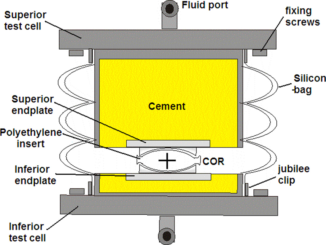
Cross-section of test cell setup up indicating centre of rotation (COR) of the polyethylene core
After measurement, the polyethylene cores were positioned onto the inferior endplate and the test cells were assembled by locating the core onto the superior endplate, and enclosing the test cell in a silicon bag, secured to the test cells with jubilee clips. The test cells were then located in the required test station of the 5-active DOF Spine Wear Simulator (Simulation Solutions, Manchester, UK), secured with two screws on both the inferior and superior test cell. Once all cells had been assembled and inserted into the test station, fluid pipes were connected to the fluid port for each cell and the silicon bag filled with a lubricating solution of calf serum, with a protein concentration of 15g/L. 0.03% (w/v) sodium azide was added to reduce microbial contamination.
The lubricating fluid was retrieved every 1/3 MC and stored frozen for future wear debris analysis. The test cells were then washed through with detergent, soaked in a disinfectant solution (Trigene) for 10 minutes, rinsed with tap water and de-ionised water before refilling with fresh serum solution. At every 1MC time-point, the test cells were taken apart so that thorough cleaning of the cells could take place, including a longer soak (2 hours) in the disinfectant solution. The polyethylene cores were removed, cleaned without scrubbing and then stored at a constant temperature of 22°C and humidity of 45% for 48 hours prior to gravimetric measurement to determine the mass loss. µCT measurements were repeated at 5MC in the 4DOF test and 3MC in the 5DOF test. Wear scars on the polyethylene core were observed and traced with a non-permanent marker pen, in order to photograph at each 1MC time point. The marker pen was thoroughly removed with iso-proponal prior to re-assembling the test cells. These images were then analysed for wear area using ImageProPlus® (Media Cybernetics Inc., Bethesda, MD, USA).
The 4DOF conditions applied axial loading, flexion-extension, lateral bending and axial rotation to each of the six actively tested implants. A seventh disc was tested under only axial loading to account for mass change due to fluid uptake alone. Axial loading was applied using a sinusoidal input with a minimum of 600N and maximum of 2000N, at a rate of 2Hz. The motions were also sinusoidal with a frequency of 1Hz, with flexion-extension of +6°/-3° and lateral bending and axial rotation of ±2° (Figure 2).
Figure 2.
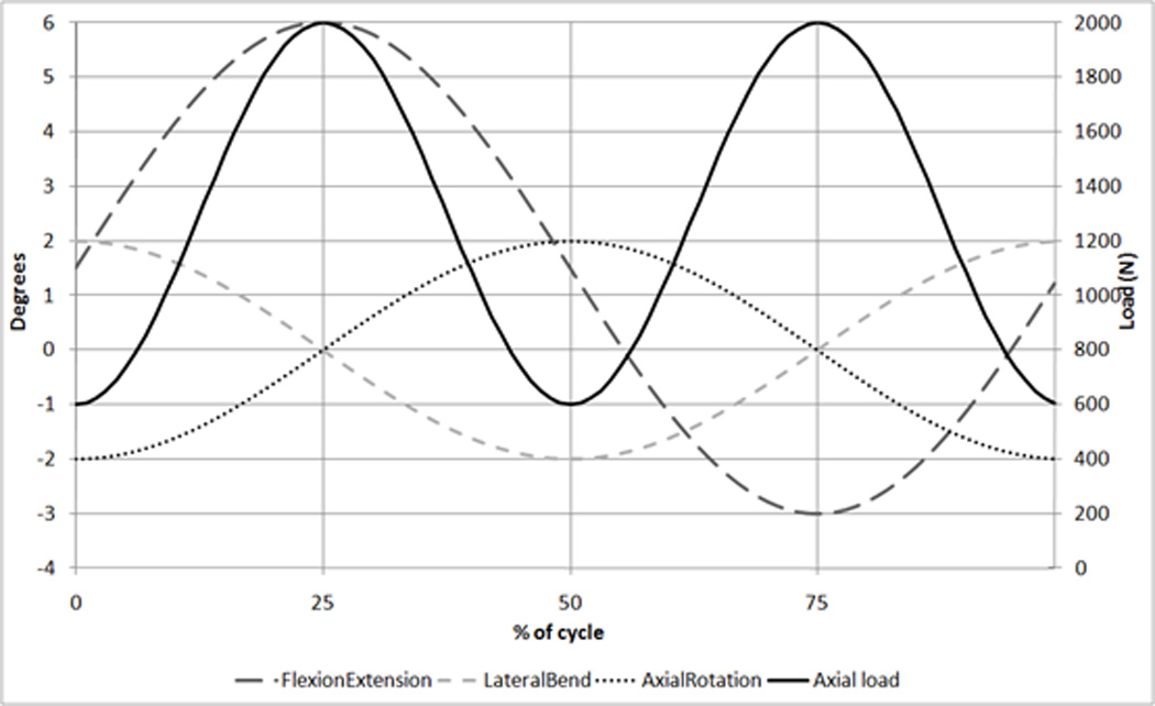
ISO Wear testing inputs [12] showing Flexion/Extension, Lateral bend, Axial rotation (all in degrees) and Axial load (N)
The 5DOF condition test followed the same procedure as the 4DOF ISO test, but the six implants were tested with an additional AP shear displacement of +2mm/−1.5mm (where + is anterior and − is posterior). These displacement values were based upon values published in the literature for the native disc [17, 18]. It was designed so that the AP displacement peaks were coincident with the axial load peaks, similar to previous studies undertaken by the authors [19]. The test was performed under these conditions to 5MC in order to provide direct comparison to the 5MC 4DOF tests on the Charité. The AP displacement was then decreased by a factor of two for 2MC (+1mm/−0.75mm) and then increased by a factor of two for 2MC (+4mm/−3mm) in order to investigate the effect of magnitude of this AP displacement (Figure 3). This increased condition was continued to 3MC as wear rates were not consistent in the first 2MC.
Figure 3.
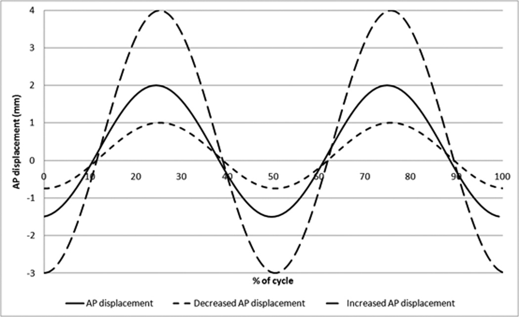
AP shear displacement input for 5DOF tests
µCT scans were evaluated for dome-dome height and rim height (Figure 4) at each measurement point, and the dome penetration rate and rim penetration rate per million cycles calculated. µCT scans of explanted discs studied at Drexel University School of Biomedical Engineering [10] were evaluated for the same parameters. Height losses of the explanted discs were calculated from the original disc geometry, taken from engineering drawings.
Figure 4.
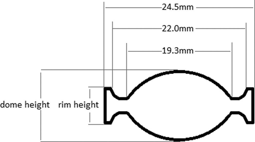
Definition of dome height and rim height on section view of Charite, with dimensions for the dome and rim for the Size 2 Charite implant
Student’s t-tests (SPSS for Windows, Rel 12.0.0 2003, Chicago, SPSS Inc) were used to compare the mean wear measurements from both tests, for both the gravimetric andvolumetric measurements.
Results
The 4DOF test produced an average wear of 12.2±1.0mg/MC over the 5MC test run (Figure 5). The total average specimen wear mass loss was equal to 61.0±4.8mg. The 5DOF test produced an average wear rate of 22.3±2.0 mg/MC over the 5MC test run (Figure 5, Figure 6), a significant increase in the mean wear rate (p<0.01). The total average specimen wear mass loss was equal to 111.5±6.5mg. Decreasing the AP shear input produced a mean wear rate of 24.3±4.9 mg/MC over the 2MC, which was not significantly different from the ‘standard’ AP input (p=0.25). Increasing the AP shear input produced a mean wear rate of 29.1±7.6mg/MC, which was significantly higher (p<0.01) but this increase was dominated by the final million cycles, which had a wear rate of 34.7±11.1mg/MC.
Figure 5.
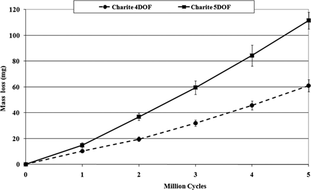
Mass loss results for 4DOF and 5DOF Charité wear tests
Figure 6.
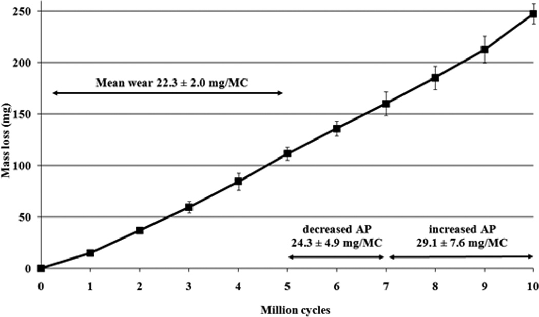
Mass loss results for 5DOF input conditions under standard AP input, decreased AP input and increased AP input
The µCT volumetric measurements found volumetric wear rates of 14.4±5.6mm3 for 4DOF at 5MC, compared to 25.3±4.2mm3 for 5DOF at 3MC, again highlighting the higher wearing 5DOF condition. The µCT reconstruction images (Figure 7) show an example of an unworn disc at 0MC, a 4DOF worn disc at 5MC and a 5DOF worn disc at 3MC. Mean dome penetration rate (Figure 8) and mean rim penetration rate (Figure 9) was calculated for 4DOF and 5DOF tests (in mm/MC) and for explanted components (in mm/year).
Figure 7.
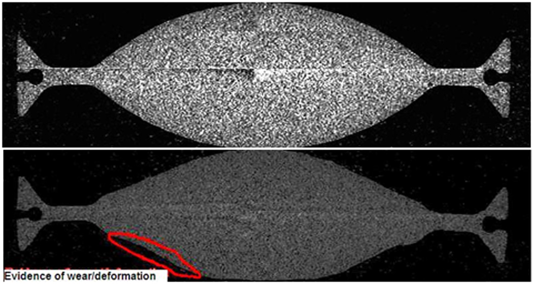
µCT images for unworn and 4DOF tested discs showing shapes changes due to wear and/or deformation
Figure 8.
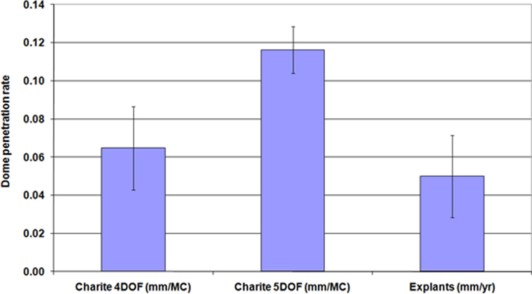
Mean dome penetration rate (±standard deviation) for the 4DOF and 5DOF simulations (mm/MC) and Explanted components (mm/year)
Figure 9.
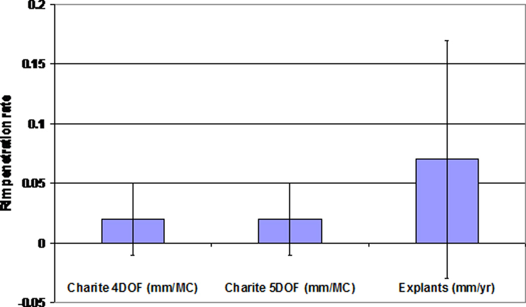
Mean rim penetration rate (± standard deviation) for the 4DOF and 5DOF simulations (mm/MC) and Explanted components (mm/year)
Wear scar traces (Figure 10) showed a total worn area (identified by polishing and a lack of machining marks) and a centralised area of damage (identified by a lack of machining marks, but not polished). The total worn area was significantly larger on the superior surface compared to the inferior surface in both the 4DOF test (p=0.03) and 5DOF test (p=0.01). The total worn area was larger in the 5DOF test than the 4DOF test (p=0.01).
Figure 10.
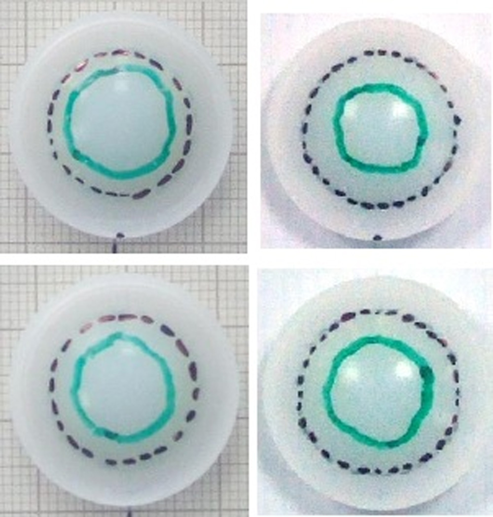
Wear scar traces of inferior surface (bottom) and superior surface (top) a 4DOF disc (left) and 5DOF disc (right)
Discussion
Under 5DOF condition tests on the Charite, the wear rate increased significantly when compared to 4DOF tests on the same simulator. The results presented in this paper are in direct contrast to previously published 5DOF input conditions on the ProDisc TDR, which were undertaken with load rather than displacement control. Although being made of the same bearing materials, the design philosophy of the Charité and ProDisc is different; the Charite has two articulations and is capable of rotations and translations, whereas the ProDisc has a single articulation and is capable of only rotation. Under 4DOF and 5DOF, the wear of the ProDisc has been shown not to be statistically different [19]. It is proposed that under 4DOF, the Charité exhibits preferential articulation at the superior surface, becoming almost a single-bearing [20]. This may explain the similarity of the wear rate of the ProDisc and Charité under 4DOF conditions in studies by the authors [19] and others [13–15]. With the addition of a 5th DOF, the motion is shared between the two bearing surfaces more evenly [21] and therefore the wear rates are altered compared to 4DOF conditions. Wear scar traces showed an increasing contact area on both the superior and inferior surfaces in the 5DOF tests. Increasing contact areas have been shown to affect wear rates in PE as wear is pressure dependent in PE/metal bearing systems [22].
The presence of the AP displacement increased the wear rate in the Charite, but the magnitude of the displacement did not seem to have an effect when comparing between the standard AP and decreased AP displacements, but wear was significantly increased in the increased AP displacement. Larger AP motions would require deformation of the rim and/or slight dislocation, which may explain the increasing wear due to mechanical failures of the PE, since there was visual evidence of cracking and delamination of the PE occurring along with deformation of the rim. This was consistent with explant studies, which in particular showed failure of the core rim [10], which was not evident in 4DOF in-vitro wear simulations.
It is acknowledged that the AP displacement input in this test was different for the previously reported ProDisc, with the ProDisc 5th DOF being run under load-control, and the Charité tests being run under displacement control. The justification for this is that as the ProDisc is not free to move and excessive displacements would have caused non-physiological motions in which subluxation and hence edge loading would occur. Conversely, in the case of load-control of the Charite, excessive loads would cause the Charite to dislocate. These exaggerated motions would in turn lead to structural damage of the polyethylene, not related to normal wear. The AP load was measured during this test on the Charité, and a typical mean output plotted for each 1/3MC (Figure 11). The AP load followed a similar sinusoidal pattern, with similar magnitudes to those input in the previous ProDisc study [19], showing that the two input conditions are equivalent.
Figure 11.
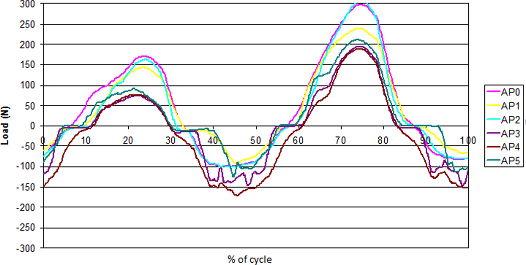
AP load cell feedback over one cycle during the 5DOF test for each of the 6 active stations (AP0-AP5)
It is also acknowledged that, physiologically, anterior load/displacement may be in phase with both axial load and peak flexion [23], which shows two peaks of flexion per cycle. In this study, because the ISO input is sinusoidal with only one peak of flexion per cycle; it is coincident with both peak flexion and peak extension. However, further changes to the ISO input conditions in the 5DOF test would have made it difficult to compare to the 4DOF conditions, and so AP displacement was kept in phase with axial load, meaning that its relationship to flexion seems nonsensical.
Using the µCT scan data of the in-vitro and explanted discs [24], a dome penetration rate was calculated (either per MC or per year). The mean penetration rate per year of the explants was not significantly different from that mean penetration rate per million cycles of the in-vitro tested discs produced in either the 4DOF tests (p>0.99) or 5DOF tests (p=0.08), despite the significant difference between the 4DOF and 5DOF conditions. This suggests that 1MC could be equivalent to 1 year in-vivo, although the large variation and small sample size of the explant data makes it difficult to draw significant conclusions.
Increased numbers of explanted components, both those deemed as failures and those retrieved at post-mortem, are needed to establish what is ‘normal’ wear that is representative of the population. However, ‘normal’ may be very difficult to define in TDR due to a large number of differing input factors. As well as the differences between design materials and design philosophies, there are the idiosyncrasies from patient to patient that affect the TDR tribological environment, including differing biomechanical factors, activity levels, the presence of several different implantation levels and differing vertebral recruitment patterns [25].
The explanted discs suffered more severe damage than any of the in-vitro tested discs, which may be a result of the 4DOF and 5DOF test conditions not fully representing the conditions in-vivo, such as variations in surgical placement, and extremes of load and motions. In addition, all of these explants had been removed at revision surgery, and so by their nature may be poorly-performing discs. A proportion (32%) of the discs were also gamma-irradiated in air, which none of the in-vitro discs were, a process known to increase the brittleness of PE components, increasing the likelihood of fatigue fractures and increasing wear [26]. Gamma-irradiation is no longer used for sterilisation of orthopaedic implants.
The µCT measurement has not been exploited to its full potential. The dome measurement is only a measurement of the maximum (dome-to-dome) penetration, and although clinically relevant in order to relate to in-vivo endplate separation, it does not necessarily reflect wear rate. Further image processing and image registration may allow investigation of PE density changes and overall shape change, relating to both creep and wear.
Under identical 4DOF conditions, the wear of the ProDisc and Charité were not statistically different. The addition of a 5th DOF to testing inputs on the ProDisc had no statistical significance, but in the case of the Charite, the wear rate almost doubled. Although the ISO wear simulation is a fair representation of clinical gait [23], and it produces wear results that are consistent with explanted discs, the simulation will not reflect the variability in tribological environment which may account for the significant differences in wear rates between individual explant components, which is a wider concern for all joint arthroplasty simulations investigating wear. Further, the devices may demonstrate increased damage when the device undergoes extreme motions causing the metallic endplate to impinge on the UHMWPE out surface. This highlights the importance of clinically relevant testing regimens, and that clinically relevant test inputs may be different for dissimilar design philosophies. A sound understanding of device biomechanics and improved in-vivo data collection is necessary to be able to determine the most clinically relevant test inputs, including for more everyday activities, more complex loading cycles and estimations for different kinds of patients.
Key points.
Anterior-posterior shear was added to standard 4DOF testing inputs prescribed by ISO18192, for in-vitro wear testing of the Charité lumbar total disc replacement.
The addition of anterior-posterior shear significantly increased the in-vitro wear rates of the Charité lumbar disc replacement, which is in direct contrast to similar studies of the ProDisc-L.
Both 4DOF and 5DOF wear testing inputs produce height losses that are not statistically different from explanted discs.
Clinically relevant wear testing inputs may have to be different for dissimilar design philosophies (such as fixed bearing and mobile bearing TDR).
Acknowledgements
This work is supported by the National Institutes of Health grant R01-AR052653 as part of a collaboration of the University of Leeds, University of Iowa, and Spine Centre Munich. The Charité discs and engineering drawings of the Charité discs were provided by DePuy Spine, Raynham, MA. The µCT scans of explanted discs were provided by Steven Kurtz, Drexel University School of Biomedical Engineering. John Fisher is an NIHR senior investigator and supported through NIHR LMBRU Leeds Biomedical Musculoskeletal Research Unit. Dr Prokopovich, Professor Fisher, Professor Ingham, Dr Tipper and Professor Hall are supported through the Leeds Centre of Excellence in Medical Engineering, WELMEC, funded by the Wellcome Trust and EPSRC, WT 088908/Z/09/Z.
Footnotes
Publisher's Disclaimer: This is a PDF file of an unedited manuscript that has been accepted for publication. As a service to our customers we are providing this early version of the manuscript. The manuscript will undergo copyediting, typesetting, and review of the resulting proof before it is published in its final citable form. Please note that during the production process errors may be discovered which could affect the content, and all legal disclaimers that apply to the journal pertain.
Disclosures
Professor Fisher is a Director of BITECIC Ltd and Tissue Regenix Ltd and a paid consultant to DePuy International. Professor Ingham is a Director of Tissue Regenix Ltd. Professor Brown is a paid consultant to Smith & Nephew.
The device(s)/drug(s) is/are FDA-approved or approved by corresponding national agency for this indication. Federal funds were received to support this work. No benefits in any form have been or will be received from a commercial party related directly or indirectly to the subject of this manuscript.
References
- 1.Rosen M. Back Pain- report of a CSAG committee on back pain. London: Clinical Standards Advisory Group; 1994. [Google Scholar]
- 2.Frymoyer JW, Cats-Baril WL. An overview of the incidences and costs of low back pain. Orthopedic Clinics of North America. 1991;22(2):263–271. [PubMed] [Google Scholar]
- 3.Katz JN. Lumbar Disc Disorders and Low-Back Pain: Socioeconomic Factors and Consequences. J Bone Joint Surg Am. 2006;88(suppl_2):21–24. doi: 10.2106/JBJS.E.01273. [DOI] [PubMed] [Google Scholar]
- 4.Errico TJ. Why a mechanical disc? Spine Journal: Official Journal of the North American Spine Society. 2004;4(6 Suppl):151S–157S. doi: 10.1016/j.spinee.2004.07.004. [DOI] [PubMed] [Google Scholar]
- 5.Lee CK, Langrana NA. A review of spinal fusion for degenerative disc disease: need for alternative treatment approach of disc arthroplasty? The Spine Journal. 2004;4(6) Supplement 1:S173–S176. doi: 10.1016/j.spinee.2004.07.002. [DOI] [PubMed] [Google Scholar]
- 6.Park P, et al. Adjacent segment disease after lumbar or lumbosacral fusion: review of the literature. Spine. 2004;29(17):1938–1944. doi: 10.1097/01.brs.0000137069.88904.03. [DOI] [PubMed] [Google Scholar]
- 7.Zigler J, et al. Spine Arthroplasty 5: Global symposium on motion preservation technology. New York, USA: Spine Arthroplasty Society; 2005. Lumbar total disc replacement: a 2 to 3 year report from centers in the United States clinical trial for the ProDisc-II prosthesis. [Google Scholar]
- 8.van Ooij AM, et al. Polyethylene Wear Debris and Long-term Clinical Failure of the Charite Disc Prosthesis: A Study of 4 Patients. Spine. 2007;32(2):223–229. doi: 10.1097/01.brs.0000251370.56327.c6. [DOI] [PubMed] [Google Scholar]
- 9.Hallab NJ, Cunningham BW, Jacobs JJ. Spinal implant debris-induced osteolysis. Spine. 2003;28(20):S125–S138. doi: 10.1097/00007632-200310151-00006. [DOI] [PubMed] [Google Scholar]
- 10.Kurtz SM, et al. Polyethylene wear and rim fracture in total disc arthroplasty. Spine Journal: Official Journal of the North American Spine Society. 2007;7(1):12–21. doi: 10.1016/j.spinee.2006.05.012. [DOI] [PubMed] [Google Scholar]
- 11.ISO/DIS 18192-1. 2005. Implants for surgery - Wear of total intevertebral spinal disc prostheses - Part 1: Loading and displacement parameters for wear testing and corresponding environmental conditions for tests. [Google Scholar]
- 12.ASTM F 2423-05. 2005. Standard Guide for Functional, Kinematic, and Wear Assessment of Total Disc Prostheses. [Google Scholar]
- 13.Bushelow M, et al. Spine Arthroplasty Society 8: global symposium on motion preservation technology. Miami, USA: 2008. Wear testing of metal-on-metal total disc replacment components. [Google Scholar]
- 14.Nechtow W, et al. Orthopaedic Research Society Meeting. Chicago, IL: 2006. IVD replacement mechanical performance depends strongly on input parameters. [Google Scholar]
- 15.Wright TM, et al. Spine Arthroplasty 6: Global symposium on Motion preservation technology. Montreal, Quebec, Canada: Spine Arthroplasty Society; 2006. Retrieval and wear analyses of ProDisc lumbar disc implants. [Google Scholar]
- 16.Vicars R, Fisher J, Hall RM. The accuracy and precision of a micro computer tomography volumetric measurement technique for the analysis of in-vitro tested total disc replacements. Proceedings of the Institution of Mechanical Engineers Part H - Journal of Engineering in Medicine. 2009;223 doi: 10.1243/09544119JEIM515. [DOI] [PubMed] [Google Scholar]
- 17.Pearcy MJ. Stereo radiography of lumbar spine motion. Acta Orthopaedica Scandinavica Supplementum 212. 1985;Volume 56 doi: 10.3109/17453678509154154. [DOI] [PubMed] [Google Scholar]
- 18.Campana S, de Guise JA, Rillardon L, et al. Lumbar intervertebral disc mobility: effect of disc degradation and of geometry. Eur J Orhtop Surg Traumatol. 2007;17:533–541. [Google Scholar]
- 19.Vicars RE, Hyde PJ, Brown TD, Tipper JL, Ingham E, Fisher J, Hall RM. The effect of anterior-posterior shear load on the wear of the ProDisc-L TDR. Eur Spine J. 2010;19(8):1356–1362. doi: 10.1007/s00586-010-1396-8. [DOI] [PMC free article] [PubMed] [Google Scholar]
- 20.Goreham-Voss CM, Vicars RE, Hall RM, et al. Preferential superior surface motion in wear simulations of the Charite total disc replacement. Eur Spine J. 2010 Jun; doi: 10.1007/s00586-010-1490-y. Epub ahead of print. [DOI] [PMC free article] [PubMed] [Google Scholar]
- 21.Vicars R, Chyuan-Loo F, Goreham-Voss, et al. Orthopaedic Research Society Annual Meeting. New Orleans: 2010. Mar, Experimental motion analysis of a fixed and mobile bearing TDR. [Google Scholar]
- 22.Kang L, Galvin AL, Brown TD, Fisher J, Jin ZM. Wear simulation of ultrahigh molecular weight polyethylene hip implants by incorporating the effects of cross-shear and contact pressure. Proceedings of the Institution of Mechanical Engineers Part H - Journal of Engineering in Medicine. 2008;222(7):1049–1064. doi: 10.1243/09544119JEIM431. [DOI] [PubMed] [Google Scholar]
- 23.Callaghan JP, Patla AE, McGill SM. Low back three-dimensional joint forces, kinematics, and kinetics during walking. Clinical Biomechanics. 1999;14(3):203–216. doi: 10.1016/s0268-0033(98)00069-2. [DOI] [PubMed] [Google Scholar]
- 24.Kurtz SM, Patwardhan A, MacDonald D, et al. What is the correlation of in vivo wear and damage patterns with in vitro TDR motion response? Spine. 2008;33(5):481–489. doi: 10.1097/BRS.0b013e318165e3be. [DOI] [PMC free article] [PubMed] [Google Scholar]
- 25.Hall RM, Brown TD, Fisher J, et al. Introduction to lumbar total disc replacement: factors that may affect tribological performance. Proceeding of the Institute of Mechanical Engineering Part J: Engineering Tribology. 2006;(220):775–786. [Google Scholar]
- 26.Ries MD, Weaver K, Rose RM, et al. Fatigue strength of polyethylene after sterilisation by gamma irradiation or ethylene oxide. Clin Orthop Relat Res. 1996;(333):87–95. [PubMed] [Google Scholar]


