

Abstract
The biological central pattern generator (CPG) integrates open and closed loop control to produce over-ground walking. The goal of this study was to develop a physiologically based algorithm capable of mimicking the biological system to control multiple joints in the lower extremities for producing over-ground walking. The algorithm used state-based models of the step cycle each of which produced different stimulation patterns. Two configurations were implemented to restore over-ground walking in five adult anaesthetized cats using intramuscular stimulation (IMS) of the main hip, knee and ankle flexor and extensor muscles in the hind limbs. An open loop controller relied only on intrinsic timing while a hybrid-CPG controller added sensory feedback from force plates (representing limb loading), and accelerometers and gyroscopes (representing limb position). Stimulation applied to hind limb muscles caused extension or flexion in the hips, knees and ankles. A total of 113 walking trials were obtained across all experiments. Of these, 74 were successful in which the cats traversed 75% of the 3.5 m over-ground walkway. In these trials, the average peak step length decreased from 24.9 ± 8.4 to 21.8 ± 7.5 (normalized units) and the median number of steps per trial increased from 7 (Q1=6, Q3 = 9) to 9 (8, 11) with the hybrid-CPG controller. Moreover, these trials, the hybrid-CPG controller produced more successful steps (step length ≤ 20 cm; ground reaction force ≥ 12.5% body weight) than the open loop controller: 372 of 544 steps (68%) versus 65 of 134 steps (49%), respectively. This supports our previous preliminary findings, and affirms that physiologically based hybrid-CPG approaches produce more successful stepping than open loop controllers. The algorithm provides the foundation for a neural prosthetic controller and a framework to implement more detailed control of locomotion in the future.
1. Introduction
The ability to walk is developed at an early age in most legged species. In vertebrates, a specific pattern of alternating activation of flexor and extensor muscles is generated through the spinal cord to provide sufficient force and appropriate movements necessary for locomotion (Brown 1914). During walking, lower limb movements must be coordinated to produce patterns of swing and stance while maintaining balance. The principal mechanisms underlying the generation and control of locomotion have been studied in detail in animals such as cats (Grillner 1985, Conway et al 1987, Burke et al 2001, Hiebert and Pearson 1999, Prilutsky et al 1996, Grillner and Zangger 1979) and lampreys (Grillner and Matsushima 1991, Islam et al 2006, Mentel et al 2006, Archambault et al 2001).
The spinal central pattern generators (CPGs), located in the cervical and lumbar enlargements, are responsible for the bilateral rhythmic outputs activating flexor and extensor muscles in the upper and lower extremities (Yamaguchi 2004). Other important locomotor centres are located in the midbrain locomotor region. CPGs controlling functions such as swallowing and breathing are also located in the brain stem (Dick et al 1993). The CPG controlling locomotion in the lower extremities is thought to be located in the lumbosacral region of the spinal cord where descending signals from the brain as well as afferent feedback are integrated to generate muscle activation patterns observed during walking (Kiehn 2006). The CPG utilizes feed forward control (defined as open loop control) using predefined timing values to establish a timing pattern (McCrea and Rybak 2007). Spinal and supraspinal centres process the sensory feedback signals to adjust the output of the CPG (defined as closed loop control). This feedback allows the CPG to adjust its output based on external (e.g. environmental) and internal (e.g. fatigue) perturbations. Support for the existence of the CPG comes from the observations of rhythmic walking movements after low thoracic spinalization in cats and after spinal cord injury (SCI) in humans (Hultborn and Nielsen 2007).
Individuals with SCI may lose the ability to walk due to damaged neural communication between the brain and locomotor CPG. People with incomplete SCI retain some residual neural connections and often may be able to walk with impairments. If the SCI is complete, the individual loses all functionality and control of the lower extremities. Attempts have been made to restore locomotion through functional electrical stimulation (FES) (Kobetic et al 1997, Thrasher and Popovic 2008). The systems available restore limited standing and gait function, and require user input to determine the stimulation patterns. In addition, the systems normally do not contain sensory feedback to respond to changes in the environment.
The proposed control algorithm in this work applied a complex state-system to produce feedback controlled locomotion patterns across several joints. The application of state-based control for walking neuroprostheses was first proposed by Tomovic and Mcghee (1966), a few years after Mealy and Moore published some of the first state-based automata (Mealy 1955). Since Tomovic and Mcghee, state-based control, while common in other fields of engineering, has only been implemented with limited state spaces or with single joint control in walking neuroprostheses (Crago et al 1996). Recent work by Quintero et al (2010) has shown that state-based control of quadriceps stimulation and orthoses can restore walking by using four states to activate the legs sequentially. Currently, most state-based FES walking systems do not utilize sensory feedback (Sweeney et al 2000). In addition to a larger state space and multi-joint sensory feedback control, the controller developed as part of this work can be reconfigured to elicit several types of locomotion using the same framework (e.g. running).
Other locomotion controllers have been developed which attempt to restore complete gait function by emulating the functionality of the CPG (Guevremont et al 2007). The goal of such systems is to restore locomotion while requiring minimal conscious effort to operate and generate sufficient forces to support body weight (BW). The controller designed by Guevremont et al (2007) used IF-THEN statements to determine the intramuscular stimulation (IMS) patterns in selected hind limb muscles of cats. Open loop or closed loop control were implemented individually for determining the transition between a swing and stance state. Open loop control used intrinsic timing as feed forward control to determine the swing and stance state transitions. Closed loop control used sensory feedback information to perform these same transitions. Each control paradigm had its limitations, and a combined controller was briefly tested and showed promising results for producing safe over-ground walking. Prochazka et al (2002) demonstrated the utility of open and closed loop control during locomotion in their computer model of a cat. Sensory feedback was also shown to be important in computer simulations of stepping (Ekeberg and Pearson 2005). Another controller implemented by Vogelstein et al (2008) configured a silicon neural network to emulate functions of the CPG by controlling the movements of several hind limb joints. This controller only used closed loop control to determine transitions between swing and stance but was one of the first neuromorphic devices to instantiate a functional CPG in vivo. Although it was successful at restoring locomotion in an anaesthetized cat, the controller would occasionally become trapped in undesirable states during stance and swing transitions which effectively stopped the over-ground walking. These limitations again emphasized the need for a combined open and closed loop controller and led to the development of the present system which features a larger and more comprehensive state system for precision rule-based control.
Therefore, the goal of this study was to develop a physiologically based control algorithm capable of using intrinsic timing and sensory feedback to control multiple joints in the lower extremities for producing safer over-ground walking than that obtained with an open loop controller. Such a controller was deemed successful if it produced a sufficient level of load bearing force, maintained natural ranges of motion and successfully traversed an over-ground walkway. The algorithm can easily be translated into a silicon chip capable of using a variety of input and output modalities of which certain components have been implemented (Mazurek et al 2010, Mazurek and Etienne-Cummings 2011). This paper describes the proposed locomotion control algorithm and the results of its implementation in vivo. The locomotion controller allowed for comparing two configurations: an open loop controller and a hybrid-CPG controller. The success of each controller depended on its ability to restore over-ground walking while overcoming internal and external perturbations. We hypothesized that the hybrid-CPG would produce more successful over-ground trials compared to the open loop controller. Additionally, the hybrid-CPG controller would generate more steps with adequate load bearing force and these steps would have more natural ranges of motion. Direct comparisons of the efficacy of the controllers were made through analysis of parameters such as BW support, walking speed and limb kinematics.
2. Methods
2.1. Locomotion control algorithm
The locomotion control algorithm was designed as a framework for configuring different implementations of open and closed loop control to shape the output stimulation waveforms. The algorithm consisted of three main components: the control logic, the sensory rules and the stimulation output. These three components are depicted in figure 1.
Figure 1.
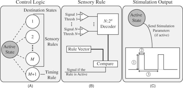
Overview of the components of the locomotion control algorithm. (A) The control logic consisted of an active state and several destination states. One of the destination states was specified by the preset timing rules while the remaining states were specified by certain sensory rules. (B) Each sensory rule consisted of a number of sensory input signals and programmable thresholds which were decoded and corresponded to specific logic functions. If the output of the comparators matched one of the desired output functions, a signal was passed to the control unit to indicate that the rule was active. (C) Each active state contained information about all stimulation output waveforms and whether each output was active or not. The stimulation (1) amplitude, (2) pulse width and (3) frequency were all specified by the active state and were adjusted to produce shaped waveforms.
The control logic (figure 1(A)) contained a programmable state system where transitions between each state were intrinsically timed (in the form of timing rules). The control logic activated multiple joints (ankle, hip and knee) in the lower extremities in an appropriate pattern to generate walking movements and supportive forces. Sensory information (figure 1(B)) adjusted the transitions between certain states and ensured the correct state was active based on the position of the lower limbs. The `active state' was defined as the state that the control logic was currently executing. Each state contained information about which sensory rules were enabled during that phase of the step cycle. The algorithm was configured to have M sensory rules where the limit of the value of M was constrained to the resources available in the system (such as the number of sensory signals, resources for digitizing the signals, etc). Associated with each rule (timing or sensory) was a `destination state' which would become the new `active state' if that rule were activated (figure 1(A)). The rules were organized in a predetermined priority to ensure proper state transitions in the event that two rules were activated simultaneously.
The stimulation output waveforms (figure 1(C)) allowed for increases or decreases in muscle activity by modulating amplitudes after each state transition. Each state corresponded to a specific set of stimulation parameters for all output stimulation channels. These parameters included whether the channel was active or inactive, the stimulation amplitude, the pulse width and the stimulation frequency. The control logic produced the output stimulation waveform according to the parameter values associated with the active state. These changing waveforms aimed to activate different muscle groups at varying stimulation levels as observed during normal locomotion. The output stimulation channels were activated in parallel to reduce potential delays that may be introduced during serial activation of different sites (muscles).
The stability of such a controller was directly related to the configuration of the state system. An unstable controller would demonstrate oscillations between states based on uncertain inputs. This was preventable in the algorithm by appropriately setting the sensory and timing rules to ensure that transitions could only be made in a certain direction. In addition, the timing rules allowed for the controller to transition between states in the event that sensory feedback was insufficient.
2.2. Implemented controller
We implemented two forms of the locomotion control algorithm (open loop and hybrid-CPG) to produce over-ground walking in adult cats. The predetermined state system was the same for both controllers and was developed from known biological descriptions of the cat step cycle as shown in figure 2. Each state corresponded to a specific combination of movements of both hind legs. The initial state generated double stance in both legs to produce standing and weight support, and the remaining eight states (states 2–9) consisted of a symmetrical step cycle. In past experiments (Guevremont et al 2007) the step cycle for each hind leg was divided into two states representing swing and stance. The step cycle in this work used four sub-states (F, E1, E2, E3) as previously defined in humans (Nilsson et al 1985) and cats (Goslow et al 1973) which enabled the representation of more detailed changes in muscle activation and movements during walking.
Figure 2.

Overview of the states for the open loop controller and hybrid-CPG controller. Each controller state represents two sub-states corresponding to a portion of the step cycle in each leg. The sub-state definitions are as follows: F, flexion; E1, foot placement; E2, support; and E3, push-off. The cat enters LE2/RF (state 2 with the left (L) cat leg in E2 and the right (R) leg in F) and advances through the step cycle based on preset timing or activated sensory rules. Both controllers begin a trial in double stance (state 1) denoted by LE2/RE2 for the left and right legs, respectively. Black arrows symbolize intrinsically timed transitions used for both controllers. Grey diamonds denote sensory feedback rules and their respective pathways for both legs with the rules as follows: swing-to-stance (A), stance-to-swing (B) and fatigue compensation (C). The sensory rules were only applicable to the hybrid-CPG controller.
The swing portion of the step cycle consisted of lifting and moving the leg forward (F). The stance phase followed by extending the knee to place the foot on the ground (E1), activating the knee and ankle extensor muscles for weight support (E2), and adding the activation of hip extensors and increasing the activation in ankle extensors to produce propulsive force and forward progression of the body (E3 (Yang and Winter 1985)). The relative duration of each sub-state to the total step period could be adjusted for different gaits and is thought to be controlled by intrinsic timing circuits located within the spinal cord (Grillner 1985, McCrea and Rybak 2008, Yakovenko 2011). In this work, the durations of these sub-states for each leg were 20%, 20%, 20% and 40% of the total step period (for F, E1, E2 and E3, respectively) for the intrinsic timing rules. The walking cycle duration was set to 1.5 s for both the open loop and hybrid-CPG controllers to resemble adult cats walking at slow to moderate speeds. The timing of the phases of the hybrid-CPG controller could be modified as necessary based on sensory input. In order to maintain controller stability, measures were taken to ensure that the controller did not enter states that would unload both legs (such as double flexion, F). Also, when sensory feedback was activated, sensory information would only be interpreted within the context of a specific state. The open loop controller advanced through the states shown in figure 2 using the preset timing rules. For the hybrid-CPG, the additional sensory feedback rules were translated into three specific IF-THEN statements. These rules monitored the ground reaction forces (GRFs) and range of backward extension which governed the transition from swing-to-stance (E1 to E2), the transition from stance-to-swing (E3 to F) and fatigue compensation rule. The details of each rule are described in sections 2.2.1–2.2.3. The purpose of the rules was to adapt the walking cycle to different perturbations. Sensory signals were recorded from accelerometers, gyroscopes and force plates, and were processed every 31 ms corresponding to the update period of the controller. The accelerometers (located on the foot and shank) and gyroscopes (located on the foot) provided information about limb angle while the force plates provided information about the GRF of each leg. The diagram in figure 2 depicts how certain sensory rules were enabled for certain states and disabled for others.
For both the open loop and hybrid-CPG controllers, IMS was controlled to activate hip, knee or ankle flexor and extensor muscles of the hind limbs according to the `active state' of the control logic. Stimulation amplitudes were set to generate the desired movement and force. The initial amplitude of stimulation for the hip, knee and ankle flexor and extensor muscles in each leg was based on observation of the evoked movements and the level of force generated. Initially, the minimal level of stimulation capable of producing weight-bearing and propulsive forces during the E2 and E3 phases was chosen for the hip, knee and ankle extensor muscles. Stimulation amplitudes for the flexor muscles were chosen to produce adequate upward and forward movements of the hind limb. This balanced combination of stimulation channels generated the synergistic movements necessary to evoke over-ground walking. Table 1 specifies which leg movements were associated with each sub-state of the step cycle. Note that the same flexor or extensor muscle (stimulation channel) could be active for multiple states in both controllers but the amplitude of activation varied between states. Upon transitioning between states, the stimulation amplitudes from the old active state were ramped to the amplitudes set in the new active state (over 93 ms). This resulted in a shaped stimulation waveform resembling natural electromyographic recordings (EMG) of muscle activation (Guevremont et al 2007).
Table 1.
Flexor and extensor muscles active during each state of the step cycle.
| Step cycle state | Flexion | Extension |
|---|---|---|
| F | Hip, knee, ankle | None |
| El | Hip, ankle | Knee |
| E2 | None | Knee, ankle |
| E3 | None | Hip, knee, ankle |
2.2.1. Stance-to-swing rule
The transition from stance-to-swing occurred when the leg generating the propulsive force extended backwards and was no longer in a supportive position. The rule was implemented using the following IF-THEN statement:
IF limb angle < threshold
THEN transition from state E3 to state F.
2.2.2. Swing-to-stance rule
The swing phase of the step cycle was considered to be completed when the leg had adequately moved forward as determined by the limb angle (relative to the hip). When the limb angle exceeded a predetermined threshold, the E1 state was terminated. This rule was implemented using the following IF-THEN statement:
IF limb angle > threshold
THEN transition from state E1 to state E2.
2.2.3. Fatigue compensation rule
Over time it was visually observed that the supportive force generated by the hind limbs declined due to muscle fatigue. The purpose of the fatigue rule was to adjust the stimulus amplitude to the extensor muscles to ensure that the cat could propel itself adequately across the walkway. The level of the supportive force was continuously monitored and if the peak force dropped below a certain threshold during the E3 phase, the rule was enabled and acted to increase the amplitude of stimulation to the knee extensor muscle by 30% in the subsequent E2 state. The increase in stimulation amplitude was maintained for the remainder of the trial (i.e. until the cat traversed the walkway). The reason for monitoring E3 and changing E2 instead of only monitoring E2 across steps was because of the physiological delay (approximately 60–80 ms) between the onset of stimulation and force generation. This rule was implemented using the following IF-THEN statement:
IFmax (ipsilateral force during E3) < threshold
THEN increase stimulation
amplitudes of all subsequent E2 by x%.
The value of x was typically 30%.
2.3. Animal preparation
For detailed animal preparation please see Guevremont et al (2007). All experimental procedures were approved by the University of Alberta's Animal Care and Use Committee. The cats were anaesthetized using isoflurane inhalation and subsequently transitioned to sodium pentobarbital. The cat remained under anaesthesia for the duration of the experiment. Pairs of stimulation electrodes were inserted percutaneously into eight muscles of each leg (tibialis anterior, gastrocnemius, vastus medialis, vastus lateralis, rectus femoris, sartorius (anterior compartment), semitendinosus and semimembranosus (anterior compartment)). The cat was then transferred to an instrumented walkway and partially suspended in a cart-mounted sling. Due to the experimental setup, the sling supported 75% of the cat's weight (head, trunk and abdomen). Therefore, 12.5% of BW was considered full load bearing support for a single hind limb. The mass of the cart and the equipment on it was offset by a pulley system (unloading between 400–600 g, ~5% of the combined cat and cart weight) to reduce the effect of static friction. The unloading was initially chosen by applying incremental weights to the pulley system until the cart began to move even without muscle activation. The chosen pulley weight was 100 g less than the unloading level at which the cart moved without muscle activation.
The walkway contained a variable friction profile to which the control rules had to accommodate. The friction around the middle section of the walkway was less than that at the beginning or endpoint (figure 3).
Figure 3.
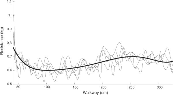
Resistance profile of the walkway. The cart was loaded with 5.5 kg to represent the combined weight of a cat and equipment during an experiment. The force required to move the cart was measured over four trials (light traces) and fitted with a trend line (bold line) to represent the resistance profile of the walkway. The initial peak resistance was required to overcome static friction.
2.4. Stimulation and sensors
Walking patterns were produced by direct bipolar electrical stimulation of the target muscles using trains of biphasic charge-balanced pulses (62 Hz, up to 20 mA, 100 μs) in a similar fashion to that described in Guevremont et al (2007). The electrodes were pairs of 34AWG sterilized 9-strand stainless steel Cooner wire (Cooner Wire Inc., Chatsworth, CA, USA), Teflon insulated except for 3 to 4 mm exposure at the tips. The distance between the tips within a muscle was approximately 1 cm and the AC resistance was approximately 1 kΩ. The wires were positioned near the motor points according to anatomy reference guides. Location was verified using 1 s stimulation trains and electrodes were readjusted if necessary. This typically resulted in maximal threshold currents of 2–3 mA, and maximal force generation was achieved with amplitudes of 6–8 mA, thus leaving ample room for increases in stimulation amplitude (up to 20 mA) during the course of the experiment. This process ensured that electrode placement was not the reason for failed trials in any of the experiments. Stimulation was produced by a parallel command stream using a National Instruments DAC (PCI-67xx Series, National Instruments Corp., Austin, TX, USA) connected to modified EMS-6500 stimulators (Electrostim Medical Services, Tampa, FL, USA). The parallel command stream was created in real time by the two controller algorithms. Amplitudes were chosen to recreate estimates of the continuously graded EMG patterns as observed by Goslow et al (1973) and provide adequate forward propulsion. Muscles were grouped according to a common function or synergy as described in table 1.
Accelerometers and gyroscopes were attached to the hind limbs for recording signals appropriate for triggering sensory rule transitions. Tri-axial accelerometers were fixed to both the shank and the foot of each leg (the X direction was horizontal in the forward direction of movement, the Y direction was vertical). The gyroscopes were placed on each foot proximal to the accelerometers (figure 4). The gyroscope signals were integrated to provide foot angle. Due to the drift caused by the integration of the gyroscope signal, the angle signals were reset at the beginning of the stance phase (E2) of each limb. A custom 3.5 m walkway was instrumented with separate force plates for each leg. The downward forces perpendicular to the walkway were used as the GRF. Gyroscope, accelerometer and GRF recordings were acquired using a Cerebus (Blackrock Microsystems, Salt Lake City, UT, USA) data acquisition system at 1000 samples s−1. The data were streamed from Cerebus into Matlab (The MathWorks Inc., Natick, MA, USA) to be processed in real time by custom written software. All gyroscope, accelerometer and force data were recorded for each trial and a moving average filter with a window length of 120 ms was applied to smooth the signals for use in the sensory rules.
Figure 4.
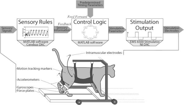
Experimental setup. The anaesthetized cat was suspended in a cart-mounted sling over a walkway and the right hind limb was videotaped for motion tracking. IMS electrodes activated the hind limbs to propel the cat along the walkway. Sensory feedback was provided by accelerometers, gyroscopes and force plates. These sensory signals were used in the hybrid-CPG controller for different feedback rules based on appropriate threshold values. If activated, the feedback rules overrode the timing rules and allowed the hybrid-CPG controller to adjust the stimulation output. The signals were digitized using a Cerebus (BrainGate Co. LLC, Ponte Verdra Beach, FL, USA) ADC and streamed into custom Matlab (MathWorks Inc., Natick, MA, USA) software which utilized National Instruments (National Instruments Corp., Austin, TX, USA) DAC to send stimulation parameters to modified EMS 6500 stimulators.
Reflective markers were placed on the right hind limb of the cat to indicate the iliac crest, hip, knee, ankle and metatarsophalangeal joints. The positions of these markers were used to delineate joint position and leg movement, but were not applied to any sensory feedback rules. The length of the walkway was captured by a high speed JVC (JVC Americas Corp., Wayne, NJ, USA) camcorder (120 frames s−1) positioned 4.5 m away from the midpoint of the walkway with the lens parallel to the walkway.
2.5. Experimental procedures
Before testing either the open loop or hybrid-CPG controller, appropriate stimulation amplitudes were established for the different step cycle sub-states in each limb. For a typical cat, the amplitudes for each channel (muscle) across a walking cycle are shown in figure 5. Once these values were deemed appropriate for generating the desired functional movements and forces, the open loop controller was tested to generate over-ground walking. During these trials, the sensory signals from the accelerometers, gyroscopes and force plates were recorded and analysed to determine appropriate threshold values to apply to the feedback rules in the hybrid-CPG controller. Upon determining these thresholds, the hybrid-CPG controller was tested to produce over-ground walking. A total of seven experiments were conducted with five cats (male or female, 3.5–4.4 kg).
Figure 5.

Typical stimulation amplitudes across one step cycle. Each channel is shown with its stimulation amplitudes and duration in grey. Some ramping occurs at the onset and offset of a channel's activation. Vertical shading shows the timing and duration of the states within the walking cycle. Vastus medialis and semitendinosus could not be targeted in this animal and have been disabled for the experiment. LHF = left hip flexor = sartorius (anterior compartment), LHE = left hip extensor = semimembranosus (anterior compartment), LKF = left knee flexor = semitendinosus, LKE = left knee extensor = vastus lateralis, LAF = left ankle flexor = tibialis anterior, LAE = left ankle extensor = gastrocnemius, LRF = left rectus femoris, LVM = left vastus medialis. The last eight channels are the equivalent muscles for the right side.
2.6. Data analysis
Upon completion of trials with both the open loop and hybrid-CPG controllers, the recorded data from accelerometers, gyroscopes and force plates were compared between controllers. A trial was considered successful if the cat began <10 cm from the start of the walkway and walked at least 75% across the length of the walkway (resulting in a total distance of at least 2.24 m). For each successful trial, the force and length of each step was analysed to determine which controller produced a greater proportion of successful steps. The minimal load bearing force during any point of the stance phase had to exceed 12.5% of BW (due to our setup) to ensure that the knees would not buckle. The step also could not be longer than 20 cm with reference to the hip, ensuring a physiologically realistic range of motion by similar sized cats (3 kg) walking at approximately 0.20 m s−1 (Halbertsma 1983). With our experimental setup, a stride length exceeding 20 cm was an indication of excessive backward extension of the hind limb at the end of the stance phase resulting in a loss of supportive force and/or slipping of the foot. The percentage of successful steps within trials where the cat walked over 75% of the walkway length was used to judge the effectiveness of each controller configuration in producing walking. Marker positions were digitized from the high speed recordings using custom Matlab software (MotionTracker2D) written by Dr Douglas Weber (University of Pittsburgh, Pittsburgh, PA, USA). Each frame was calibrated using a set of reference markers to correct for offset in the camera angle. Joint angles and limb representations were calculated from the marker locations. Limb angle (vector from the hip to the metatarsophalangeal joint) was measured with respect to the horizontal. The cart was also tracked for position and velocity measurements. Walking speed measurements were calculated by neglecting the first 50 cm of the walkway to prevent variations in static friction from affecting the result. Therefore, walking speed was calculated for an effective distance of 2.2 m.
The beginning of each step was signified by touchdown on the force plate. Each step was analysed for maximal step length and GRF. These values were normalized to each cat to allow for inter-experimental comparisons. Step length was normalized to the distance from the ankle to the metatarsophalangeal joint and vertical GRF was normalized to body mass. Statistical analysis was performed using SPSS (IBM Corporation, Armonk, NY, USA). Differences between population means were tested using the t-test when all statistical assumptions were met. Equality of the population variances was assessed with Levene's Test (equal variances assumed if P > 0.05). Normality was tested using the Kolmogorov–Smirnov statistic with a Lilliefors significance correction. If the Lilliefors gave a P < 0.05, the data were considered non-normal and an independent samples median test (a non-parametric test) was used to determine if the groups had significantly different medians.
3. Results
On average, 18 ± 7 over-ground walking trials (mean ± standard deviation (SD)) were obtained per experiment. The controller required 1–12 setup trials across all experiments (i.e. 3.7–45% of the trials were for setting initial parameters). Setup trials were terminated when the cat was able to traverse the walkway successfully. Across all experiments, 74 trials (out of 113 total trials) produced over-ground walking in which the cat traversed at least 75% of the length of the walkway and were therefore considered successful. Durations for traversing the walkway in the successful trials ranged from 7.66 to 19.2 s depending on controller settings (control method, enabled rules and rule thresholds). The number of trials per experiment was limited by the eventual onset of muscle fatigue which was observed through the reduced force production during successive trials. Experiments were terminated when the maximal level of safe current delivery (20 mA) was reached and insufficient propulsive force was produced to traverse 75% of the length of the walkway.
Of the 39 trials in which the walkway was not traversed, 16 failed due to poor parameter settings, when experimenting with ramping rates and synergy timings, and incorrect sensory thresholds for rule transitions. Most of these issues were corrected after detecting the problems in the software or setup. Differential muscle fatigue and a lack of consistency in elicited movements (e.g. the paw stepping off of the walkway) were other reasons for failure.
Successful implementation of the sensory rules in the hybrid-CPG controller required selecting the appropriate sensory signals and thresholds. Thresholds were chosen to allow appropriate compensation to the varying walkway friction and muscle fatigue, and to optimize stepping (peak force output and step length). Figure 6 shows traces of sensory signals from the right limb. The integrated gyroscope signal contained accurate timing and relative magnitudes of the limb angle compared to recordings from the motion capture system (figures 6(A) and (B)). For the swing-to-stance transitions, neither the shank accelerometer (X direction) nor the foot accelerometer (X and Y directions) represented the limb angle accurately. During impact events, the accelerometer signal contained multiple threshold crossings within the transition region. Accelerometer signals contained high frequency components that made it difficult to place a threshold that would reliably discriminate the range of limb excursion for the swing-to-stance transitions. Therefore, the gyroscope signals were applied to this rule. Nonetheless, the accelerometer signals were beneficial for swing-to-stance transitions because the foot was suspended in the air prior to the transition which removed some of the high frequency components. This provided reliable thresholds to activate the swing-to-stance rule.
Figure 6.
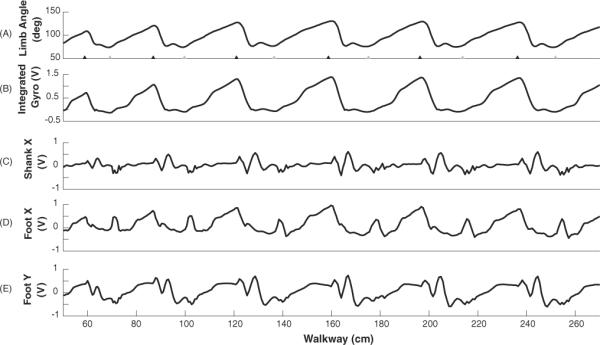
Traces of sensory signals from one trial involving the open loop controller. (A) Limb angle (vector from the hip to the metatarsophalangeal joint) obtained from video capture. Paw touchdown is shown with grey triangles and lift off is shown with black triangles. (B) Integrated gyroscope signal representing the limb angle. (C)–(E) Accelerometer signals on the shank (X direction) and the foot (X and Y directions).
Each rule in the hybrid-CPG controller improved the quality of stepping in response to environmental perturbations when compared to the open loop controller. The stance-to-swing rule influenced the amount of time each leg remained in the E3 sub-state. The swing-to-stance rule shortened the amount of time each leg remained in the F or E1 sub-states. The fatigue compensation rule in the hybrid-CPG controller increased the stimulation amplitude based on the generated GRFs in an effort to increase BW support.
3.1. Effect of stance-to-swing transition on forward over-ground walking
Walking performance varied with the hybrid-CPG controller parameters due to the changing environment (e.g. walkway resistance, muscle fatigue and choice of threshold levels in the sensory signals), thus affecting the activation of individual rules. Therefore, the effects of the sensory rules are presented through specific examples from individual trials.
A comparison of the GRF between trials with the open loop and hybrid-CPG controllers is depicted in figure 7. Using the open loop controller, the step cycle period did not adjust to the reduced friction in the centre of the walkway and the cat took longer steps that resulted in an increased backward limb extension. This backward extension also caused a decrease in supportive forces during the push-off stage of the step cycle. With the addition of the stance-to-swing transition rule in the hybrid-CPG controller, backward extension of the limb was reduced by up to 13° (figure 7(A)) while maintaining appropriate GRFs (figure 7(B)). Comparing the sum of the total forces from each leg demonstrated that without the feedback rule, load bearing support dropped to 40% of the desired load bearing level. With the transition rule in the hybrid-CPG controller, the sum of the GRFs dropped to only 80% of the desired level. While this was lower than the desired full load bearing level (12.5% of BW), it was a marked improvement over the open loop control. This rule only affected the backward extension during the stance phase of the step cycle and not flexion during the swing phase. The sensory signal used in this rule was ipsilateral foot gyroscope signal representing limb angle.
Figure 7.
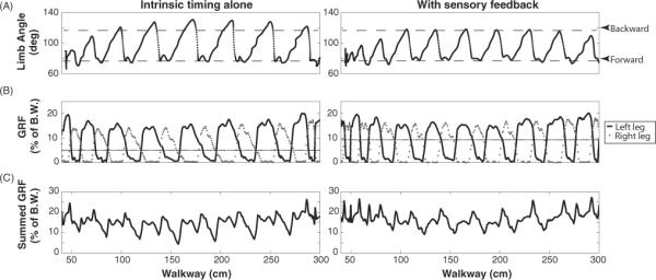
Comparison of limb excursion and GRF in trials with the open loop (left) and hybrid-CPG (right) controllers. (A) The limb angles of right leg from video capture. Increasing angle corresponds to the leg moving forward; decreasing angle corresponds to the leg moving backward. (B) GRF of right and left hind legs where the black trace represents forces from the left leg and the gray trace represents the right leg. (C) Summation of GRFs from both hind legs.
3.2. Effect of swing-to-stance transition
The swing-to-stance transition rule increased the speed of the walking cycle by eliminating excess time spent in the swing sub-states F and E1 (figure 8). With the open loop controller, the hip angle had a range of 38°, and consistently reached the end of the range of motion during flexion (figure 8(A)). Since the amount of time spent in flexion was fixed, the leg remained in swing phase (F, E1) for longer than desired. Moreover, the hip angle and timing did not adapt to the variable resistance of the walkway but instead produced movements more suitable for a uniform walkway.
Figure 8.

Effect of swing-to-stance rule on hip angle. (A) Hip angle with open loop control alone from video capture. Swing phases (F and E1) are highlighted in grey. (B) Hip angle with the addition of swing-to-stance rule truncates excess swing phase while maintaining proper hip range of motion.
With the addition of the swing-to-stance rule in the hybrid-CPG controller, a more desirable adaptation of the hip angle was achieved and the swing stage was adjusted proportionally to the walkway resistance (figure 8(B)). The range of the hip angle was slightly reduced to 35° but more importantly the E1 duration was often truncated. This is evident in figure 8(B) in the middle of the trial (around 5–10 s) during steps over the walkway where the resistance decreased. There was less time holding the limb in flexion due to the ability of the cat to move more easily across the walkway as opposed to the regions with higher resistance. The sensory signal used in this rule was the foot accelerometer signal in the Y direction of the ipsilateral hind limb (e.g. figure 6(E)).
3.3. Combined transition effects on forward over-ground walking
Stick figure representations and foot trajectories of the right hind limb portray the effect of both transition rules between the open loop and hybrid-CPG controllers (figure 9). Less time was spent in the swing portion of the step cycle in the hybrid-CPG controller than the open loop controller. The backward excursions were constrained when the stance-to-swing was activated as observed by the decreased step length (figure 9(B)). With the hybrid-CPG controller, the joint angle range of the hip slightly decreased and was more comparable to natural movements (Goslow et al 1973) when sensory feedback was enabled (table 2).
Figure 9.

Motion tracking data and foot trajectory for trials with and without sensory feedback: (A) stick figure representation of the right hind leg from video capture (direction of movement is towards the right). Black triangles mark the beginning of steps. Upper panel: with open loop control alone, regions of hyperextension are evident. Dotted stick figures show whole leg hyperextension. Lower panel: with sensory feedback the regions of hyperextension are eliminated. (B) Foot trajectories of multiple steps overlaid with respect to the hip marker from trials shown in (A). Steps are drawn with increasing darkness of grey as the trial progressed. Left panel: large backward hyperextension without sensory feedback. Right panel: sensory feedback reduces backward hyperextension.
Table 2.
Average joint angles measured during single trials with and without sensory feedback (walking at approximately 0.25 m s−1). The values were measured in degrees with the ratio of measured joint angles to typical joint angles (walking at 0.67 m s−1).
| Joint angle range (typical) | Open loop controller (ratio) | Hybrid-CPG controller (ratio) |
|---|---|---|
| Hip (49) | 27 (0.55) | 24 (0.49) |
| Knee (38) | 43 (1.1) | 39 (1.0) |
| Ankle (45) | 96 (2.1) | 68 (1.5) |
3.4. Fatigue compensation rule
Over the course of multiple trials, muscles fatigued and produced less supportive force. The sensory feedback rules of the hybrid-CPG controller compensated for this internal perturbation to the system. In figure 10, the stimulation amplitudes of the left leg remained unchanged from open loop controller amplitudes. However, in the right leg, feedback increased stimulation amplitudes in stance by a predetermined amount (30%) when force dropped below the critical threshold. This resulted in an increase in the GRF of right foot from 0.72 kg (19% of BW) to an average of 0.93 kg (25% of BW) over the next six steps. The stimulation amplitudes during the stance phase of the right leg were increased after the vertical dotted activation line on the following step.
Figure 10.

Effect of the fatigue compensation rule on force production during a single trial: (A) GRF of left hind leg and threshold for activation of the fatigue compensation rule if the supportive force drops below the threshold (grey dashed line) for a prolonged period of time. (B) Stimulation amplitudes on two different extensor electrodes (knee in black and ankle in grey) during the stance phase (E2 and E3). (C) Similar to (A) but for the right hind leg. The black, vertical dashed line shows activation of the rule due to prolonged sub-threshold force production in stance. Force increases to acceptable levels on the remaining steps. (D) Similar to (B) but stimulation amplitudes for right side extensor electrodes (knee and ankle) increase in E2 by 30% (to a maximum of 20 mA) on steps following rule activation. Only the knee extension received an increase in amplitude because maintaining appropriate posture was difficult when ankle extension was increased during the stance phase.
3.5. Summary of results
A summary of walking characteristics across the 74 successful trials (18 open loop, 56 hybrid-CPG) are presented in table 3. Peak step length, average velocity, number of steps and the summation of left and right forces (averaged over time) were determined for each trial. Step cycle duration and peak force were analysed on a step basis (i.e. all steps for all trials pooled).
Table 3.
Summary of 74 trials in which cats walked 75% of the walkway.
| Walking property | Open loop controller | Hybrid-CPG controller | P-values | |
|---|---|---|---|---|
| Trial-based | N = 18 | N = 56 | ||
| Peak step lengtha | Mean ∓ SDc | 24.9 ∓ 8.4 | 21.8 ∓ 7.5 | 0.06e |
| Average velocity | Mean ∓ SDc | 0.22 ∓ 0.04 m s−1 | 0.21 ∓ 0.05 m s−1 | 0.62e |
| Number of stepsb | Mediand(Q1,Q3) | 7 (6, 9) | 9(8, 11) | 0.024f |
| Sum of forces | Mediand(Q1,Q3) | 15.1% BW (14.3, 18.7) | 18.4% BW (16.1, 20.0) | 0.10f |
| Step-based | N = 134 | N = 544 | ||
| Step cycle durationb | Mediand(Q1,Q3) | 1.48 s (1.15, 1.49) | 1.27 s (1.15, 1.49) | <.001f |
| Peak step force | Mediand(Q1,Q3) | 17.1% BW (14.7, 20.3) | 17.0% BW (14.8, 20.1) | 0.69f |
| Successful steps | (%) (success/total) | 49% (65/134) | 68% (372/544) |
Step length was normalized against the distance from the ankle to the metacarpophalangeal joint.
Significant difference between trials with open loop control alone and with combined open and closed loop control.
The means and SD are shown for normally distributed data.
The medians and first and third quartiles (Q1,Q3) are shown for non-normally distributed data.
Unpaired student's t-test was used for normally distributed data.
Independent samples median test (non-parametric) was used for non-normally distributed data.
BW = Body weight.
The mean (± SD) normalized peak step length was 3.1 units smaller with the hybrid-CPG controller (21.8 ± 7.5, N = 56) than with the open loop controller (24.9 ± 8.4, N = 18). However, t-test showed that the difference was not significant (P = 0.06). The t-test was appropriate as the Lilliefors test scores for normality were 0.34 and 0.09 respectively for the hybrid-CPG and open loop controller, and the group variances were equal (Levene's Test P = 0.62).
A nonparametric independent samples median test showed that the hybrid-CPG controller produced significantly (P = 0.024) more steps for walking the same distance: median (first quartile, third quartile) for the number of steps taken by the open loop and hybrid-CPG controllers was respectively 7 (6, 9) and 9 (8, 11). The median total supportive force showed an upward trend from the open loop controller generating 15.1% BW (14.3, 18.7) to 18.4% BW (16.1, 20.0) with the hybrid-CPG controller; however it was not significant (P = 0.10).
A difference between controllers was also observed in the step cycle duration. The median (first quartile, third quartile) for step cycle duration was significantly lower (P < 0.001, independent samples median test) with the hybrid-CPG controller (1.27 s (1.15, 1.49), N = 544 steps) than with the open loop controller (1.48 s (1.48, 1.49), N = 134 steps). Thus with the hybrid-CPG controller the cat walked with shorter step cycle durations but took a higher number of steps. Despite the additional steps taken with sensory feedback, a t-test showed that the average velocity (0.21 ± 0.05 m s−1, N = 56, Lilliefors test P > 0.5) was not significantly different (P = 0.62, equal variances assumed (Levene's Test P = 0.2)) from that obtained during the open loop condition (0.22 ± 0.04 m s−1, N = 18, Lilliefors test P = 0.107).
An independent samples median test did not reveal significant differences between the peak step forces generated by open and hybrid-CPG controllers, respectively (17.1% (14.7, 20.3) and 16.8% (14.8, 20.1) BW (P = 0.69)). When evaluating each step based on our success criteria (peak force during stance > 12.5% BW and peak step length <20 cm), 49% of open loop steps (65/134) generated adequate force (≥12.5% BW) and had a natural step length (≤20 cm) while 68% of the hybrid-CPG controller steps were successful (372/544). Periods of double stance were maintained through an overlap of 124 ms between the stance and push-off states of the two hind limbs. This overlap allowed the stance limb to build enough supportive force before the extended limb swung forward. Also, the state-based control algorithm prevented combinations of sub-states that would produce dangerous walking in either controller, such as a state of simultaneous flexion (F) in both legs that would result in falling.
4. Discussion
The goal of this study was to develop a physiologically based control algorithm capable of using open loop and closed loop control of multiple joints in the lower extremities for producing locomotion. Emulating the biological CPG provides a control solution for bipedal walking that is thought to be the most efficient method to date (Collins et al 2005, Berniker et al 2009). The controller emulated the functionality of the spinal CPG by processing intrinsic and sensory-based information to implement detailed descriptions of the walking cycle. The feedback information from external sensors (gyroscopes, accelerometers, force plates) was processed to adjust stimulation amplitudes similar to how the biological CPG adjusts muscle activation during locomotion based on sensory neural signals. The controller adapted the stimulation patterns in response to internal and external perturbations to maintain body support and produce effective over-ground locomotion. In agreement with earlier evidence presented by Guevremont et al (2007), the combination of open loop and closed loop control provided the most functional over-ground walking and the most successful steps. Throughout the regions of least resistance in the walkway, the sensory rules allowed the state transitions in the hybrid-CPG controller to increase the speed of walking, resulting in decreased step length and preventing excessive extension and loss of load bearing GRFs. Load bearing is a critical measure of safety for a functional walking device as it prevents falling and reduces the dependence on the arms for weight support.
The use of appropriate sensory signals was essential for successful implementation of feedback rules in the hybrid-CPG controller. The gyroscopes were most suited for the stance-to-swing transition rule because they best represented the relative magnitudes and timing information of the limb angle. The main challenge with the gyroscope signals was the drift caused by the integration. Therefore, the signal had to be reset at the onset of every stance phase. More sophisticated methodologies for obtaining limb angle using a combination of accelerometer and gyroscope feedback have been proposed (Dejnabadi et al 2006). For our purposes, we found that a simple reset worked sufficiently well to control walking.
Each of the sensor types used in this study could be practically translated to future applications. The force plates in the walkway can be replaced by force sensitive resistors in each shoe. This has proven to be a reliable and inexpensive solution in many commercial devices such as the Ness L300 (Bioness, Valencia, CA, USA) and the Odstock dropped foot stimulator (Salisbury District Hospital, UK). Other sensory information required by the controller can be provided by a combination of a gyroscope and an accelerometer. Currently, sensor technology is small and readily available (Analog Devices, Norwood, MA, USA).
Previous work has focused on developing a controller capable of walking on a treadmill (Strange and Hoffer 1999), or stepping in place (Saigal et al 2004). When stepping in place, Saigal et al (2004) found that locomotion driven by FES control using open loop or closed loop control alone was equally successful. However, when the animal must physically propel itself, many new challenges are introduced. The FES generated movements have to produce enough force to propel the animal forward as it ambulates and unstable controller states become of paramount importance. In order to create a functional device that can be eventually translated to the clinic, the control algorithm had to be tested in the demanding environment of over-ground walking.
In a clinical application, the device will have to maintain safe walking with a variety of conditions. In order to do so, the controller should adapt to perturbations using sensory feedback similar to the ways in which the human body relies on sensory input (Rossignol et al 2006). The walkway used in the present experiments had a variable friction profile that perturbed the operation of the controller. The varying resistance was analogous to walking over variable pitched terrain. During regions of low friction, the cart and cat would have momentum similar to walking downhill. The controller responded by increasing the step frequency (by truncating excess extension and flexion) of the walking to maintain supportive forces.
The hybrid-CPG controller also had to respond to variations in muscle output. Direct activation of the muscles with electrical stimulation has been known to produce rapid fatigue of the activated muscles (Bogey and Hornby 2007). As muscles fatigue, the preset stimulation amplitudes would no longer suffice. The fatigue compensation rule in this study recognized a gradual decrease in muscle strength over a prolonged period of time and increased stimulation amplitudes to compensate and maintain force production. The fatigue rule was limited by maximal safe stimulation amplitudes. However, this solution did not address differential fatigue where different muscles fatigue at different rates and cause much larger disruptions in a control system (Godfrey et al 2002). Eventually, the experiments were terminated when safe stimulation limits were reached without producing adequate force. Alternative stimulation methods such as intraspinal microstimulation (ISMS) are more fatigue resistant and require a less demanding fatigue compensation rule (Lau et al 2007).
The swing-to-stance transition was designed to limit excess time spent in the swing phase to optimize the walking cycle. The rule activates if the leg adequately reaches its range of flexion, thereby eliminating excess swing time and speeding up the walking cycle. As a secondary benefit, the truncated swing phase allowed for more time in contact with the ground and more force overlap between limbs.
The implemented hybrid-CPG controller does have some limitations in its present configuration. Currently, the IF-THEN rule thresholds are set manually by the operator. Incorrect threshold levels can cause the controller to become unstable (often by inappropriately activating rules if the thresholds are prematurely reached). If thresholds are set too leniently, rules never activate compromising the safety and the adaptability of the controller. Moreover, the fatigue compensation rule would prove more effective if adaptive stimulation amplitudes were used across all sub-states rather than only the E2 sub-state as currently implemented. In addition, the effectiveness of the limb angle calculations could be improved through more accurate corrections for high frequency noise (accelerometers) and drift (gyroscopes) in the signals. The controller utilizes a single sensory signal as input to a rule. More complex rules utilizing multiple signals would better emulate the natural control of walking. Nonetheless, the general design of the locomotion control algorithm provides the capabilities to perform these corrections with relative ease through the inclusion of additional states and sensory transitions. By adapting the controller to different stimulation modalities and new sensory inputs, the algorithm could improve walking in a variety of applications.
5. Conclusions and future work
The work presented here demonstrates our ability to create a reconfigurable control algorithm for realizing different stimulation paradigms to create functional walking movements in multiple joints. The implemented hybrid-CPG controller was capable of adapting to different environmental perturbations while maintaining sufficient GRF to support the BW of the animal. Through the in vivo over-ground walking trials, the combination of open and closed loop control produced the most effective walking and most successful steps.
For the next stage in development, we will implement the software algorithm in a hardware-based model using mixed signal VLSI circuitry. The chip will be tested in vivo and the results will be compared to those obtained by the software controller. The silicone controller will be flexible enough to allow additional rules and utilize a variety of input and output stages. Moreover, the output will be capable of driving other modalities of FES. Specifically, we will replace IMS with ISMS and external sensors with recordings from the dorsal root ganglia to allow the internalization of the prosthetic device. Eventually, we hope to develop a compact and fully implantable walking prosthesis.
Acknowledgments
This work was funded in part by the Alberta Heritage Foundation for Medical Research (AHFMR), the Canadian Institutes of Health Research and the National Institute of Health. VKM is an AHFMR Senior Scholar.
References
- Archambault PS, Deliagina TG, Orlovsky GN. Non-undulatory locomotion in the lamprey. Neuroreport. 2001;12:1803–7. doi: 10.1097/00001756-200107030-00009. [DOI] [PubMed] [Google Scholar]
- Berniker M, Jarc A, Bizzi E, Tresch MC. Simplified and effective motor control based on muscle synergies to exploit musculoskeletal dynamics. Proc. Natl Acad. Sci. USA. 2009;106:7601–6. doi: 10.1073/pnas.0901512106. [DOI] [PMC free article] [PubMed] [Google Scholar]
- Bogey R, Hornby GT. Gait training strategies utilized in poststroke rehabilitation: are we really making a difference? Top. Stroke Rehabil. 2007;14:1–8. doi: 10.1310/tsr1406-1. [DOI] [PubMed] [Google Scholar]
- Brown TG. On the nature of the fundamental activity of the nervous centres; together with an analysis of the conditioning of rhythmic activity in progression, and a theory of the evolution of function in the nervous system. J. Physiol. 1914;48:18–46. doi: 10.1113/jphysiol.1914.sp001646. [DOI] [PMC free article] [PubMed] [Google Scholar]
- Burke RE, Degtyarenko AM, Simon ES. Patterns of locomotor drive to motoneurons and last-order interneurons: clues to the structure of the CPG. J. Neurophysiol. 2001;86:447–62. doi: 10.1152/jn.2001.86.1.447. [DOI] [PubMed] [Google Scholar]
- Collins S, Ruina A, Tedrake R, Wisse M. Efficient bipedal robots based on passive-dynamic walkers. Science. 2005;307:1082–5. doi: 10.1126/science.1107799. [DOI] [PubMed] [Google Scholar]
- Conway BA, Hultborn H, Kiehn O. Proprioceptive input resets central locomotor rhythm in the spinal cat. Exp. Brain Res. 1987;68:643–56. doi: 10.1007/BF00249807. [DOI] [PubMed] [Google Scholar]
- Crago PE, Lan N, Veltink PH, Abbas JJ, Kantor C. New control strategies for neuroprosthetic systems. J. Rehabil. Res. Dev. 1996;33:158–72. [PubMed] [Google Scholar]
- Dejnabadi H, Jolles BM, Casanova E, Fua P, Aminian K. Estimation and visualization of sagittal kinematics of lower limbs orientation using body-fixed sensors. IEEE Trans. Biomed. Eng. 2006;53:1385–93. doi: 10.1109/TBME.2006.873678. [DOI] [PubMed] [Google Scholar]
- Dick TE, Oku Y, Romaniuk JR, Cherniack NS. Interaction between central pattern generators for breathing and swallowing in the cat. J. Physiol. 1993;465:715–30. doi: 10.1113/jphysiol.1993.sp019702. [DOI] [PMC free article] [PubMed] [Google Scholar]
- Ekeberg O, Pearson K. Computer simulation of stepping in the hind legs of the cat: an examination of mechanisms regulating the stance-to-swing transition. J. Neurophysiol. 2005;94:4256–68. doi: 10.1152/jn.00065.2005. [DOI] [PubMed] [Google Scholar]
- Godfrey S, Butler JE, Griffin L, Thomas CK. Differential fatigue of paralyzed thenar muscles by stimuli of different intensities. Muscle Nerve. 2002;26:122–31. doi: 10.1002/mus.10173. [DOI] [PubMed] [Google Scholar]
- Goslow GE, Reinking RM, Stuart DG. The cat step cycle: hind limb joint angles and muscle lengths during unrestrained locomotion. J. Morphol. 1973;141:1–41. doi: 10.1002/jmor.1051410102. [DOI] [PubMed] [Google Scholar]
- Grillner S. Neurobiological bases of rhythmic motor acts in vertebrates. Science. 1985;228:143–9. doi: 10.1126/science.3975635. [DOI] [PubMed] [Google Scholar]
- Grillner S, Matsushima T. The neural network underlying locomotion in lamprey—synaptic and cellular mechanisms. Neuron. 1991;7:1–15. doi: 10.1016/0896-6273(91)90069-c. [DOI] [PubMed] [Google Scholar]
- Grillner S, Zangger P. On the central generation of locomotion in the low spinal cat. Exp. Brain Res. 1979;34:241–61. doi: 10.1007/BF00235671. [DOI] [PubMed] [Google Scholar]
- Guevremont L, Norton JA, Mushahwar VK. Physiologically based controller for generating overground locomotion using functional electrical stimulation. J. Neurophysiol. 2007;97:2499–510. doi: 10.1152/jn.01177.2006. [DOI] [PubMed] [Google Scholar]
- Halbertsma JM. The stride cycle of the cat: the modelling of locomotion by computerized analysis of automatic recordings. Acta Physiol. Scand. Suppl. 1983;521:1–75. [PubMed] [Google Scholar]
- Hiebert GW, Pearson KG. Contribution of sensory feedback to the generation of extensor activity during walking in the decerebrate cat. J. Neurophysiol. 1999;81:758–70. doi: 10.1152/jn.1999.81.2.758. [DOI] [PubMed] [Google Scholar]
- Hultborn H, Nielsen JB. Spinal control of locomotion—from cat to man. Acta Physiol. 2007;189:111–21. doi: 10.1111/j.1748-1716.2006.01651.x. [DOI] [PubMed] [Google Scholar]
- Islam SS, Zelenin PV, Orlovsky GN, Grillner S, Deliagina TG. Pattern of motor coordination underlying backward swimming in the lamprey. J. Neurophysiol. 2006;96:451–60. doi: 10.1152/jn.01277.2005. [DOI] [PubMed] [Google Scholar]
- Kiehn O. Locomotor circuits in the mammalian spinal cord. Annu. Rev. Neurosci. 2006;29:279–306. doi: 10.1146/annurev.neuro.29.051605.112910. [DOI] [PubMed] [Google Scholar]
- Kobetic R, Triolo RJ, Marsolais EB. Muscle selection and walking performance of multichannel FES systems for ambulation in paraplegia. IEEE Trans. Rehabil. Eng. 1997;5:23–9. doi: 10.1109/86.559346. [DOI] [PubMed] [Google Scholar]
- Lau B, Guevremont L, Mushahwar VK. Strategies for generating prolonged functional standing using intramuscular stimulation or intraspinal microstimulation. IEEE Trans. Neural Syst. Rehabil. Eng. 2007;15:273–85. doi: 10.1109/TNSRE.2007.897030. [DOI] [PubMed] [Google Scholar]
- Mazurek K, Holinski BJ, Everaert DG, Stein RB, Mushahwar VK, Etienne-Cummings R. Locomotion processing unit. Proc. IEEE Biomedical Circuits and Systems Conf. (BIOCAS) (Paphos, Cyprus).2010. pp. 286–9. [Google Scholar]
- Mazurek KA, Etienne-Cummings R. Implementation of functional components of the locomotion processing unit. Proc. IEEE Biomedical Circuits and Systems Conf. (BIOCAS) (San Diego, CA, USA).2011. pp. 21–4. [Google Scholar]
- McCrea DA, Rybak IA. Modeling the mammalian locomotor CPG: insights from mistakes and perturbations. Prog. Brain Res. 2007;165:235–53. doi: 10.1016/S0079-6123(06)65015-2. [DOI] [PMC free article] [PubMed] [Google Scholar]
- McCrea DA, Rybak IA. Organization of mammalian locomotor rhythm and pattern generation. Brain Res. Rev. 2008;57:134–46. doi: 10.1016/j.brainresrev.2007.08.006. [DOI] [PMC free article] [PubMed] [Google Scholar]
- Mealy GH. A method for synthesizing sequential circuits. AT&T Tech. J. 1955;34:1045–79. [Google Scholar]
- Mentel T, Krause A, Pabst M, El Manira A, Buschges A. Activity of fin muscles and fin motoneurons during swimming motor pattern in the lamprey. Eur. J. Neurosci. 2006;23:2012–26. doi: 10.1111/j.1460-9568.2006.04738.x. [DOI] [PubMed] [Google Scholar]
- Nilsson J, Thorstensson A, Halbertsma J. Changes in leg movements and muscle activity with speed of locomotion and mode of progression in humans. Acta Physiol. Scand. 1985;123:457–75. doi: 10.1111/j.1748-1716.1985.tb07612.x. [DOI] [PubMed] [Google Scholar]
- Prilutsky BI, Herzog W, Allinger TL. Mechanical power and work of cat soleus, gastrocnemius and plantaris muscles during locomotion: possible functional significance of muscle design and force patterns. J. Exp. Biol. 1996;199:801–14. doi: 10.1242/jeb.199.4.801. [DOI] [PubMed] [Google Scholar]
- Prochazka A, Gritsenko V, Yakovenko S. Sensory control of locomotion: reflexes versus higher-level control. Adv. Exp. Med. Biol. 2002;508:357–67. doi: 10.1007/978-1-4615-0713-0_41. [DOI] [PubMed] [Google Scholar]
- Quintero HA, Farris RJ, Durfee WK, Goldfarb M. Feasibility of a hybrid-FES system for gait restoration in paraplegics. 2010 Annual Int. Conf. of the IEEE Engineering in Medicine and Biology Society (EMBC); 2010. pp. 483–6. [DOI] [PMC free article] [PubMed] [Google Scholar]
- Rossignol S, Dubuc R, Gossard JP. Dynamic sensorimotor interactions in locomotion. Physiol. Rev. 2006;86:89–154. doi: 10.1152/physrev.00028.2005. [DOI] [PubMed] [Google Scholar]
- Saigal R, Renzi C, Mushahwar VK. Intraspinal microstimulation generates functional movements after spinal-cord injury. IEEE Trans. Neural Syst. Rehabil. Eng. 2004;12:430–40. doi: 10.1109/TNSRE.2004.837754. [DOI] [PubMed] [Google Scholar]
- Strange KD, Hoffer JA. Restoration of use of paralyzed limb muscles using sensory nerve signals for state control of FES-assisted walking. IEEE Trans. Rehabil. Eng. 1999;7:289–300. doi: 10.1109/86.788466. [DOI] [PubMed] [Google Scholar]
- Sweeney PC, Lyons GM, Veltink PH. Finite state control of functional electrical stimulation for the rehabilitation of gait. Med. Biol. Eng. Comput. 2000;38:121–6. doi: 10.1007/BF02344765. [DOI] [PubMed] [Google Scholar]
- Thrasher TA, Popovic MR. Functional electrical stimulation of walking: function, exercise and rehabilitation. Ann. Readapt. Med. Phys. 2008;51:452–60. doi: 10.1016/j.annrmp.2008.05.006. [DOI] [PubMed] [Google Scholar]
- Tomovic R, Mcghee RB. A finite state approach to synthesis of bioengineering control systems. IEEE Trans. Hum. Factors Electron. 1966;7:65–9. [Google Scholar]
- Vogelstein RJ, Tenore FVG, Guevremont L, Etienne-Cummings R, Mushahwar VK. A silicon central pattern generator controls locomotion in vivo. IEEE Trans. Biomed. Circuits Syst. 2008;2:212–22. doi: 10.1109/TBCAS.2008.2001867. [DOI] [PubMed] [Google Scholar]
- Yakovenko S. A hierarchical perspective on rhythm generation for locomotor control. Prog. Brain Res. 2011;188:151–66. doi: 10.1016/B978-0-444-53825-3.00015-2. [DOI] [PubMed] [Google Scholar]
- Yamaguchi T. The central pattern generator for forelimb locomotion in the cat. Prog. Brain Res. 2004;143:115–22. doi: 10.1016/S0079-6123(03)43011-2. [DOI] [PubMed] [Google Scholar]
- Yang JF, Winter DA. Surface EMG profiles during different walking cadences in humans. Electroencephalogr. Clin. Neurophysiol. 1985;60:485–91. doi: 10.1016/0013-4694(85)91108-3. [DOI] [PubMed] [Google Scholar]