

Abstract
Biofilms are layers of microbial cells growing on an interface and they can form highly complex structures adapted to a wide variety of environmental conditions. Biofilm streamers have a small immobile base attached to the support and a flexible tail elongated in the flow direction, which can vibrate in fast flows. Herein we report numerical results for the role of the periodical movement of biofilm streamers on the nutrient uptake and in general on the solute mass transfer enhancement due to flow-induced oscillations. We developed what to our knowledge is a novel two-dimensional fluid-structure interaction model coupled to unsteady solute mass transport and solved the model using the finite element method with a moving mesh. Results demonstrate that the oscillatory movement of the biofilm tail significantly increases the substrate uptake. The mass transfer coefficient is the highest in regions close to the streamer tip. The reason for substrate transfer enhancement is the increase in speed of tip movement relative to the surrounding liquid, thereby reducing the thickness of the mass transfer boundary layer. In addition, we show that the relative mass transfer enhancement in unsteady conditions compared with the rigid static structure is larger at higher flow velocities, and this relative increase favors a more flexible structure.
Introduction
Biofilms are natural structures formed by microbial communities encapsulated inside a matrix of self-secreted extracellular polymeric substances, growing attached most commonly to a solid surface. Biofilm cells can get their nutrients either from the bulk liquid or from the support material on which they grow attached. When the soluble nutrients (called substrates) are provided by the liquid, a transport chain forms from the bulk liquid to the biofilm cells. Although in the bulk flow, convection is the dominant transport mechanism for substrates, around the biofilm surface a mass transfer boundary layer develops in which diffusion dominates. Diffusion is by far the main transport mechanism of solutes to/from microbial cells also in the biofilm because the gel-like biofilm matrix largely prevents convection.
In terms of mass transfer, a fast fluid flow can be beneficial to microbial inhabitants of biofilms as it will assure more solute transport through a thinner boundary layer, thus providing better solute exchange between biofilm and bulk liquid. However, faster flows also exert larger forces on the biofilm, which lead to larger stresses in the biofilm structure and eventually to biomass detachment. One way biofilms cope with these stresses, similar to sessile marine organisms (1), is by developing (visco-)elastic flexible bodies, easily deformable under forces exerted upon them by the flow. Biofilm streamers are one of the complex microbial architectures that are believed to employ the viscoelastic material properties to their benefit. Streamers are structures consisting of a base attached to the support substratum and a tail elongated in the flow direction, which reconfigures itself by lateral movement in the flow parallel to the substratum (2). It has been initially reported that biofilm streamers can grow preferably in flow-cells under turbulent hydrodynamic conditions (2) and in extreme acidic environments (3). Biofilm streamers are therefore commonly observed in rivers (4), where the flow is generally turbulent. However, there are reports of streamers developed behind spacer filaments from the feed channels of reverse osmosis membrane devices (5), supposedly operated in laminar but unsteady flow conditions. Recently, Rusconi et al. (6) also reported the formation of filamentous streamers in microfluidic devices under laminar flow conditions, and showed that formation of threadlike streamers is proportional to the intensity of the secondary flow around the corners in their microfluidic setup (7).
Stoodley et al. (2) grew mixed population biofilms in a flow cell under turbulent flow conditions and observed that the biofilm structures had a streamlined profile elongated along the flow. Streamers oscillated laterally at the high flow velocities with characteristic frequencies. In an initial computational study on flow-induced periodical streamer movement, we confirmed that vortex shedding from the streamer head is the main cause of the oscillations (8). More importantly, we have also suggested that the streamlined shape helps the elongated biofilm structures to reduce the fluid drag significantly, thereby reducing the detachment risk.
In addition to the flow conditions, nutrient availability also plays a significant role in shaping the biofilm structure. Stoodley et al. (9) reported that at high shear rates the existence and the thickness of biofilm streamers were related to the nutrient availability. The distinguishable streamer structures and ripples developed at low substrate concentrations, whereas in more concentrated substrate environments they overgrew and merged to form heterogeneous porous structures thus shadowing the influence of liquid shear.
On the engineering side, it has been reported that substrate transfer rate can be increased by irregularly shaped or filamentous biofilms (10,11). As a result of these studies, it has been proposed that the increased mass transfer is caused by biofilm protuberances penetrating outside the boundary layer into the convection-dominated bulk fluid (10–13). However, if the biofilm structure is rigid (i.e., not allowing oscillatory movement) theoretical models both in two dimensions (14) and three dimensions (15) clearly showed that, by contrast, a decrease in mass transfer will be expected in immobile fingerlike, dendritic, or mushroom-like biofilm structures compared to planar and smooth biofilms. Therefore, it has been hypothesized that the periodic movement of elastic biofilm structures induced by the flow may be the real cause of increased mass transfer in fingerlike or streamer biofilms.
In our previous work, we suggested that, from a mechanical point of view, the streamlined form of biofilms is an advantage for their survival (8). In this work, we look at the significance of this flexible form and hence the resulting oscillatory movement from the nutrient mass transfer and biological points of view. Specifically, we evaluate by numerical simulations how significantly the periodic movement of streamers increases the substrate uptake into the biofilm by enhancing the micromixing in the fluid close to the biofilm surface.
Because, to our knowledge, the problem of coupled fluid-flexible structure interaction with unsteady mass transfer has not been studied before, the first aim of this article is to introduce in detail the newly developed computational methods. As our second aim, we characterized quantitatively the increase of mass transfer coefficients for the oscillating biofilm relative to a rigid immobile structure. From the multiple factors that may influence the magnitude of mass transfer to the moving body, we studied here the dependency of mass transfer coefficients on 1), liquid velocity and 2), biofilm flexibility.
Model Description
Many physical, chemical, and biological processes act simultaneously in biofilms with orders-of-magnitude difference in time- and spatial scales. The biofilm is, for example, exposed to different forces by the liquid flow, internal mechanical stress develops leading to deformations and eventually to biofilm detachment, solutes are transported by convection and diffusion, solutes are converted in multiple reactions with very different rates, and then microbial cells can grow, divide, and be transported in the biofilm, while extracellular polymers are excreted. This model assumes only the very fast processes with relaxation times in the order of seconds or less (16), characteristic for a relatively thin biofilm streamer (∼100 μm). Therefore, although the very fast fluid dynamics, biofilm deformations, and substrate transport with reaction are calculated from time-dependent equations, the slow biofilm development processes are ignored and the biofilm neither grows nor do biomass patches detach.
The force that the biofilm streamer experiences in the flow direction is called “drag” and the perpendicular one is the “lift”. These forces deform the flexible structure and in return the structure also changes the flow conditions, because the walls bounding the fluid domain are moving. This fluid-structure interaction is modeled by coupling the Navier-Stokes equations of fluid motion with the structural dynamics of the biofilm and solving the equations simultaneously. In nature, biofilms behave as viscoelastic materials (17) (i.e., they show elastic solidlike response in short timescales and viscous fluidlike response in long timescales). However, due to the very small timescales studied in this work (<2 s), we assume an elastic material model for the biofilm streamers. Further, the mass transfer is modeled by solving the dynamic convection-diffusion-reaction equations using the actual flow velocities calculated from Navier-Stokes equations. The arbitrary Lagrangian-Eulerian (ALE) formulation for fluid domain is employed to account for the mutual deformation of fluid and solid at their interface (8). The following sections will describe the model details and its numerical implementation.
Model domain
The two-dimensional biofilm streamer shown in Fig. 1, with geometrical and mechanical specifications analogous to Taherzadeh et al. (8), is subjected to a range of flow conditions similar to those considered in the experimental settings of Stoodley et al. (2). The model streamer dimensions are also similar to the natural one studied in Stoodley et al. (2).
Figure 1.
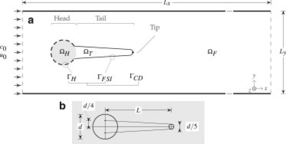
(a) Schematic representation of the two-dimensional subdomains and boundary conditions: ΩH, biofilm head subdomain; ΩT, biofilm streamer tail subdomain; ΩF, fluid subdomain; Γ, interface between biofilm and fluid. At the inlet boundary c0 is the constant substrate concentration and u0 is the fluid velocity. The center of ΩH is located at x = y = 1.5 × 10⁻³ m. (b) Geometric construction of the biofilm streamer.
We considered this two-dimensional model simplification because an accurate solution of the equivalent three-dimensional problem is intractable with our current computational resources. Nevertheless, we believe that the obtained two-dimensional results also provided very significant insight and could guide the development of much more computationally intensive three-dimensional models in future. The flow domain is a rectangular channel, with length Lx in the main stream direction, x, and width Ly in the side-stream direction, y (Fig. 1).
Depending on the physics equations solved, the computational domain is partitioned in a few subdomains, in which different sets of equations are applied. For the fluid-structure interaction, the domain consists of three nonoverlapping computational subdomains: the circular biofilm colony head ΩH, the biofilm streamer tail ΩT, and the fluid ΩF. The whole biofilm domain is the union ΩB = ΩH ∪ ΩT. We define the fluid-structure interaction interface as ΓFSI = ΩF ∩ ΩT because only the biofilm tail is mobile. Because the whole biofilm consumes soluble substrate, the mass flux continuity interface is ΓCD = ΩF ∩ ΩB = ΓH ∪ ΓFSI (with ΓH the head surface). The parameters used in this article are listed in Table 1.
Table 1.
Model parameters
| Parameter | Symbol | Value |
|---|---|---|
| Fluid-structure interaction | ||
| Liquid density∗ | ρF | 1000 kg · m−3 |
| Liquid dynamic viscosity∗ | μF | 10−3kg · m−1 · s−1 |
| Biofilm density† | ρB | 1000 kg · m−3 |
| Biofilm Young's modulus‡ | EB | 1000 and 4000 kg · m−1 · s−2 |
| Biofilm Poisson's ratio§ | νB | 0.4 |
| Mass transfer with reaction | ||
| Substrate diffusion coefficient¶ | D | 2.5 × 10⁻⁹ m2 · s−1 |
| Substrate uptake rate coefficient‖ | k | 0.03 mol·m−3 · s−1 |
| Substrate saturation coefficient∗∗ | K | 0.003 mol · m−3 |
| System properties | ||
| Domain length | Lx | 1.2 × 10⁻² m |
| Domain height | Ly | 3 × 10⁻³ m |
| Streamer head diameter†† | d | 3.33 × 10⁻⁴ m |
| Streamer tail length†† | L | 4.5 × d |
| Inlet substrate concentration‡‡ | c0 | 0.025 mol · m−3 |
| Inlet fluid velocity†† | u0 | 0.1,0.15,…,0.45 m s−1 corresponding to Re = 33,50,…,150 |
Water, 20°C.
Assumed close to water because biofilms consist of >90% water.
This is a function of flow velocity and biofilm flexibility; see Mass Transfer Enhancement in the main text.
Assumed close to rubber.
Dissolved oxygen in water at 20°C.
Assumed for oxygen uptake by heterotrophic microorganisms (Henze (30)), with a microbial concentration in the biofilm of 20 g · L−1.
Affinity of heterotrophic microorganisms for oxygen (Henze (30)).
Estimated from Stoodley et al. (2).
Relatively low dissolved substrate concentration, here 10% of oxygen saturation in water in contact with air.
Fluid-structure interaction
The formulation of fluid-structure interaction (FSI) model is described in detail in Taherzadeh et al. (8). Section S1 in the Supporting Material presents all model equations used in this study in dimensional and nondimensional form, together with the resulting dimensionless groups and a table of notations. The liquid flow (here water) in subdomain ΩF is governed by the laminar incompressible Navier-Stokes equations with time-dependent momentum conservation and continuity equations. An ALE convective velocity (u – uG) is defined for the relative velocity of the fluid flow inside a moving mesh. The inlet flow boundary (at x = 0) is defined as a uniform velocity profile with horizontal velocity component ux = u0 and transverse velocity component uy = 0. Slip conditions are applied to the upper and lower domain walls, at y = 0 and y = Ly. At the outflow (x = Lx), the zero pressure and no viscous forces boundary condition is applied. A no-slip condition is imposed on the circular base of the streamer.
The structural deformations of the biofilm streamer are obtained using an isotropic elastic material model including geometrically nonlinear formulation to allow for large structural deformations (8). The nonlinear elastodynamics equation is applied for the biofilm, formulated in a Lagrangian frame of reference. Because the streamer position changes in time, the finite element mesh will be continuously deformed. Fixed constraints are applied to ΩH whereas ΩT is free to move. ΓFSI is the boundary where the effective coupling of fluid-structure interaction is enforced (Fig. 1) so that the fluid at ΓFSI moves with the same velocity as the walls of the biofilm structure. In addition, the dynamic continuity of stresses also applies on ΓFSI. At all other boundaries of the domain, the mesh movement is set to zero in all directions.
The transient solution of the FSI submodel describes the unsteady liquid flow and the movement of the biofilm streamer boundaries in time. The FSI model provides the basis for the unsteady solute mass transfer submodel presented in the following section.
Mass transfer
The mass transfer model couples the convection-diffusion transport of solute in the liquid subdomain ΩF, solved on moving mesh frame (spatial coordinates, χ), and the diffusion-reaction solute mass balance in the biofilm subdomain ΩB, solved on material coordinate frame (fixed coordinates, X) to minimize the numerical interference of the stabilization algorithm (See section Model-solution in the current article).
Assuming transport of diluted chemical species through diffusion and convection in the fluid subdomain, the mass balance equation on ΩF states
| (1) |
where c is the solute (here substrate) concentration, D is the diffusion coefficient, u is the liquid velocity field vector, and uG is the moving mesh velocity. The velocity term u is obtained from the solution of Navier-Stokes equations and uG from the solution of ALE equations, both solved in the FSI submodel (see Taherzadeh et al. (8) for details).
In the biofilm subdomain ΩB the diffusion-reaction equation reads:
| (2) |
The substrate consumption (reaction rate R) is assumed to follow a simple Monod kinetics,
| (3) |
where k is the reaction rate constant and K is the half-saturation concentration of substrate. Certainly, other reaction schemes and rates as well as multiple solute components can be easily included to describe more complex systems. We also assumed here for simplicity of the model analysis that the diffusion coefficient in biofilm is equal to that in the liquid. This choice was based on preliminary model runs that showed only minor changes in mass transfer parameters when the diffusion coefficient in the biofilm was decreased to half of the value in bulk liquid, as it is usually measured for small size molecules (see Section S2 in the Supporting Material).
The inlet boundary is set to c = c0 assuming a constant substrate inlet concentration. The outlet boundary imposes a zero diffusion flux, assuming that convection is the dominating process carrying the substrate outside the domain, so that n · (D∇c) = 0. On the ΓCD boundary continuity conditions were set both for concentrations and also for fluxes. The rest of the boundaries are insulated so that there is no flux of solute (no-flux boundary condition).
In this study, the time-dependent calculations were started from the converged steady-state solutions of flow field and substrate concentration in the immobile biofilm configuration (Fig. 1).
Mass transfer enhancement and dimensionless numbers
By scaling each dimensional quantity with some characteristic value, dimensionless model equations can be obtained (see Section S1 in the Supporting Material). Space can be scaled with a characteristic length L0 (here defined as the biofilm head diameter d) and time with a conveniently chosen characteristic time t0 (e.g., the inverse of a streamer characteristic vibration frequency). In addition, velocities, displacement, stresses, and concentrations are scaled with the inlet flow velocity u0, characteristic length L0, Young modulus EB, and inlet solute concentration c0, respectively. The pressure is made dimensionless on the viscous scale. The following dimensionless numbers will therefore govern the mass transfer-fluid structure-interaction problem:
Re = L0u0ρF/μF (Reynolds),
St = L0/t0u0 (Strouhal),
Q = u0μF/EBL0 (FSI number),
τ2E = ρBL20/EBt20 = St2 Re (ρF/ρB)Q (FSI timescale, squared),
Pe = u0L0/D (Péclet),
Φ2 = kL20/Dc0 (Thiele),
M = K/c0 (dimensionless Monod number), and
τD = L20/Dt0 = St Pe (mass transport timescale).
To quantify the mass transfer enhancement of oscillating biofilms, the dimensionless Sherwood number (Sh) is used. The local Sherwood number Sh is calculated in each point at the biofilm surface ΓCD as (18)
| (4) |
where km is the local external mass transfer coefficient, c is the local concentration of solute, c0 is the concentration of solute far away from the biofilm (here equal to the inlet concentration), and n is the normal direction to the biofilm surface. Within the finite element model solution, the gradient of concentration normal to the biofilm surface was calculated from the value of net local solute flux j at the interface ΓCD:
| (5) |
To compare the mass transfer in different system configurations, a spatially averaged Sherwood number, , is calculated around the perimeter of the whole biofilm structure (ΓCD),
| (6) |
where is the spatially averaged external mass transfer coefficient, and ds is the differential length on the streamer-liquid interface ΓCD. In the same way, an average can be calculated for the tail section only (ΓFSI).
The mass transfer enhancement is expressed by the relative increase of in the oscillating streamer case (transient calculations), when a quasi-steady state has been reached (denoted by ) relative to the Sherwood number in static conditions (stationary calculations), thus . is calculated by averaging the in time using a sufficiently large time interval once the has reached a quasi-steady-state oscillation.
It is expected that Sh will exhibit a particularly complex dependency on the eight dimensionless numbers characterizing the system, in addition to diverse geometrical ratios (e.g., d/L, d/Ly, etc.). A thorough investigation of this relationship is currently being performed. In this work we opted to present a simpler analysis on the influence of only two crucial (experimentally measurable) variables on the mass transfer to moving biofilms: the liquid velocity u0 and the biofilm elasticity EB.
Model solution
The model equations governing the unsteady two-dimensional flow, the displacement of the biofilm structure, and the solute concentration fields were solved based on a stabilized Galerkin finite element method, implemented in COMSOL Multiphysics v4.1 (COMSOL, Burlington, MA). We used a sequentially coupled solver arrangement for both the steady-state (static biofilm) and the transient (moving biofilm) problems. In one time step of the transient solution, first the FSI fields (liquid flow velocity u, pressure p, and the biofilm deformation) are solved monolithically until the tolerances are satisfied (8). Then, the solute concentration field c is solved using the calculated flow field at that time step.
The simulations were performed on a workstation with four AMD Opteron 6174 processors (48 cores) and 256 GB RAM. The simulation times were up to six days per second of each simulation at the optimal mesh size, when the numerical code was running on four cores with ∼4.6 × 10⁻⁵ degrees of freedom for the standard case. For stability, the time steps were restricted to maximum 5 × 10⁻⁴ s. Additionally, the solver took the necessary smaller time steps where required to resolve the fast system changes. The relative tolerance was set to 10−3, and the scaled absolute tolerance to 10−5 for all variables, where each field variable was scaled to its representative value (e.g., displacements were scaled by a factor of 10−5). To obtain reliable results, we found that it is important to choose very carefully the size and distribution of finite element mesh. Based on detailed mesh size convergence studies (see Section S3 in the Supporting Material) targeting both the overall and local Sherwood numbers, we concluded that maximum mesh sizes of 5 × 10⁻⁶ m on the biofilm-liquid boundary ΓCD and 6.67 × 10⁻⁶ m for the rest of the domain are sufficiently fine to resolve the flow and mass transfer fields.
Results and Discussion
Our previous work showed that the flaglike flexible biofilm streamers vibrate in the flow due to formation of Von Karman vortices behind the structure (8). The streamlined shape of biofilms helps in reducing the drag when the structure is immobile. Conversely, model results suggested that, unfavorably, the streamer oscillation increased the drag compared to the immobile structure. Hence, the question that arises is what biofilms may gain from the oscillation of these streamer structures.
In the following sections we address this question investigating the possible enhancement of substrate transfer to oscillating biofilm streamers. Three aspects are discussed in this report: 1), the general characteristics of a flexible structure oscillating in the liquid flow in relation to solute mass transfer, 2), the overall effect of the biofilm flexibility on the enhancement of mass transfer at different flow rates, and 3), comparison of two biofilms that have different elasticity to evaluate the relative contribution of structural flexibility on substrate transport.
Effect of oscillatory movement of streamer on substrate transport
To study the effect of the flow-induced vibration (oscillatory movement) on the mass transfer of substrate (i.e., any solute consumed by the biofilm cells) from bulk liquid to the biofilm structure, a biofilm streamer with length/width ratio L/d = 4.5 was placed in the middle of a rectangular channel subjected to liquid flow. In this standard model case, the inlet flow velocity was u0 = 0.4 m/s and the biofilm's Young's modulus was EB = 4000 Pa.
The steady-state flow and substrate concentration fields were first calculated, keeping the biofilm streamer immobile. For this stationary problem the substrate concentration is presented in Fig. 2 a, the velocity magnitude in Fig. 2 e, and a zoomed concentration field in Fig. 2 f. The decrease of substrate concentration in the biofilm is characteristic for diffusion-reaction systems with reactant consumption. The lowest concentrations are in the middle of the streamer along its long axis. Typically, the lowest overall concentration values are in the large streamer base and gradually concentrations increase toward the narrowing streamer tail.
Figure 2.
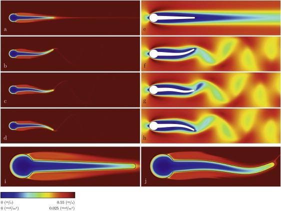
Spatial distributions of soluble substrate concentration and the liquid velocity magnitude: (a) concentration and (e) velocity for immobile streamer; (b–d) concentration and (f–h) velocity in transient conditions, when the streamer tip is moving downwards for half of an oscillation period (0.8137, 0.8149, and 0.8159 s, respectively); (i and j) magnified substrate concentration fields for static and moving streamer, respectively, showing the formation of concentration boundary layer. A high-definition animation of the streamer deformation and movement, together with the concentration and velocity magnitude fields calculated between 0.81 and 0.86 s is presented in Section S4 in the Supporting Material.
The steady-state solution was also chosen as initial condition for the time-dependent simulations with unsteady flow and oscillating structure. In the time-dependent (transient) simulation, the streamer started to vibrate after ∼0.08 s. This can be seen in the recorded y position of the streamer tip (Fig. 3 c). The velocity field reveals the formation of a Von Karman alley of vortices (Fig. 2, e–h). Corresponding to these vortices, a dynamic wake of lower solute concentration spreads behind the streamer in a wavelike shape (Fig. 2, b–d, and Fig. 2 j). As a consequence of the increasingly stronger streamer oscillation, the mass transfer also gradually increases until an oscillatory quasi-steady state is reached after ∼1 s (Fig. 3 a). Typically, the relaxation time of mass transfer toward reaching a stable state in moving conditions is longer (∼1 s, Fig. 3, a and b) than that for reaching stable streamer oscillations (∼0.1 s, Fig. 3 c). The enhancement in mass transfer is quantified by the evolution of the overall Sherwood number in time, shown in Fig. 3 a. The streamer vibration makes the steady-state mass transfer rate have an oscillatory behavior as well.
Figure 3.
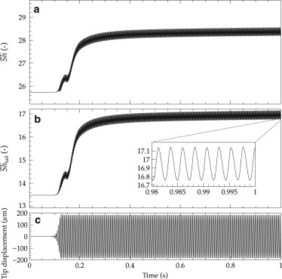
Increase of overall mass transfer when the streamer tail begins to vibrate. (a) Overall Sherwood number, , increasing from an immobile steady state (t = 0) to the oscillatory quasi-steady state (t ≈ 1 s). (b) Evolution of the evaluated only over the streamer tail, from the immobile to oscillatory steady-state. (c) Displacement of the streamer tip in time. Simulation conditions: EB = 4000 Pa, u0 = 0.4 m/s.
The overall mass transfer is enhanced during oscillations compared with the immobile structure case. Initially, when the streamer tail is not moving, . Once vibrating, the reaches a maximum of 28.5, which is an 11% increase in the mass transfer for the whole structure due to the movement of the streamer tail. Calculated along the tail section only, the streamer movement can induce an even larger mass transport enhancement of 27% (Fig. 3 b).
A closer look at the patterns from Fig. 4 during a few oscillation periods reveals that the mass transfer at different moments in time is directly correlated to the position of the points on Γ and their transverse speed, e.g., streamer tip position and tip movement speed, as shown in Fig. 4. The maximum mass transfer enhancement (Fig. 4 c) occurs close to the moment when the tip speed is the largest (in absolute value, Fig. 4 b). Consequently, the frequency of Sherwood number oscillations is exactly two times the oscillation frequency of the tip. These observations strongly point to the main cause of mass transfer enhancement when the streamer is moving: the increased relative velocity between liquid and the biofilm structure. In fact, this conclusion is not surprising because a faster fluid velocity (i.e., a higher Reynolds number Re) is normally correlated to thinner boundary layers and increased mass transfer coefficients (i.e., higher Sh numbers).
Figure 4.
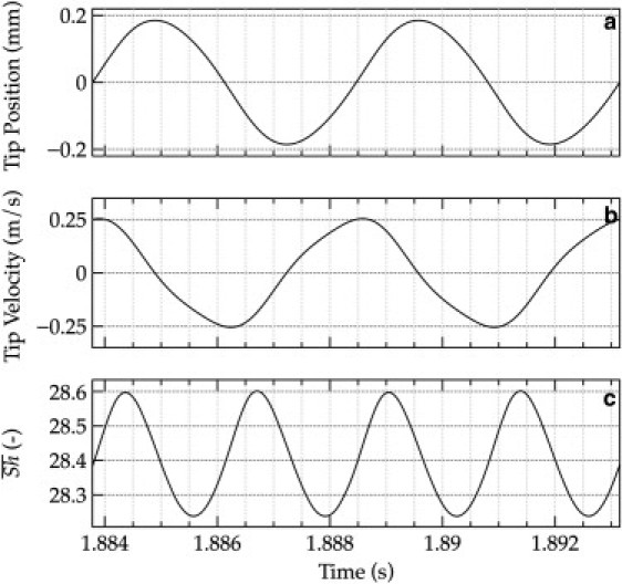
Detailed representation of the streamer oscillation characteristics over a short period of time. (a) Streamer tip displacement; (b) streamer tip velocity; and (c) overall Sherwood number, , during two oscillation periods. The mass transfer number reaches a maximum close to the middle point between the extreme positions of the tip—when also the speed of the tip is at maximum. Simulation conditions: EB = 4000 Pa, u0 = 0.4 m/s.
Although it can be expected that the streamer tip will benefit from the movement, the question is also how much the mass transfer is enhanced at other positions on the streamer surface. Fig. 5 shows the local profiles of the concentration, with Sherwood number for the whole streamer body and a detailed Sh distribution along the tail section, in static and moving conditions. The maximum local mass transfer (Sh = 110) occurs at the streamer base, which is exposed frontally to the flow (sections I–II and VIII–I on Fig. 5 a); however, this value cannot be improved by the tail movement. The mass transfer quickly falls toward a minimum at the fluid boundary layer separation zone (point II on Fig. 5, visible also in Fig. 2, i and j), where the fluid flow becomes detached from the surface of the streamer head. The mass transfer then starts to increase toward the tip (point V), where along the tail it reaches a relatively stable value of Sh between 13–14 and 17–18 for the static and moving cases, respectively. Fig. 5 c shows the relative enhancement of Sh compared to the static case along the streamer perimeter, which demonstrates that the regions close to the tip of moving structure can reach very significant mass transfer increase of 50–135%. The concentration profile on the biofilm surface (Fig. 5 d), the associated concentration maxima points (Fig. 5 e), and the relative increase in concentration (Fig. 5 f) also exhibit similar trends, with maxima locations even closer to the streamer tip (point V). Hence, it can be concluded that the main contribution to the overall mass transfer enhancement comes from the regions on the streamer tail closer to the tip, along the points IV, V, and VI. Moreover, the strongly increased mass transfer near the streamer tip can have, as an effect, a greater microbial growth rate in that region. This enhanced growth could lead to a faster elongation of the streamer tail and may constitute one of the causes why streamers actually exist.
Figure 5.
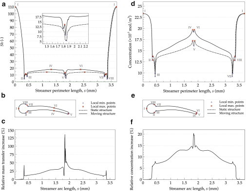
Distributions of local mass transfer (represented by Sh) and concentrations over the whole biofilm-liquid boundary and their relative increase in oscillatory conditions in respect to the static case. Values for the static case (dashed lines) are compared along the biofilm outer perimeter, s, with those obtained in moving conditions: (a and d) Local Sherwood number, Sh, and concentration; (b and e) places on the biofilm-liquid boundary where the local Sh maxima and minima occurred and the corresponding locations for concentration extremes; (c) relative increase in the local mass transfer; (f) relative increase in the concentration at the biofilm surface.
The mass transfer increase is also visible from the reduced thickness of the boundary layer near the tail tip in oscillatory conditions (compare i and j of Fig. 2). Fig. 2 j shows a tip that is far better supplied with substrate than it is for the static case. This is further underlined in Fig. 6, where the boundary layer thickness can be seen clearly for the concentration profiles constructed at the point IV in the direction normal to the biofilm surface. Although starting from the same c0 value in bulk liquid, the concentrations for the moving structure are higher in the boundary layer compared with a static streamer. Consequently, the concentration inside the biofilm also remains higher for the moving streamer and could lead to more microbial growth.
Figure 6.
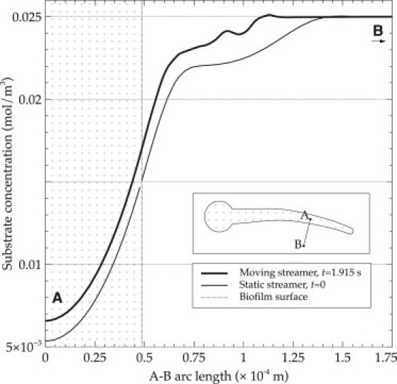
Increase of substrate concentration in the biofilm in moving conditions. Concentration profiles are computed along the line segment A–B, perpendicular to the biofilm surface, as shown in the streamer (inset). The tail is moving downward.
Mass transfer enhancement as a function of flow velocity and biofilm flexibility
The effect of flow velocity on mass transfer in oscillating streamers was studied by setting various inlet flow velocities u0 ranging from 0.1 to 0.45 m/s while keeping other model parameters unchanged. These conditions correspond to Reynolds numbers (Re, relative to the streamer head diameter d) between 33 and 150. It is well known that at faster flows the mass transfer is higher due to the thinner concentration boundary layer formed around the structure. For simplified configurations, e.g., forced convection past a cylinder in laminar flow regime, Sh can be approximated as Sh = f(Re0.5, Sc0.33), where Sc is the Schmidt number (19). For the more complex geometrical structure analyzed in this study, the increase in mass transfer with increased Re in static cases deviates from this dependency. Fig. 7 shows the effect of different flow velocities and movement on mass transfer, with and without the streamer motion. As expected, the Sherwood number of static streamers, i.e., steady-state simulations without movement, increases by increasing the flow velocity, and scales with Re0.42. However, the oscillating streamers exhibit a different behavior. The higher the velocity the higher the mass transfer increase compared to a static streamer, a 15–20% increase for the whole structure. For EB = 4000 Pa, for example, Sh scales with Re0.63 and for the more flexible structure having EB = 1000 Pa with Re0.74 in the interval from Re = 80–150. The mass transfer enhancement is even more pronounced for the tail section (Fig. 3 b).
Figure 7.
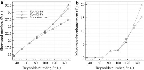
Increase of overall mass transport for faster flows, and for the oscillating streamers with different elasticities. (a) Effect of fluid velocity, represented by Re, on mass transfer, represented by time-averaged overall Sherwood number, ; (b) mass transfer enhancement of oscillating biofilm streamers with different flexibilities relative to the static structure. The more flexible structure with Young's modulus of EB = 1000 Pa permits more substrate transfer than the stiffer one with EB = 4000 Pa.
Several measurements of mechanical properties of biofilms have produced various results for the elastic modulus EB (see Lau et al. (20), and see Table S2 in the Supporting Material, for a summary). As a result, it has been proposed (21,22) that this variety in the biofilm elasticity might be an adaptive response to different shear environments (e.g., through the modification of extracellular polymeric substances) and that biofilms may benefit from having viscoelastic properties. Hence, the question that arises is whether the alteration of the mechanical properties of the biofilm (here the elasticity) also has a profound effect on the substrate uptake of the biofilm. We therefore investigated numerically two flexible biofilm streamers with different elasticities of EB = 1000 Pa and EB = 4000 Pa, values that lay in the range of reported biofilm elasticity in the literature (23–25). There are also lower reported values, but these could not be investigated with this model because the numerical method used fails at very high flexibility. For higher values of the elasticity modulus EB the biofilm is too stiff to begin oscillating and there will be no movement.
Fig. 7, a and b, shows that at lower flow velocities the contribution of a higher biofilm flexibility to mass transfer is minimal. For velocities higher than 0.4 m/s (Re = 133), however, the mass transfer enhancement becomes relatively higher for more flexible structures (EB = 1000 Pa). Hence, from the substrate uptake point of view, a more flexible (more elastic) streamer structure is favorable. On the other hand, from the drag point of view, a more flexible structure in the flow also experiences a higher drag and stress on the body (26), and hence it would develop a higher chance of breakage and detachment. This latter balancing between favorable substrate uptake and unfavorable drag should put a theoretical constraint on how flexible a biofilm can become.
The interplay of fluid flow, drag, substrate transport, and biofilm growth
In a previous study (8) we showed that, due to the streamlined form, the drag on a streamer with L/d ≈ 5 at u0 = 0.4 m/s (Re = 133) can be 14% lower than on a biofilm with a circular base having the same projected area to the flow. If we consider a static streamer, this relative drag reduction by the streamlined shape considered is even higher (39%). Despite constituting a drawback in respect to the fluid forces that the biofilm experiences, these oscillations also increase the substrate uptake to the biofilm for as high as 20% on the whole structure (Fig. 7) and even significantly higher at the tail area closer to the tip. It should also be noted that a static and rigid biofilm is also more vulnerable to changes of local flow directions, very common in the rivers, whereas a flexible streamer aligns better and moves with the flow.
Overall, the development of the streamer's teardrop shape might be a result of the viscoelastic nature of the biofilm matrix exposed to fluid forces. The initial patchy biofilm structure elongates being pulled by the flow and could follow a simultaneous transient self-similar bending (27,28), where the newly produced microbial cells are also pushed downstream (9). Nevertheless, this study shows that the flexible elongated biofilm shape may create an opportunity for bacteria to benefit from the higher substrate availability that the oscillations provide and therefore form highly competitive niches in nature (29). Higher substrate availability toward the tip also facilitates higher growth at the tail section while being shielded from fluid forces in the wake of the head section (blue area in Fig. 2, e–h). Especially under high shear and substrate limitation the streamer will mainly grow at the tip and thereby self-sustain the streamer formation. Eventually, there must be a trade-off between faster growth rate due to more substrate and detachment induced by the larger forces present when the biofilm streamers oscillate.
The results presented here demonstrate that the main contribution to the increase of mass transfer comes from the flow-induced movement of the biofilm tail, despite the fact that the tail resides in the diffusion-dominated wake of the head section (Fig. 2). Accordingly, using a broader view, we propose that the relative movement of any extension of biofilms, e.g., due to filamentous strains or heterogeneous surface structures that vibrate due to local flow instabilities, should contribute to the increase of substrate uptake.
Conclusion
In this work we studied numerically the relation among substrate transport, and flexibility and reconfiguration of oscillating biofilm streamers in substrate-limited conditions at various flow velocities. A fluid-structure interaction model was coupled with the mass transport of a reactive solute consumed by the microbial cells within the biofilm. The calculated mass transfer parameters showed that the movement of these biofilm structures can increase the substrate uptake substantially. The main contribution to the overall increase of substrate (or another solute) transfer in a biofilm streamer comes from the flow-induced movement of the streamer tail. Concentration profiles and solute fluxes evaluated along the biofilm surface show that regions near the streamer tip can benefit from a mass transfer as high as double when the streamer is oscillating, compared with the static conditions. An analysis of oscillation periods of the tip position and of the mass transfer coefficient reveals that the reason of transfer enhancement is the increase in speed of tip movement relative to the surrounding liquid. Faster liquid velocity and higher biofilm flexibility begin to increase considerably the substrate mass transfer by more intense streamer tail vibrations only above a minimum flow velocity. Although we prove here that streamer oscillations enhance mass transfer in biofilms, there are a number of simplifications (e.g., the two- versus the three-dimensional, the uniformity of biomass distribution and of its mechanical properties) that could make the model results quantitatively deviate from experimental measurements. The results and methodology from this work can also be applied to other fields of research, e.g., encouraging the development of novel micromixing modules in microfluidic systems and flexible artificial biofilm supports that benefit from the enhanced mass transfer while having lower susceptibility to breakage of the flexible tails.
Acknowledgments
This study was funded by the Oswald Schulze Stiftung (grant AZ 1497/07 (5144)). The work of C. Picioreanu was financially supported by the Netherlands Organization for Scientific Research (NWO VIDI grant 864-06-003).
Footnotes
Danial Taherzadeh's present addess is Oncolead GmbH & Co. KG, Planegg, Germany.
Supporting Material
References
- 1.Vogel S. Princeton University Press; Princeton, NJ: 2003. Comparative Biomechanics: Life's Physical World. [Google Scholar]
- 2.Stoodley P., Lewandowski Z., Lappin-Scott H.M. Oscillation characteristics of biofilm streamers in turbulent flowing water as related to drag and pressure drop. Biotechnol. Bioeng. 1998;57:536–544. doi: 10.1002/(sici)1097-0290(19980305)57:5<536::aid-bit5>3.0.co;2-h. [DOI] [PubMed] [Google Scholar]
- 3.Edwards K.J., Bond P.L., Banfield J.F. An archaeal iron-oxidizing extreme acidophile important in acid mine drainage. Science. 2000;287:1796–1799. doi: 10.1126/science.287.5459.1796. [DOI] [PubMed] [Google Scholar]
- 4.Besemer K., Singer G., Battin T.J. Biophysical controls on community succession in stream biofilms. Appl. Environ. Microbiol. 2007;73:4966–4974. doi: 10.1128/AEM.00588-07. [DOI] [PMC free article] [PubMed] [Google Scholar]
- 5.Vrouwenvelder J., Picioreanu C., van Loosdrecht M. Biofouling in spiral wound membrane systems: three-dimensional CFD model based evaluation of experimental data. J. Membr. Sci. 2010;346:71–85. [Google Scholar]
- 6.Rusconi R., Lecuyer S., Stone H.A. Laminar flow around corners triggers the formation of biofilm streamers. J. R. Soc. Interface. 2010;7:1293–1299. doi: 10.1098/rsif.2010.0096. [DOI] [PMC free article] [PubMed] [Google Scholar]
- 7.Rusconi R., Lecuyer S., Stone H.A. Secondary flow as a mechanism for the formation of biofilm streamers. Biophys. J. 2011;100:1392–1399. doi: 10.1016/j.bpj.2011.01.065. [DOI] [PMC free article] [PubMed] [Google Scholar]
- 8.Taherzadeh D., Picioreanu C., Horn H. Computational study of the drag and oscillatory movement of biofilm streamers in fast flows. Biotechnol. Bioeng. 2010;105:600–610. doi: 10.1002/bit.22551. [DOI] [PubMed] [Google Scholar]
- 9.Stoodley P., Dodds I., Lappin-Scott H.M. Influence of hydrodynamics and nutrients on biofilm structure. J. Appl. Microbiol. 1998;85(Suppl 1):19S–28S. doi: 10.1111/j.1365-2672.1998.tb05279.x. [DOI] [PubMed] [Google Scholar]
- 10.Siegrist H., Gujer W. Mass transfer mechanisms in a heterotrophic biofilm. Water Res. 1985;19:1369–1378. [Google Scholar]
- 11.Zhang, T. C., P. L. Bishop, and J. T. Gibbs. 1994. Effect of roughness and thickness of biofilms on external mass transfer resistance [conference proceedings paper]. In Critical Issues in Water and Wastewater Treatment. Am. Soc. Chem. Eng. 593–600.
- 12.Nagaoka H., Sanda K. Simulation of turbulence and dissolved oxygen concentration profiles over biofilm using k turbulence models. Water Sci. Technol. 2005;36:147–156. [Google Scholar]
- 13.Wäsche S., Horn H., Hempel D.C. Influence of growth conditions on biofilm development and mass transfer at the bulk/biofilm interface. Water Res. 2002;36:4775–4784. doi: 10.1016/s0043-1354(02)00215-4. [DOI] [PubMed] [Google Scholar]
- 14.Picioreanu C., van Loosdrecht M.C.M., Heijnen J.J. A theoretical study on the effect of surface roughness on mass transport and transformation in biofilms. Biotechnol. Bioeng. 2000;68:355–369. doi: 10.1002/(sici)1097-0290(20000520)68:4<355::aid-bit1>3.0.co;2-a. [DOI] [PubMed] [Google Scholar]
- 15.Eberl H.J., Picioreanu C., van Loosdrecht M.C.M. A three-dimensional numerical study on the correlation of spatial structure, hydrodynamic conditions, and mass transfer and conversion in biofilms. Chem. Eng. Sci. 2000;55:6209–6222. [Google Scholar]
- 16.Picioreanu C., Van Loosdrecht M.C., Heijnen J.J. Effect of diffusive and convective substrate transport on biofilm structure formation: a two-dimensional modeling study. Biotechnol. Bioeng. 2000;69:504–515. doi: 10.1002/1097-0290(20000905)69:5<504::aid-bit5>3.0.co;2-s. [DOI] [PubMed] [Google Scholar]
- 17.Shaw T., Winston M., Stoodley P. Commonality of elastic relaxation times in biofilms. Phys. Rev. Lett. 2004;93:098102. doi: 10.1103/PhysRevLett.93.098102. [DOI] [PubMed] [Google Scholar]
- 18.Deen W.M. Oxford University Press; New York: 1998. Analysis of Transport Phenomena. [Google Scholar]
- 19.Khan W.A., Culham J.R., Yovanovich M.M. Fluid flow around and heat transfer from an infinite circular cylinder. J. Heat Transfer. 2005;127:785–790. [Google Scholar]
- 20.Lau P.C., Dutcher J.R., Lam J.S. Absolute quantitation of bacterial biofilm adhesion and viscoelasticity by microbead force spectroscopy. Biophys. J. 2009;96:2935–2948. doi: 10.1016/j.bpj.2008.12.3943. [DOI] [PMC free article] [PubMed] [Google Scholar]
- 21.Hall-Stoodley L., Costerton J.W., Stoodley P. Bacterial biofilms: from the natural environment to infectious diseases. Nat. Rev. Microbiol. 2004;2:95–108. doi: 10.1038/nrmicro821. [DOI] [PubMed] [Google Scholar]
- 22.Salta M., Wharton J.A., Stokes K.R. Designing biomimetic antifouling surfaces. Philos. Transact. A Math. Phys. Eng. Sci. 2010;368:4729–4754. doi: 10.1098/rsta.2010.0195. [DOI] [PubMed] [Google Scholar]
- 23.Stoodley P., Lewandowski Z., Lappin-Scott H.M. Structural deformation of bacterial biofilms caused by short-term fluctuations in fluid shear: an in situ investigation of biofilm rheology. Biotechnol. Bioeng. 1999;65:83–92. [PubMed] [Google Scholar]
- 24.Körstgens V., Flemming H.C., Borchard W. Uniaxial compression measurement device for investigation of the mechanical stability of biofilms. J. Microbiol. Methods. 2001;46:9–17. doi: 10.1016/s0167-7012(01)00248-2. [DOI] [PubMed] [Google Scholar]
- 25.Aravas N., Laspidou C.S. On the calculation of the elastic modulus of a biofilm streamer. Biotechnol. Bioeng. 2008;101:196–200. doi: 10.1002/bit.21865. [DOI] [PubMed] [Google Scholar]
- 26.Zhu L., He G., Fang S. An immersed boundary method based on the lattice Boltzmann approach in three dimensions, with application. Comput. Math. Appl. 2011;61:3506–3518. [Google Scholar]
- 27.Alben S., Shelley M., Zhang J. Drag reduction through self-similar bending of a flexible body. Nature. 2002;420:479–481. doi: 10.1038/nature01232. [DOI] [PubMed] [Google Scholar]
- 28.Alben S., Shelley M., Zhang J. How flexibility induces streamlining in a two-dimensional flow. Phys. Fluids. 2004;16:1694–1713. [Google Scholar]
- 29.Besemer K., Hödl I., Battin T.J. Architectural differentiation reflects bacterial community structure in stream biofilms. ISME J. 2009;3:1318–1324. doi: 10.1038/ismej.2009.73. [DOI] [PubMed] [Google Scholar]
- 30.Henze M. IWA Publishing; London, UK: 2000. Activated Sludge Models ASM1, ASM2, ASM2d, and ASM3. [Google Scholar]
Associated Data
This section collects any data citations, data availability statements, or supplementary materials included in this article.